


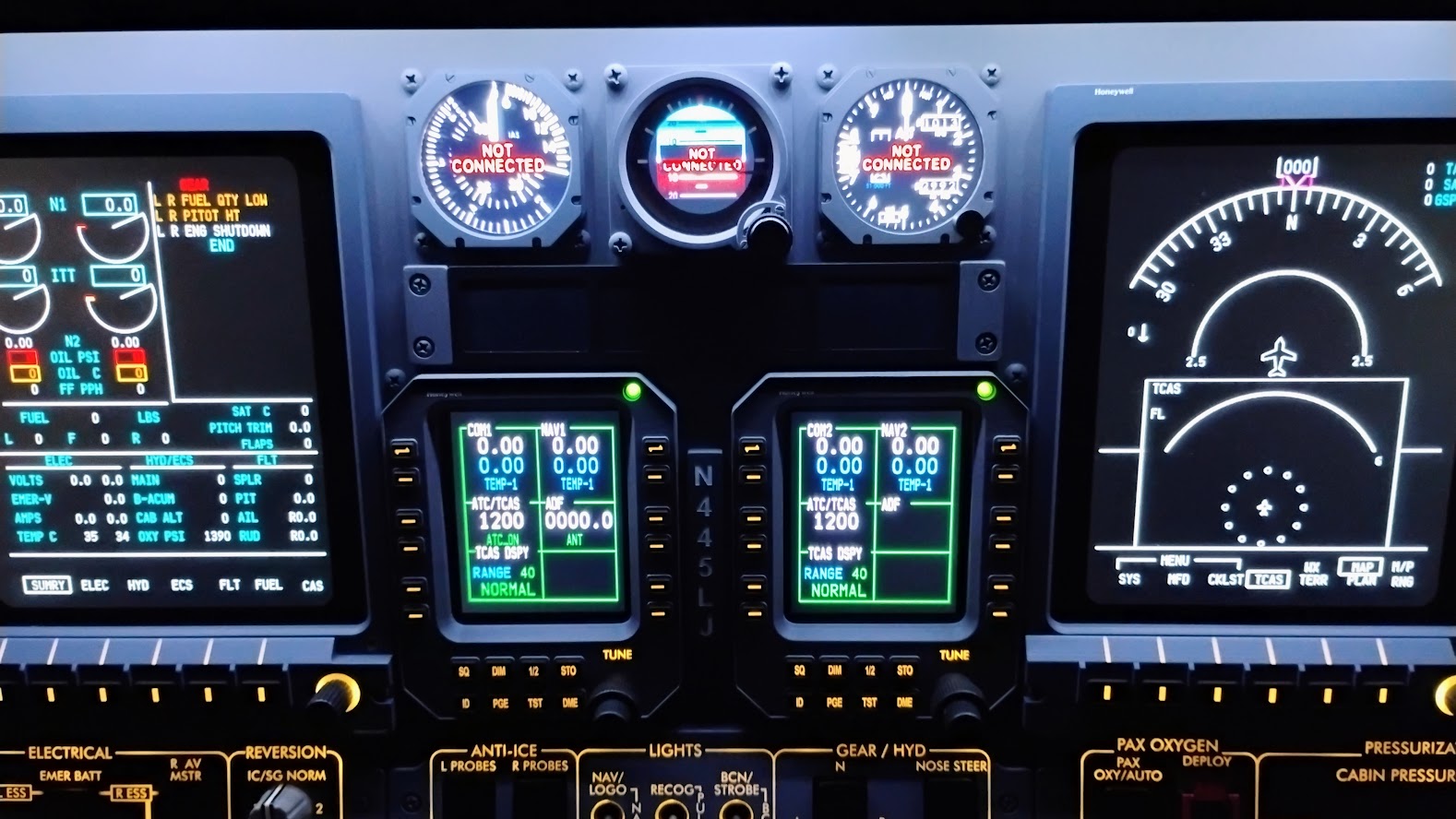
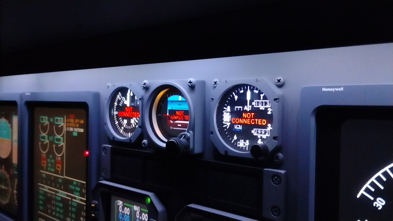
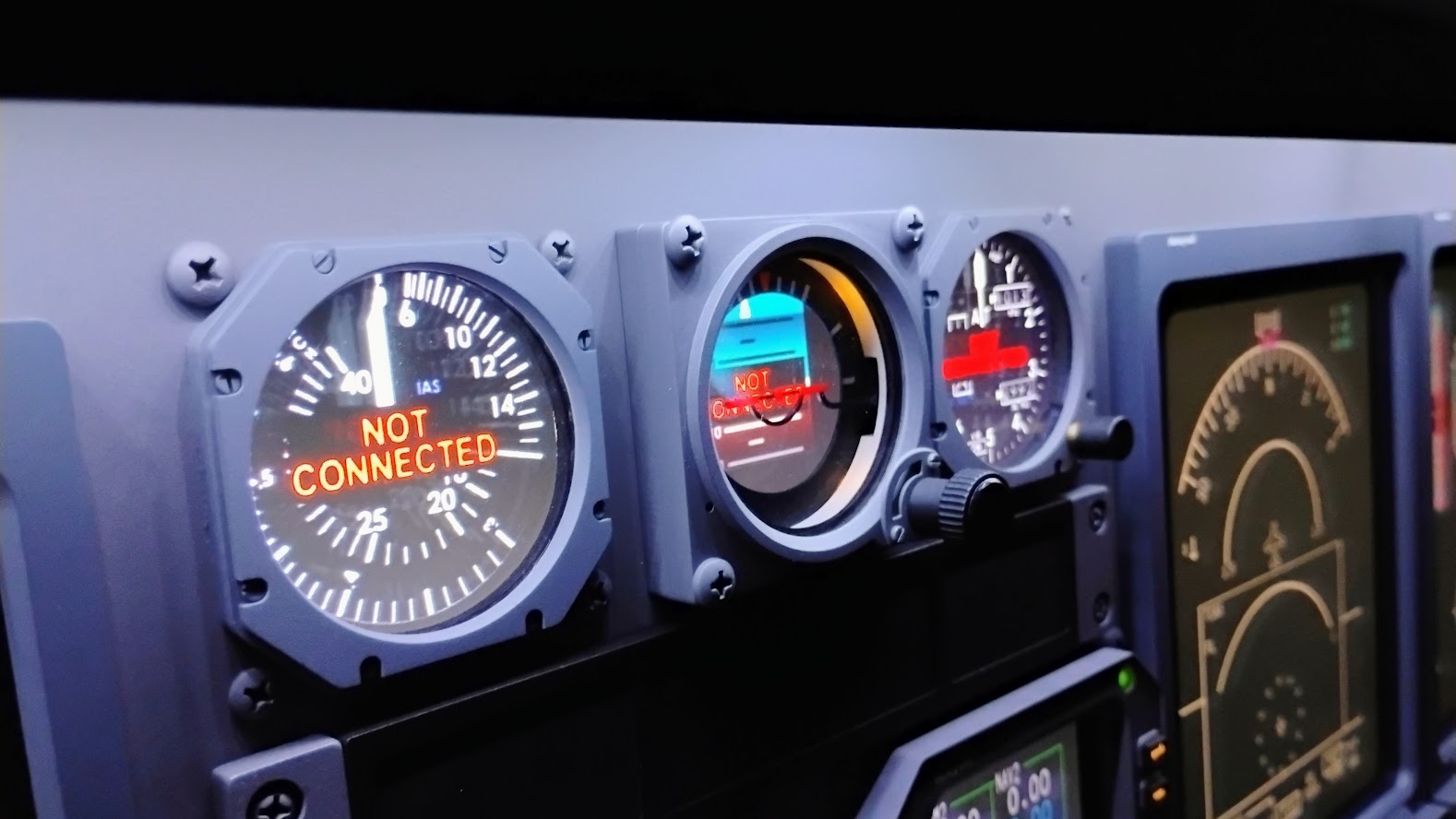
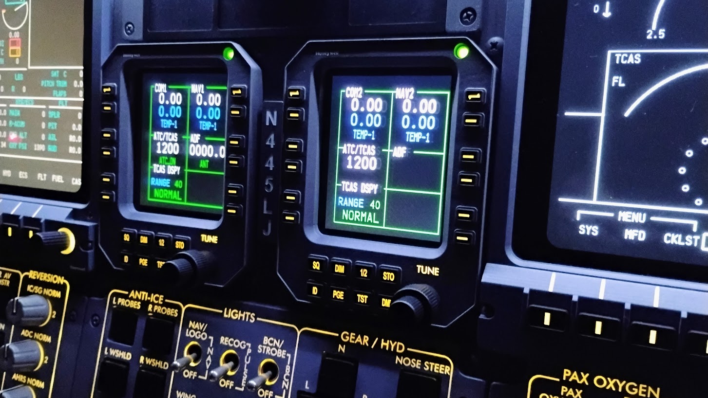
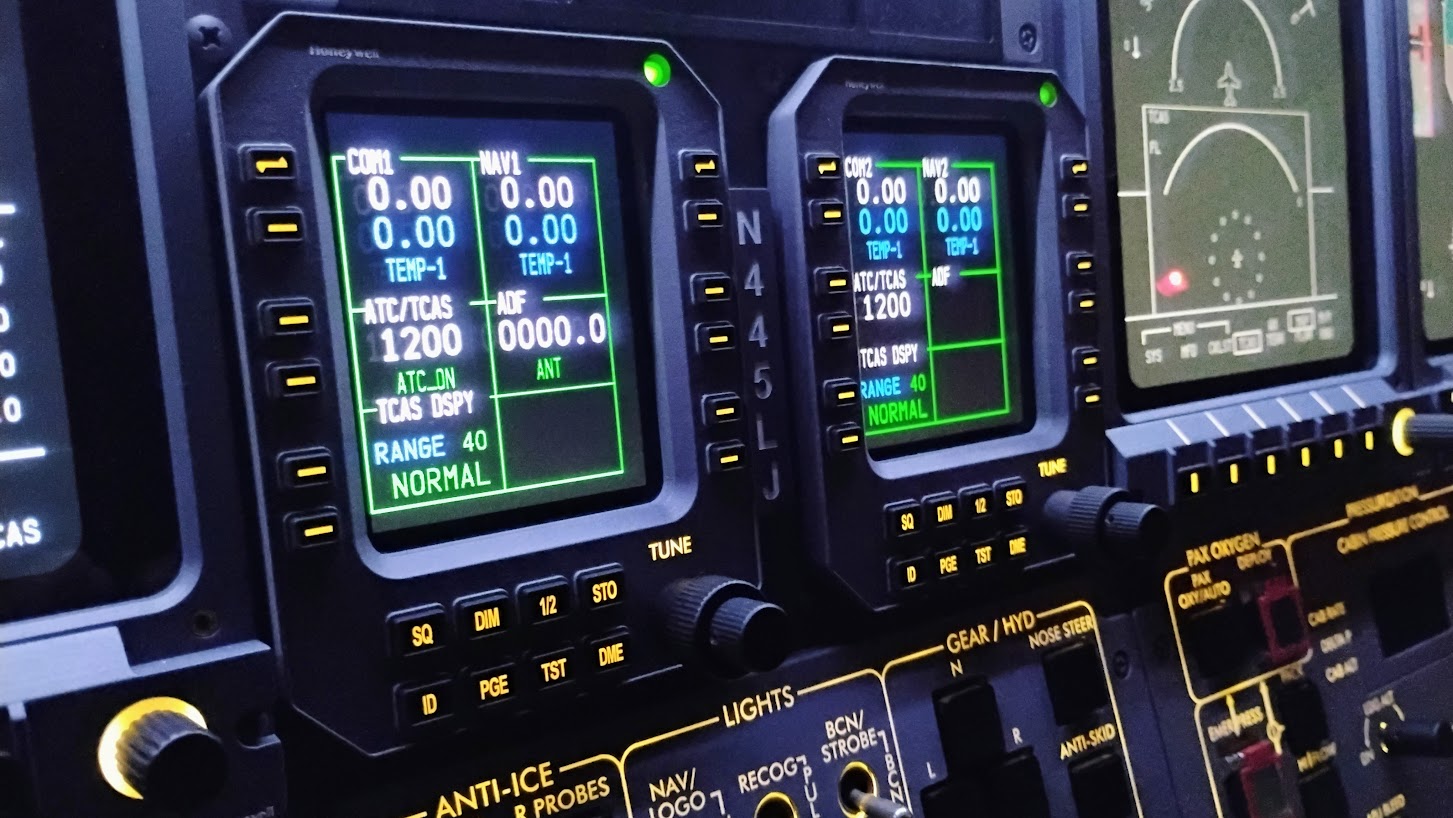
Hey guys, I got the center monitor solution all sorted out however, I am not 100% happy with the cheap monitors I currently have. They "should" be able to be viewed from either the left or right side being that they are now oriented in landscape mode. But as it is, they only look good when viewed from straight on or from the left side. The right side is as bad if not worse than what we had prior. These cheap monitors can be found for as little as $17 each and fit in the spaces perfectly but finding a pair that does not have damaged pixels or the screens completely grayed out when they should be blacked out is nearly impossible. Out of five LCD screens ordered, I have one that is of good quality but still looks terrible when viewed from the right side. I have another LCD screen but it's barely usable with a couple bad pixels although they are hidden between the standby gauges where they can not be seen. I know someone makes quality 9 inch LCD screens, even if they cost a little more or even a lot more, it would be worth having them in our projects. So the question is, has anyone been able to source quality 9 inch LCD screens? Today I was fishing with my grandson Jett and he was using a neat little gizmo that could spy in the fish. It's a battery operated 4.3" LCD screen attached to a 50 foot cable with a tiny camera at the other end. What I found interesting about this screen was that it could be viewed from the extreme left or right without the issues we are seeing with these cheap 9 inch LCD screens. The pictures are not great but good enough that you can see the angle the photos are taken from don't effect the quality of the image. (If you are wondering if we caught any fish, it was too cold!) The point of this is if someone can get the viewing angle solved on a 4.3" LCD screen we should be able to find a quality 9" LCD screen. I know it's out there and once we can identify it, I plan on replacing the two I currently have with the new ones. In the meantime, here is what I have to date and will be good enough for testing in the near future. I came up with a couple tricks that can be applied to these LCD screens or our future high quality LCD screens. Because of the low profile fasteners on the back side of the MIP for the RMUs, HSI standby gauge and the altimeter encoder, there has to be about a .125" gap between the back side of the MIP and the face of the LCD screens. I used .25" wide and .125" thick black foam single side tape to "ring around" the Airspeed gauge and the Altimeter gauge to block unwanted LCD screen light. Here is a closer look at the Airspeed gauge. And here is the Altimeter standby gauge. This foam ring blocks all unwanted light bleed from the LCD screen so that only the LCD gauge can be seen and nothing more. The HSI standby gauge in the middle does not need this foam ring. The other thing that I had to do was trim the aluminum glareshield a little to make room for the LCD screen. I ended up putting some double side foam tape behind the LCD screens to push them closer to the back side of the MIP a little closer. Here I have the MIP in place. I even notched out a couple places for the altimeter encoder wires and the HSI back lighting wires. I do like that only about a half inch of the top 9" LCD screen protrudes up above the aluminum glareshield. I used black craft tape to mask this small area to keep any unwanted light bleed from seeping out and into other areas. Last but not least, here is a look at how I mounted the control boards for the LCD screens. I also went ahead and mounted the remote control buttons in a place that I could potentially reach from the avionics bay if needed. So it all fits and mounts perfectly, that's the good news! The bad news is I am on the hunt to replace these crappy 9" LCD screens and will have to figure it all out again. Hopefully some of the work I have already done will not be wasted effort. If anyone has a source to some high quality 9 inch LCD screens, please share! Hey guys, I got the center monitor solution all sorted out however, I am not 100% happy with the cheap monitors I currently have. They "should" be able to be viewed from either the left or right side being that they are now oriented in landscape mode. But as it is, they only look good when viewed from straight on or from the left side. The right side is as bad if not worse than what we had prior. These cheap monitors can be found for as little as $17 each and fit in the spaces perfectly but finding a pair that does not have damaged pixels or the screens completely grayed out when they should be blacked out is nearly impossible. Out of five LCD screens ordered, I have one that is of good quality but still looks terrible when viewed from the right side. I have another LCD screen but it's barely usable with a couple bad pixels although they are hidden between the standby gauges where they can not be seen. I know someone makes quality 9 inch LCD screens, even if they cost a little more or even a lot more, it would be worth having them in our projects. So the question is, has anyone been able to source quality 9 inch LCD screens? Today I was fishing with my grandson Jett and he was using a neat little gizmo that could spy in the fish. It's a battery operated 4.3" LCD screen attached to a 50 foot cable with a tiny camera at the other end. What I found interesting about this screen was that it could be viewed from the extreme left or right without the issues we are seeing with these cheap 9 inch LCD screens. The pictures are not great but good enough that you can see the angle the photos are taken from don't effect the quality of the image. (If you are wondering if we caught any fish, it was too cold!) The point of this is if someone can get the viewing angle solved on a 4.3" LCD screen we should be able to find a quality 9" LCD screen. I know it's out there and once we can identify it, I plan on replacing the two I currently have with the new ones. In the meantime, here is what I have to date and will be good enough for testing in the near future. I came up with a couple tricks that can be applied to these LCD screens or our future high quality LCD screens. Because of the low profile fasteners on the back side of the MIP for the RMUs, HSI standby gauge and the altimeter encoder, there has to be about a .125" gap between the back side of the MIP and the face of the LCD screens. I used .25" wide and .125" thick black foam single side tape to "ring around" the Airspeed gauge and the Altimeter gauge to block unwanted LCD screen light. Here is a closer look at the Airspeed gauge. And here is the Altimeter standby gauge. This foam ring blocks all unwanted light bleed from the LCD screen so that only the LCD gauge can be seen and nothing more. The HSI standby gauge in the middle does not need this foam ring. The other thing that I had to do was trim the aluminum glareshield a little to make room for the LCD screen. I ended up putting some double side foam tape behind the LCD screens to push them closer to the back side of the MIP a little closer. Here I have the MIP in place. I even notched out a couple places for the altimeter encoder wires and the HSI back lighting wires. I do like that only about a half inch of the top 9" LCD screen protrudes up above the aluminum glareshield. I used black craft tape to mask this small area to keep any unwanted light bleed from seeping out and into other areas. Last but not least, here is a look at how I mounted the control boards for the LCD screens. I also went ahead and mounted the remote control buttons in a place that I could potentially reach from the avionics bay if needed. So it all fits and mounts perfectly, that's the good news! The bad news is I am on the hunt to replace these crappy 9" LCD screens and will have to figure it all out again. Hopefully some of the work I have already done will not be wasted effort. If anyone has a source to some high quality 9 inch LCD screens, please share! Hey guys, I finally have an acceptable and satisfactory solution to the center LCD screen issue. First, let me share with you what I was getting with the previous 9 inch LCD screens. They were impossible to see anything when viewed from the right side, even 15 or 20 degrees to the right yielded horrible results. Standby LCD screen. On top of that, one of them was missing the RED part of the RGB (Red, Green, Blue) RMU LCD screen. They don't look too bad when viewed straight on but the quality was still poor. For me, the only option was to ditch these cheap LCDs and go out on the hunt for a better option. Thankfully I found it. This 9 inch LCD screen is twice as expensive but it works and can be viewed from any angle within the cockpit. Still not bad at just $63. Here are a couple photos of what this new LCD screen looks like. This is right out of the box without any adjustments made yet. And it actually looks better in person with the naked eye. The "black" background looks blacker than what it appears in the photos. Compare these two photos to the previous LCD screens. It's a night and day difference. One thing that I noticed right off the bat was the physical thickness of the new LCD screen. It's .19" thick compared to .11" of the older LCD screens. (The one on the left is the newer and better screen) The good news is the left to right and up to down dimensions were nearly identical to the older crappy LCD screens so although there was some modifications needed from the previous try to this one, everything was within reason. One other thing I want to cover real quick. With the previous LCD screens, they only required 5 volt power via a USB connection. The plan there was to just plug it into a USB socket on the computer to supply power. Now with these new LCD screens, they require 12 volt power and they came with a 12 volt power adapter. You could just use the 12 volt power adapter so long as you also used a 90 degree power plug adapter. However, our plan is to use our existing 12 volt power supply system. I will be using the Right EMER/HOT BUS for both the Standby and the RMU 9 inch LCD screens. This way as soon as the Right power supply is switched ON, power will be applied to the two LCD screens and will remain powered during the duration of the flight no matter what powered emergencies arise. I tested the LCD screen hooked into the Right HOT BUS and also ran the pedal adjust actuators to see if there was any reason why this would not work. Everything was as smooth as butter. While I am thinking about it, a couple additional things you will need to purchase will be 90 degree adapters for the power supply lines, the HDMI connections and the VGA connections because of how tight it is in the center MIP backer area. HDMI and VGA? You only need one! But during my testing with my current computers, I tried to use the HDMI connection back to the computer and it works fine.....until you turned the computer off. The 9 inch monitor would not get recognized at start up and the standby gauges would revert back to the main LCD screen requiring manual setup....again. Then I tried using the VGA connection. By the way, they use a USB MINI B which also double as a VGA mini on the LCD PCB board. You just have to use a 90 degree adapter. What I found is that the VGA connection looks fine, is stable and I am able to turn the computer off and the power to the power supply. Then I am able to bring things back up in either order and the standby gauges remain on the 9 inch LCD screen as you would expect. This might be because I am testing with dated Windows 7 machines. The plan is to install both the VGA and HDMI 90 degree adapters so that I have the option for either with the new future computers. TUTORIAL CONTINUATION Now that I think we have finally found a viable option to the 9 inch LCD screens, we need to do a little modification to make them fit. The previous solution called for a solid 9 inch screen backer for the top Standby Gauges. This is what we were planning for previously. The solution to making these new LCD screens fit was to create an open backer similar to the lower one. The LCD PCB will be mounted to the back side of the LCD screen and sit in this shallow pocket. This space is very tight and requires every available mm to make this work, therefor, the pins on the back side have to be snipped short and filed down. This photo shows how long some of the pins are. And this photo shows them after I snipped them short. I used a fingernail file to remove the burs and some blue painters tape to protect the PCB from the file. Once the pins were snipped and filed, I hit them all with a soldering iron to reset the solder joints. This was just enough to do the trick and gain the space needed to make it all fit. However, the PCB will be sitting right on the backside of the metal screen case. The next problem to overcome was to prevent shorting. Here I used a thin piece of stencil plastic as an insulator. This is held in place with Scotch tape on all four sides. It does not take a lot of double sided sticky foam tape to hold the PCB to the white plastic stencil sheet. As a matter of fact, less is better because if you ever have to remove the PCB, it will be manageable with just the squares of tape in the four corners. Additionally, I am using 3M double sided thin tape for the corners of the LCD screen to hold the LCD screen to LCD backer. (I am still waiting for the VGA 90 degree adapters to arrive) Here is what it looks like from the rear. Everything fits great! The only other thing I need to check for is heat generated from the components on the PCB. There is about 3mm of space between the PCB and the back side of the LCD screen. I don't think there will be an issue but I still need to check to make sure we are good. This is what the update kit looks like to fix the previous best bad idea! Not much to it. Reference the bevel buttons along the bottom to turn the power on and off and to make setting adjustments. I have found that once you make your settings, you can unplug the button bar and the LCD will remember it's settings and turn itself on when power is applied. So all good there. Here is a photo of the LCD bezel. The buttons are touch sensitive, meaning just barely touching a button is enough to trigger a response, therefor, I am afraid to try to remove the button PCB from the bezel. I decided to trim the majority of the plastic bezel away to make it easier if setting adjustments are needed in the future. I am also looking to see if there is a way to mount this modified button bezel in behind the MIP backer. I have already been doing some test fitting of this modified button bezel but won't be able to come up with a final plan until I have both 9 inch LCDs installed. (Waiting on some packages to arrive!) Another update as soon as the remaining parts arrive. So far so good! Hey guys, I finally have an acceptable and satisfactory solution to the center LCD screen issue. First, let me share with you what I was getting with the previous 9 inch LCD screens. They were impossible to see anything when viewed from the right side, even 15 or 20 degrees to the right yielded horrible results. Standby LCD screen. On top of that, one of them was missing the RED part of the RGB (Red, Green, Blue) RMU LCD screen. They don't look too bad when viewed straight on but the quality was still poor. For me, the only option was to ditch these cheap LCDs and go out on the hunt for a better option. Thankfully I found it. This 9 inch LCD screen is twice as expensive but it works and can be viewed from any angle within the cockpit. Still not bad at just $63. Here are a couple photos of what this new LCD screen looks like. This is right out of the box without any adjustments made yet. And it actually looks better in person with the naked eye. The "black" background looks blacker than what it appears in the photos. Compare these two photos to the previous LCD screens. It's a night and day difference. One thing that I noticed right off the bat was the physical thickness of the new LCD screen. It's .19" thick compared to .11" of the older LCD screens. (The one on the left is the newer and better screen) The good news is the left to right and up to down dimensions were nearly identical to the older crappy LCD screens so although there was some modifications needed from the previous try to this one, everything was within reason. One other thing I want to cover real quick. With the previous LCD screens, they only required 5 volt power via a USB connection. The plan there was to just plug it into a USB socket on the computer to supply power. Now with these new LCD screens, they require 12 volt power and they came with a 12 volt power adapter. You could just use the 12 volt power adapter so long as you also used a 90 degree power plug adapter. However, our plan is to use our existing 12 volt power supply system. I will be using the Right EMER/HOT BUS for both the Standby and the RMU 9 inch LCD screens. This way as soon as the Right power supply is switched ON, power will be applied to the two LCD screens and will remain powered during the duration of the flight no matter what powered emergencies arise. I tested the LCD screen hooked into the Right HOT BUS and also ran the pedal adjust actuators to see if there was any reason why this would not work. Everything was as smooth as butter. While I am thinking about it, a couple additional things you will need to purchase will be 90 degree adapters for the power supply lines, the HDMI connections and the VGA connections because of how tight it is in the center MIP backer area. HDMI and VGA? You only need one! But during my testing with my current computers, I tried to use the HDMI connection back to the computer and it works fine.....until you turned the computer off. The 9 inch monitor would not get recognized at start up and the standby gauges would revert back to the main LCD screen requiring manual setup....again. Then I tried using the VGA connection. By the way, they use a USB MINI B which also double as a VGA mini on the LCD PCB board. You just have to use a 90 degree adapter. What I found is that the VGA connection looks fine, is stable and I am able to turn the computer off and the power to the power supply. Then I am able to bring things back up in either order and the standby gauges remain on the 9 inch LCD screen as you would expect. This might be because I am testing with dated Windows 7 machines. The plan is to install both the VGA and HDMI 90 degree adapters so that I have the option for either with the new future computers. TUTORIAL CONTINUATION Now that I think we have finally found a viable option to the 9 inch LCD screens, we need to do a little modification to make them fit. The previous solution called for a solid 9 inch screen backer for the top Standby Gauges. This is what we were planning for previously. The solution to making these new LCD screens fit was to create an open backer similar to the lower one. The LCD PCB will be mounted to the back side of the LCD screen and sit in this shallow pocket. This space is very tight and requires every available mm to make this work, therefor, the pins on the back side have to be snipped short and filed down. This photo shows how long some of the pins are. And this photo shows them after I snipped them short. I used a fingernail file to remove the burs and some blue painters tape to protect the PCB from the file. Once the pins were snipped and filed, I hit them all with a soldering iron to reset the solder joints. This was just enough to do the trick and gain the space needed to make it all fit. However, the PCB will be sitting right on the backside of the metal screen case. The next problem to overcome was to prevent shorting. Here I used a thin piece of stencil plastic as an insulator. This is held in place with Scotch tape on all four sides. It does not take a lot of double sided sticky foam tape to hold the PCB to the white plastic stencil sheet. As a matter of fact, less is better because if you ever have to remove the PCB, it will be manageable with just the squares of tape in the four corners. Additionally, I am using 3M double sided thin tape for the corners of the LCD screen to hold the LCD screen to LCD backer. (I am still waiting for the VGA 90 degree adapters to arrive) Here is what it looks like from the rear. Everything fits great! The only other thing I need to check for is heat generated from the components on the PCB. There is about 3mm of space between the PCB and the back side of the LCD screen. I don't think there will be an issue but I still need to check to make sure we are good. This is what the update kit looks like to fix the previous best bad idea! Not much to it. Reference the bevel buttons along the bottom to turn the power on and off and to make setting adjustments. I have found that once you make your settings, you can unplug the button bar and the LCD will remember it's settings and turn itself on when power is applied. So all good there. Here is a photo of the LCD bezel. The buttons are touch sensitive, meaning just barely touching a button is enough to trigger a response, therefor, I am afraid to try to remove the button PCB from the bezel. I decided to trim the majority of the plastic bezel away to make it easier if setting adjustments are needed in the future. I am also looking to see if there is a way to mount this modified button bezel in behind the MIP backer. I have already been doing some test fitting of this modified button bezel but won't be able to come up with a final plan until I have both 9 inch LCDs installed. (Waiting on some packages to arrive!) Another update as soon as the remaining parts arrive. So far so good! Thanks guys! The other monitors arrived along with the remaining 90 degree connectors. After a few days, I got the second 9" LCD monitor modified in the same manor as the first one and installed. I purchased a third monitor as a spare just in case one fails. If you do pick up a couple spare monitors, check them immediately to make sure they are in good working order. I failed to do this with my last batch of 9" LCD screens and once I did get around to testing them, I discovered they were all garbage. And too late to dispute the purchase with the seller. I didn't cover taking the monitors apart in the previous post but wanted to at least touch on it. This is what the back side looks like prior to taking them apart. They are actually really well built for their size. They are like miniature TVs and even have a small speaker inside it. I have no idea how it sounds because I disconnected it as we don't need it. There are 14 small screws that need to be removed in order to pull the rear cover off, with a little prying. Speaking of prying, the main green PCB also has to be gently pried out of the rear cover. Nothing hard about this, just be careful during the process. Disconnect the ribbon cable as soon as you can because if anything is going to fail, it's going to be the ribbon cable if pulled too hard in the wrong direction. Modifying the second 9" LCD screen was pretty much exactly the same as the first. The only difference is the PCB mounts to the rear side a little lower than the upper 9" LCD screen. As you can see, as long as you are using the 90 degree connectors, there is plenty of room for everything with a little room to spare. I also took the time to label the UPPER LCD and the LOWER LCD so that if I ever have them both pulled out at the same time, I wont get them mixed up with where they belong. Here is a closer look at the rear side of the UPPER LCD. Plenty of room for the 90 degree connectors. Again, I have a 90 degree HDMI connector installed but not sure if I will use it. Currently I am using VGA connections. I wish I had a camera that takes photos of what I am actually seeing. The screens look way better in person with the naked eye compared to what my phone camera is showing. But in any case, here are some photos. The left viewing angle. Straight on viewing angle. And the right viewing angle. The difference between these monitors and anything I have tried up to this point is night and day! Last but not least, an overall photo with the four Display Units lit up and working. It's all really starting to come together! During this whole process, I have also been doing some testing to insure there were no surprises. (We don't like surprises) All systems are go so far! I can shut down the computers and bring them back up and everything remembers where everything should be. I am using the "Startup" option to bring these display modules up when the computers are started. Again, this is all being tested with Windows7 machines for now. So at this point, I am finally happy with the center display monitors. Ironically, the Upper LCD monitor is considered "temporary" because one day in the near future, it will be replaced with mechanical gauges! Thanks guys! The other monitors arrived along with the remaining 90 degree connectors. After a few days, I got the second 9" LCD monitor modified in the same manor as the first one and installed. I purchased a third monitor as a spare just in case one fails. If you do pick up a couple spare monitors, check them immediately to make sure they are in good working order. I failed to do this with my last batch of 9" LCD screens and once I did get around to testing them, I discovered they were all garbage. And too late to dispute the purchase with the seller. I didn't cover taking the monitors apart in the previous post but wanted to at least touch on it. This is what the back side looks like prior to taking them apart. They are actually really well built for their size. They are like miniature TVs and even have a small speaker inside it. I have no idea how it sounds because I disconnected it as we don't need it. There are 14 small screws that need to be removed in order to pull the rear cover off, with a little prying. Speaking of prying, the main green PCB also has to be gently pried out of the rear cover. Nothing hard about this, just be careful during the process. Disconnect the ribbon cable as soon as you can because if anything is going to fail, it's going to be the ribbon cable if pulled too hard in the wrong direction. Modifying the second 9" LCD screen was pretty much exactly the same as the first. The only difference is the PCB mounts to the rear side a little lower than the upper 9" LCD screen. As you can see, as long as you are using the 90 degree connectors, there is plenty of room for everything with a little room to spare. I also took the time to label the UPPER LCD and the LOWER LCD so that if I ever have them both pulled out at the same time, I wont get them mixed up with where they belong. Here is a closer look at the rear side of the UPPER LCD. Plenty of room for the 90 degree connectors. Again, I have a 90 degree HDMI connector installed but not sure if I will use it. Currently I am using VGA connections. I wish I had a camera that takes photos of what I am actually seeing. The screens look way better in person with the naked eye compared to what my phone camera is showing. But in any case, here are some photos. The left viewing angle. Straight on viewing angle. And the right viewing angle. The difference between these monitors and anything I have tried up to this point is night and day! Last but not least, an overall photo with the four Display Units lit up and working. It's all really starting to come together! During this whole process, I have also been doing some testing to insure there were no surprises. (We don't like surprises) All systems are go so far! I can shut down the computers and bring them back up and everything remembers where everything should be. I am using the "Startup" option to bring these display modules up when the computers are started. Again, this is all being tested with Windows7 machines for now. So at this point, I am finally happy with the center display monitors. Ironically, the Upper LCD monitor is considered "temporary" because one day in the near future, it will be replaced with mechanical gauges! Hey guys, A minor but important update to the Center LCD screens. I was doing some testing of all the displays and I noticed that periodically, the white artwork of my Standby Gauges were turning a milky pinkish white color. The issue, (I think and hope) is I had a loose connection in one of the cable connections. I say "hope" because this is something that we can fix compared to a faulty LCD screen. To recap, the LCD screens that I have are high quality compared to anything else I have tried. They have two video options, HDMI and VGA. HDMI was my first choice but I was having issues with saving startup settings. When I tried the VGA option, everything works fine and the screen quality is the same, great! But the socket for the VGA on the PCB board is a Mini USB and because of the tight space, we need a 90 degree mini USB. On top of that, the other end has to be a standard VGA to plug into a video card. Additionally, I need the cable to be 10' long to reach the LCD screen and go back the to the computer(s). In the future, I may move the computers closer but would still need at least a 6' long cable. In either case, no one makes such a cable longer than 6' long. The solution is to use shrink tube around the connections. This insures the connections will not come loose causing problems like milky pink screens in my case or blank screens. I have never had to do this in the past and never thought about it until now. Now I have a reliable 10' long cable with a unique 90 degree VGA mini USB connection at one end. I wanted to share this with you guys because I never thought to do this until this problem came up. And as deep in behind the MIP as these connections are, you really don't want to have to go hunting around to "jiggle" connections every other flight to fix a faulty display. When you start pulling and tugging on other stuff, you end up with other faults to fix. Here is another photo showing how difficult it is to get to these cables if they were to come loose. And I still have not wired hardly anything up yet! Bottom line? Consider using shrink tube to secure your inline cable connections where possible. Hey guys, A minor but important update to the Center LCD screens. I was doing some testing of all the displays and I noticed that periodically, the white artwork of my Standby Gauges were turning a milky pinkish white color. The issue, (I think and hope) is I had a loose connection in one of the cable connections. I say "hope" because this is something that we can fix compared to a faulty LCD screen. To recap, the LCD screens that I have are high quality compared to anything else I have tried. They have two video options, HDMI and VGA. HDMI was my first choice but I was having issues with saving startup settings. When I tried the VGA option, everything works fine and the screen quality is the same, great! But the socket for the VGA on the PCB board is a Mini USB and because of the tight space, we need a 90 degree mini USB. On top of that, the other end has to be a standard VGA to plug into a video card. Additionally, I need the cable to be 10' long to reach the LCD screen and go back the to the computer(s). In the future, I may move the computers closer but would still need at least a 6' long cable. In either case, no one makes such a cable longer than 6' long. The solution is to use shrink tube around the connections. This insures the connections will not come loose causing problems like milky pink screens in my case or blank screens. I have never had to do this in the past and never thought about it until now. Now I have a reliable 10' long cable with a unique 90 degree VGA mini USB connection at one end. I wanted to share this with you guys because I never thought to do this until this problem came up. And as deep in behind the MIP as these connections are, you really don't want to have to go hunting around to "jiggle" connections every other flight to fix a faulty display. When you start pulling and tugging on other stuff, you end up with other faults to fix. Here is another photo showing how difficult it is to get to these cables if they were to come loose. And I still have not wired hardly anything up yet! Bottom line? Consider using shrink tube to secure your inline cable connections where possible. Hey guys, Over the past few months I have been wiring up my sim and advancing several projects to the point that I need to start updating some of these threads. I also finished up the RMU covers a couple months back and it's time to see what it all looks like put together. The viewing angles of these monitors are second to only the real thing. Check out the Standby Gauges. They look even better in person. The viewing angles on the RMUs are just as impressive! These nine inch LCD screens can currently be found on Amazon for around $59 a piece. Get them while you can and grab a spare or two. If you have located a viable alternative nine inch LCD screen that is high quality, please share. We can't have enough sources for key parts like this. Hey guys, Over the past few months I have been wiring up my sim and advancing several projects to the point that I need to start updating some of these threads. I also finished up the RMU covers a couple months back and it's time to see what it all looks like put together. The viewing angles of these monitors are second to only the real thing. Check out the Standby Gauges. They look even better in person. The viewing angles on the RMUs are just as impressive! These nine inch LCD screens can currently be found on Amazon for around $59 a piece. Get them while you can and grab a spare or two. If you have located a viable alternative nine inch LCD screen that is high quality, please share. We can't have enough sources for key parts like this.LCD Monitors for the Center MIP
![]()


![]()


![]()


![]()


![]()
Forum NavigationLCD Monitors for the Center MIP
![]() #11 · January 25, 2025, 11:52 pm
#11 · January 25, 2025, 11:52 pm![]() #12 · February 13, 2025, 1:11 pmHunkaBurninLove, Shane Barnes and 2 other users have reacted to this post.HunkaBurninLoveShane BarnesMark SpeechleyTerryC
#12 · February 13, 2025, 1:11 pmHunkaBurninLove, Shane Barnes and 2 other users have reacted to this post.HunkaBurninLoveShane BarnesMark SpeechleyTerryC![]() #13 · February 23, 2025, 10:51 pmMark Speechley has reacted to this post.Mark Speechley
#13 · February 23, 2025, 10:51 pmMark Speechley has reacted to this post.Mark Speechley![]() #14 · April 8, 2025, 11:40 amHunkaBurninLove and Mark Speechley have reacted to this post.HunkaBurninLoveMark Speechley
#14 · April 8, 2025, 11:40 amHunkaBurninLove and Mark Speechley have reacted to this post.HunkaBurninLoveMark Speechley![]() #15 · September 16, 2025, 11:17 pmMark Speechley has reacted to this post.Mark Speechley
#15 · September 16, 2025, 11:17 pmMark Speechley has reacted to this post.Mark Speechley
2017-10-10