


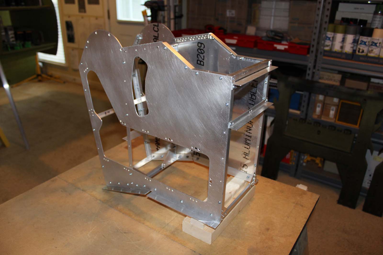
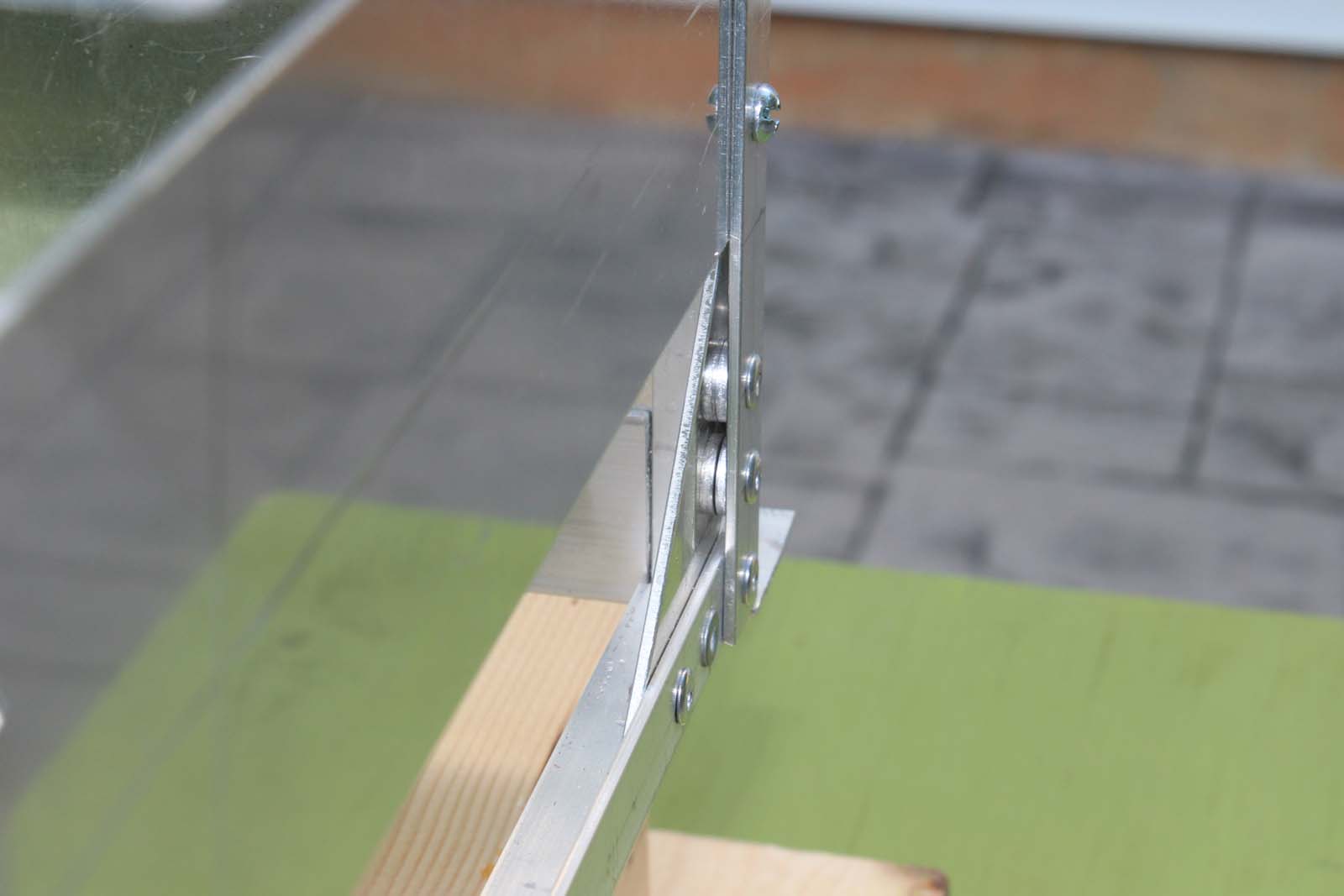
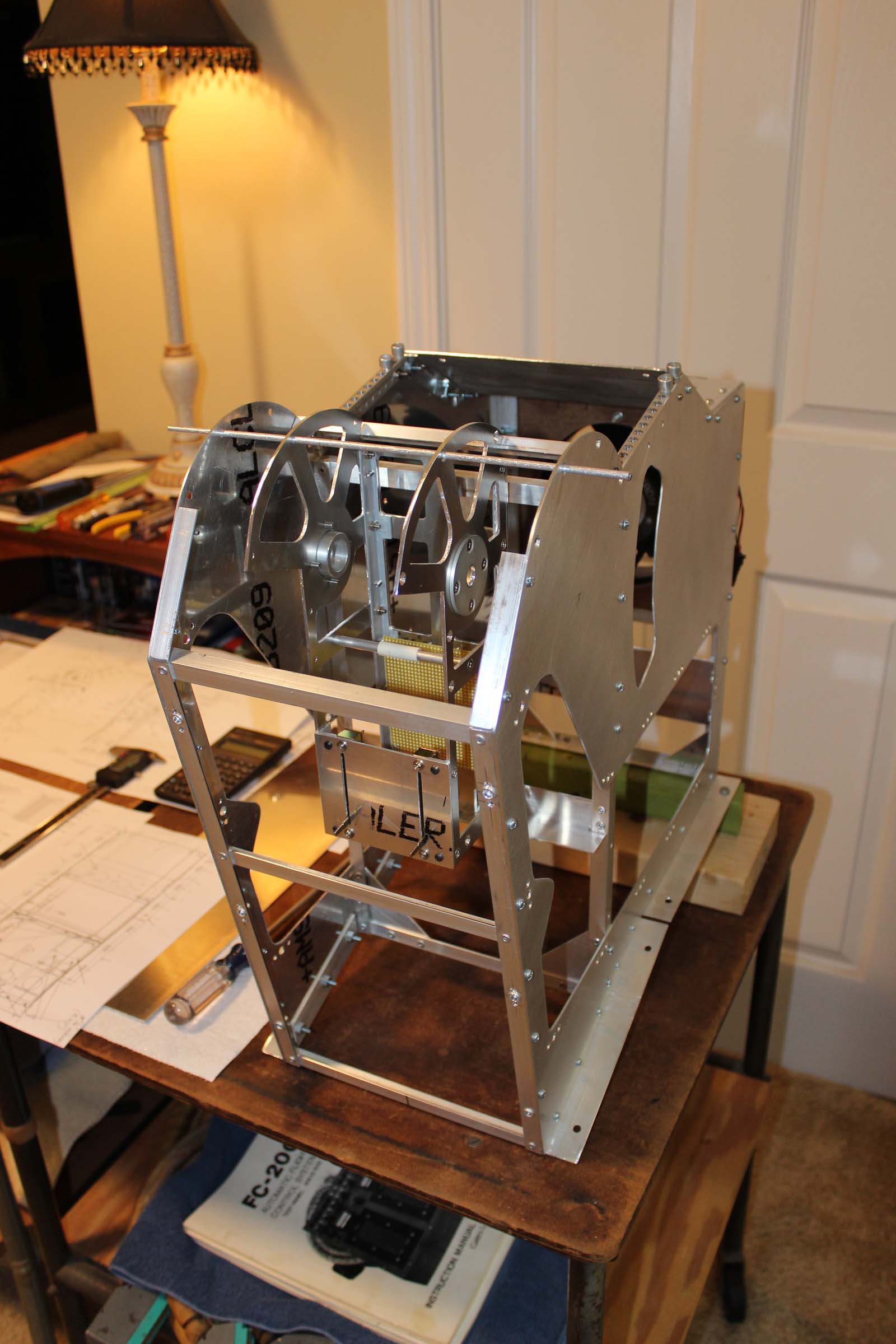
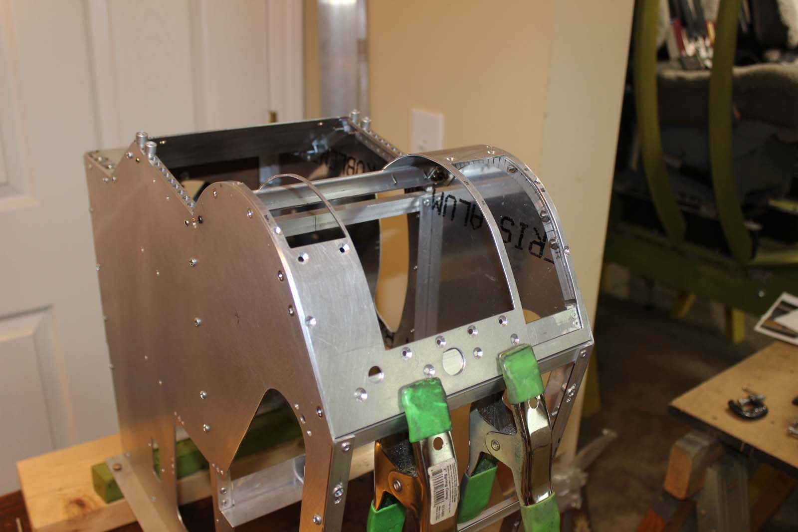
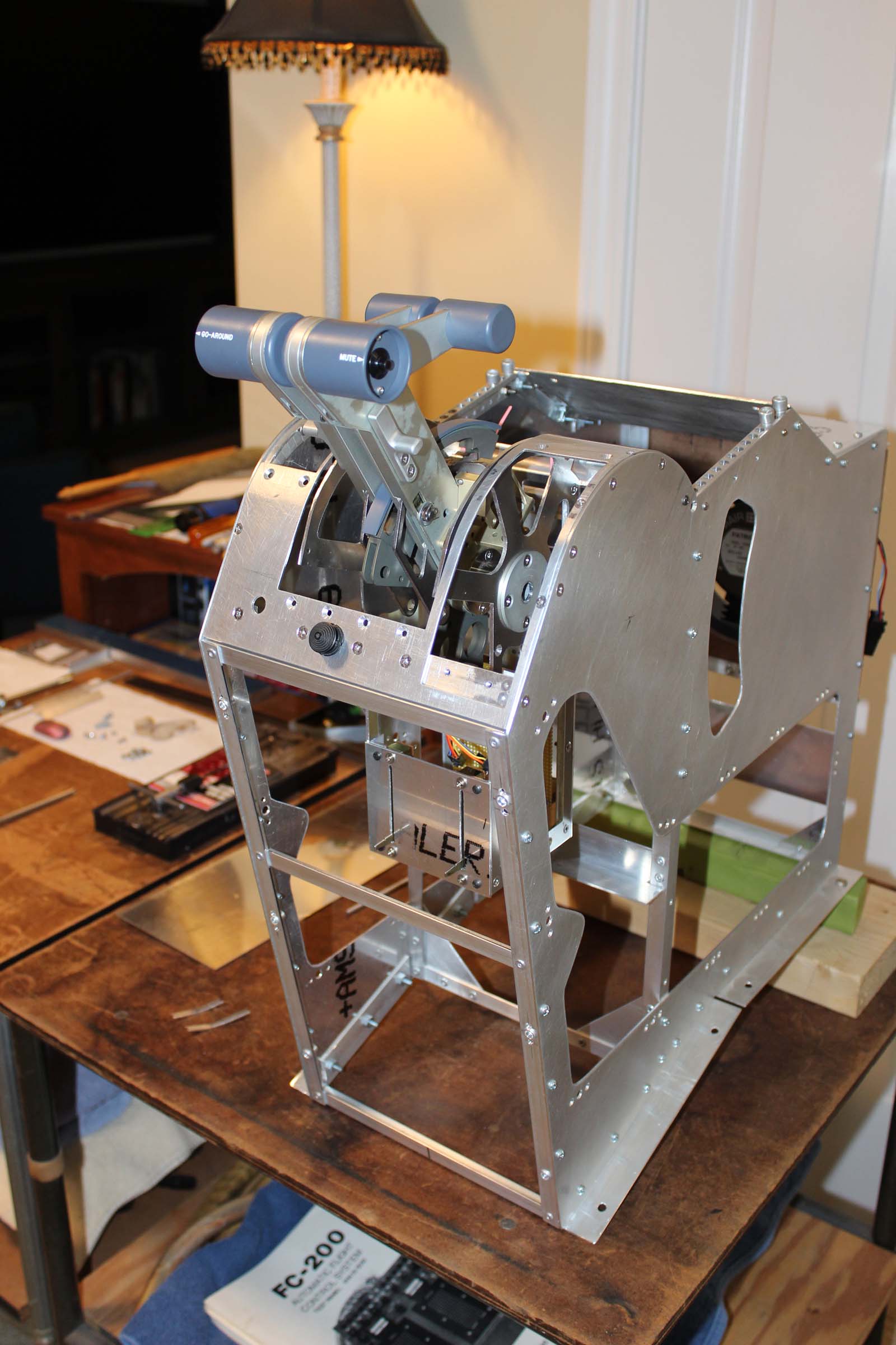
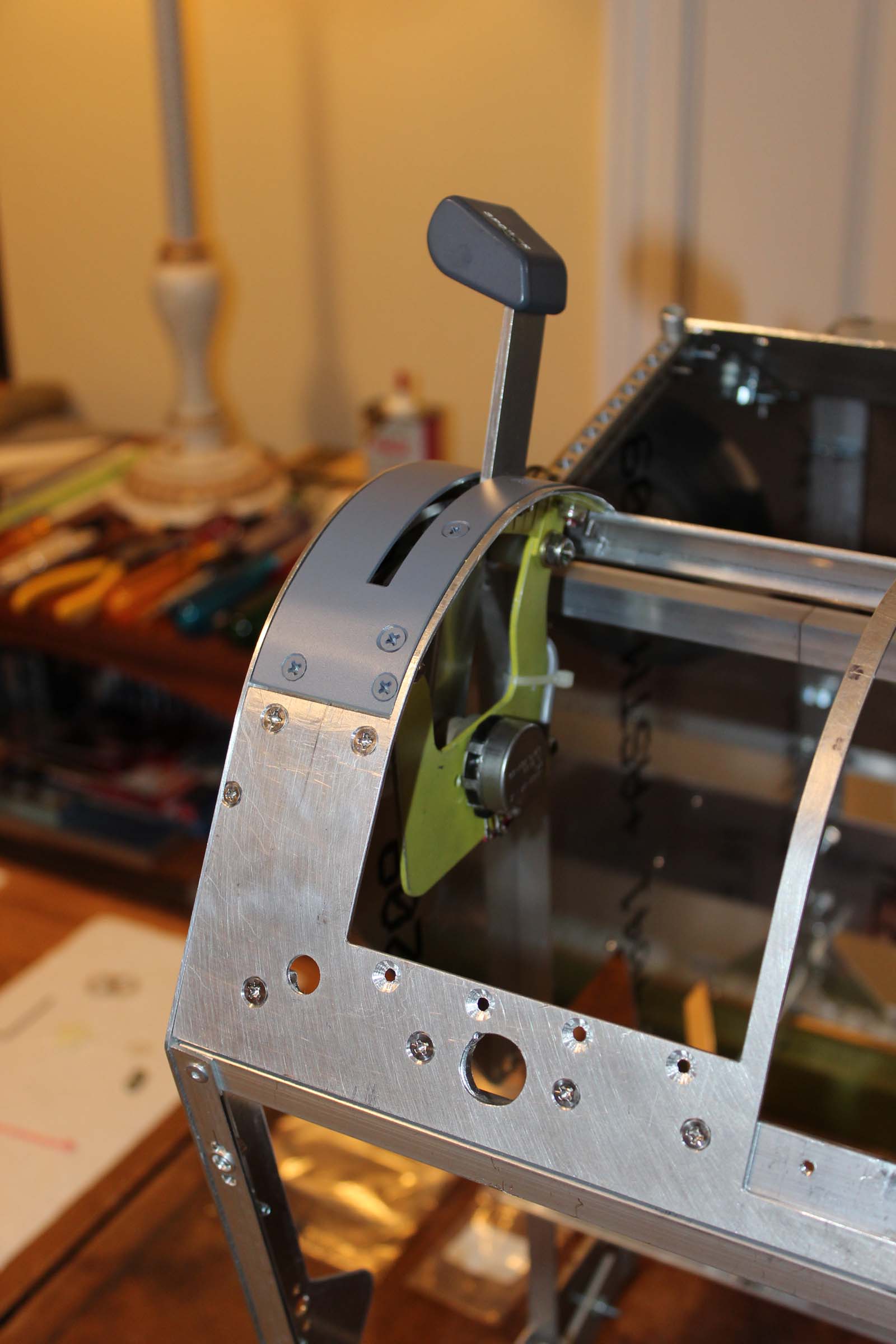
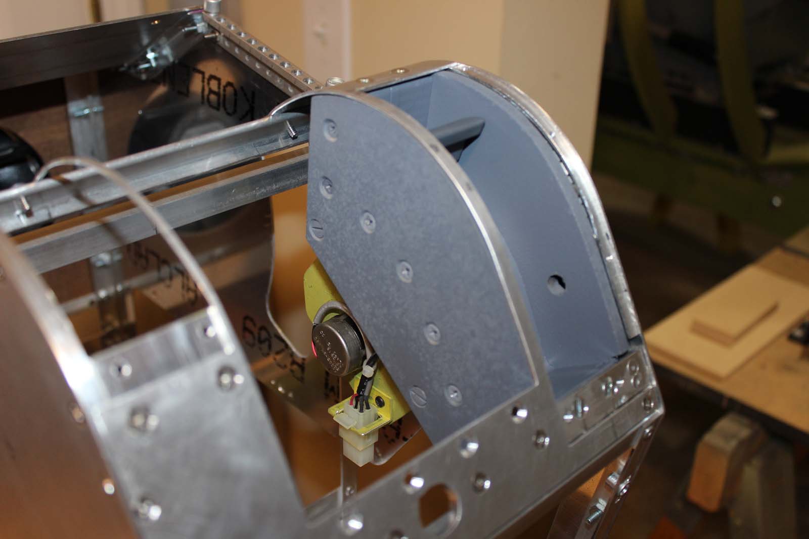
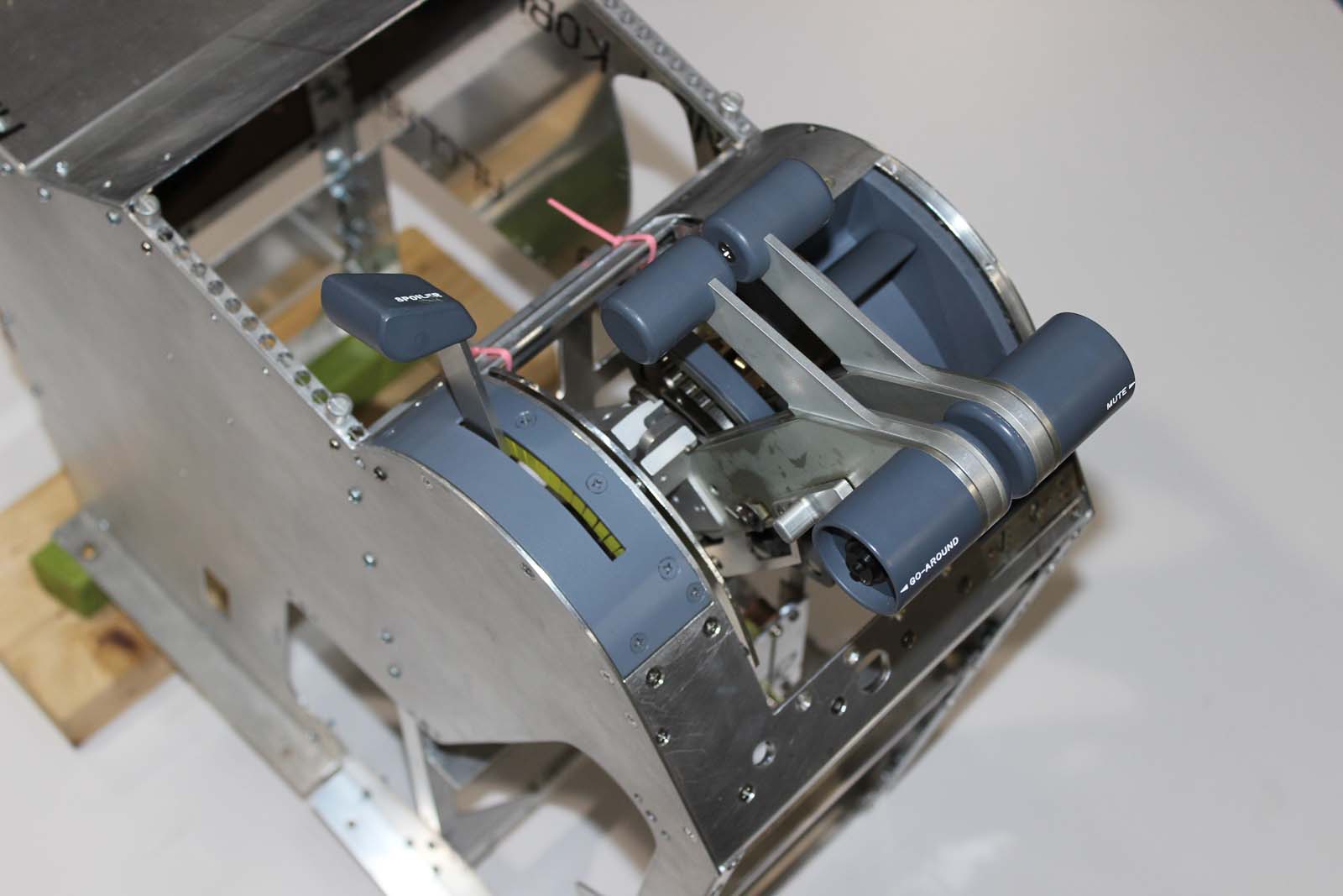
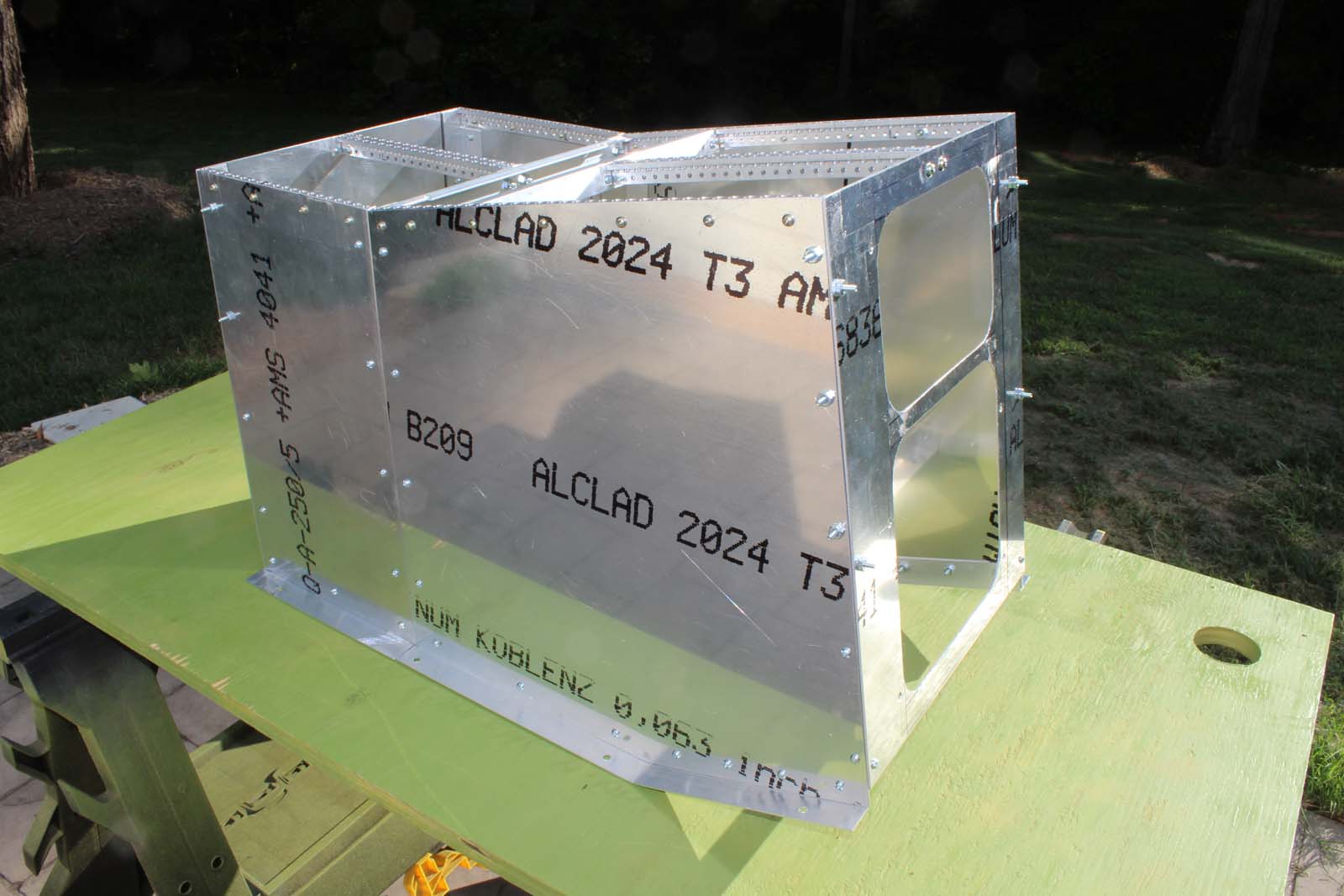
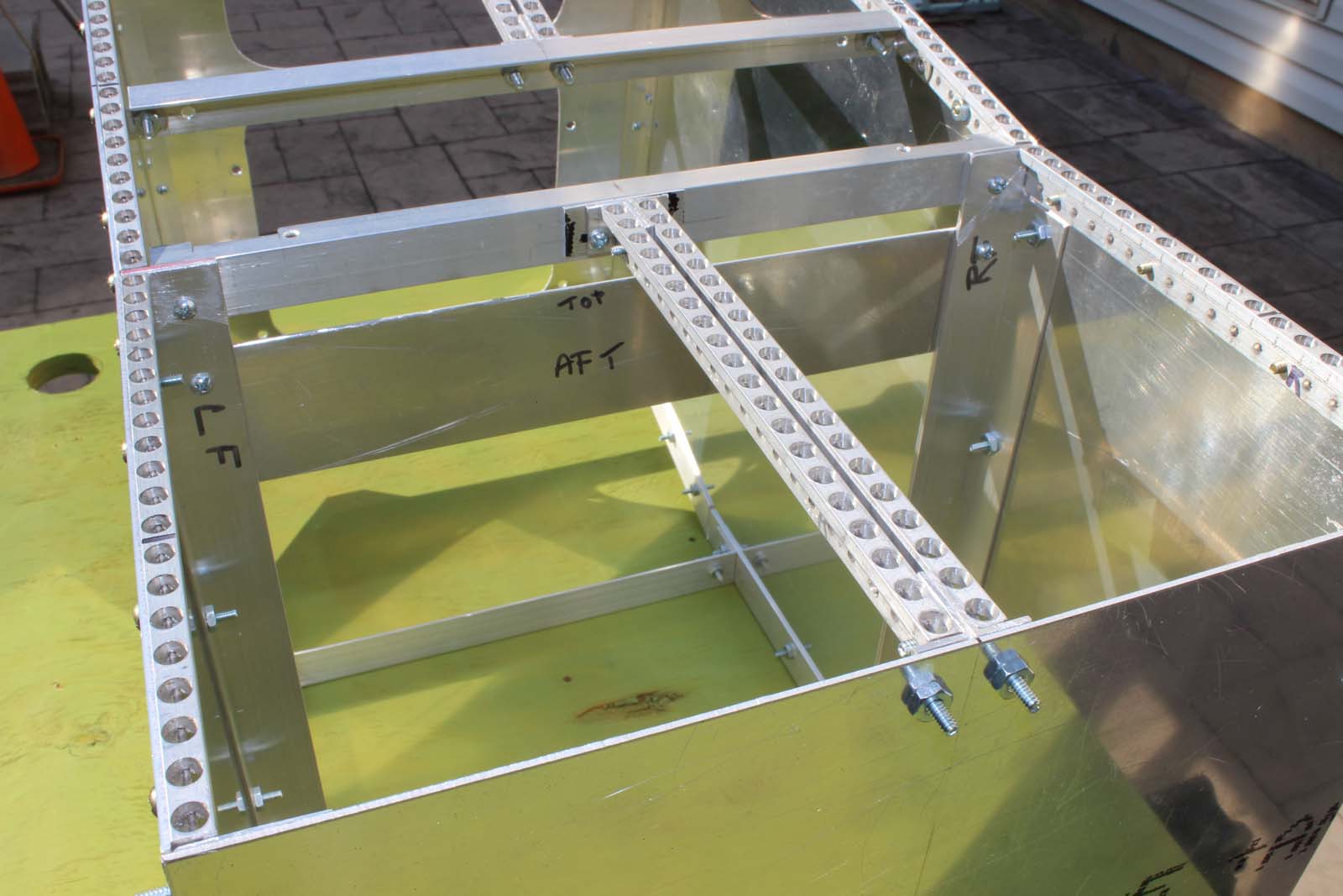
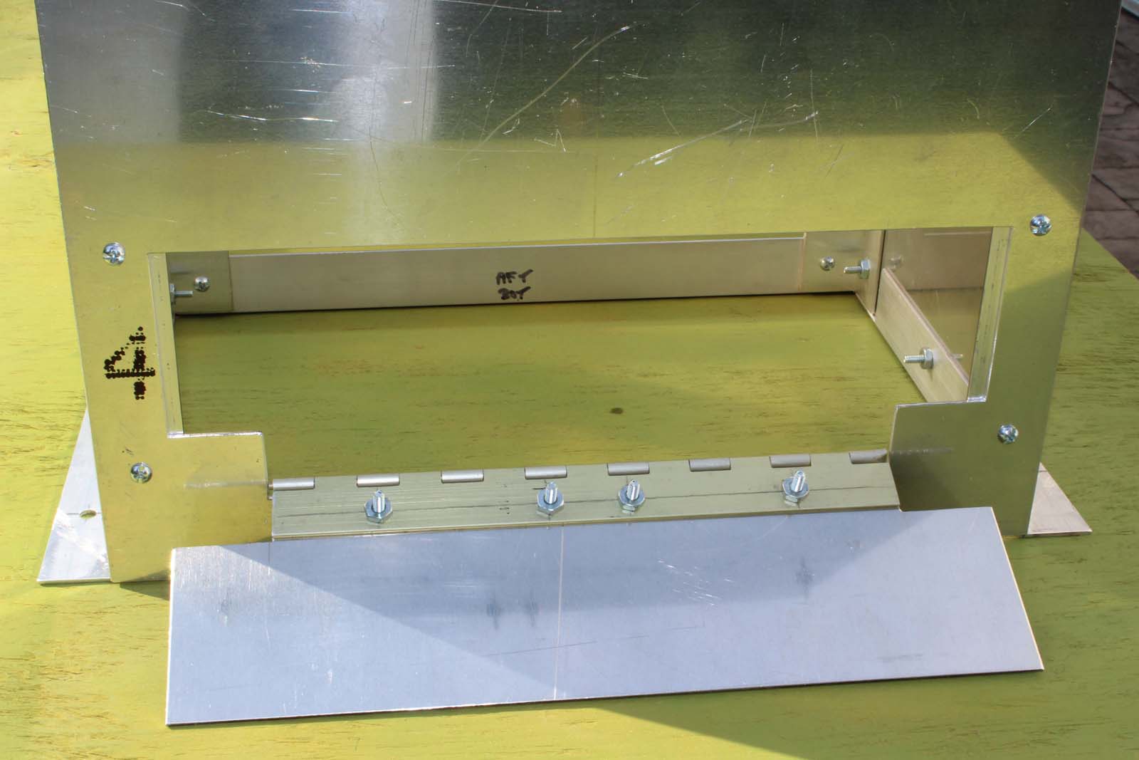
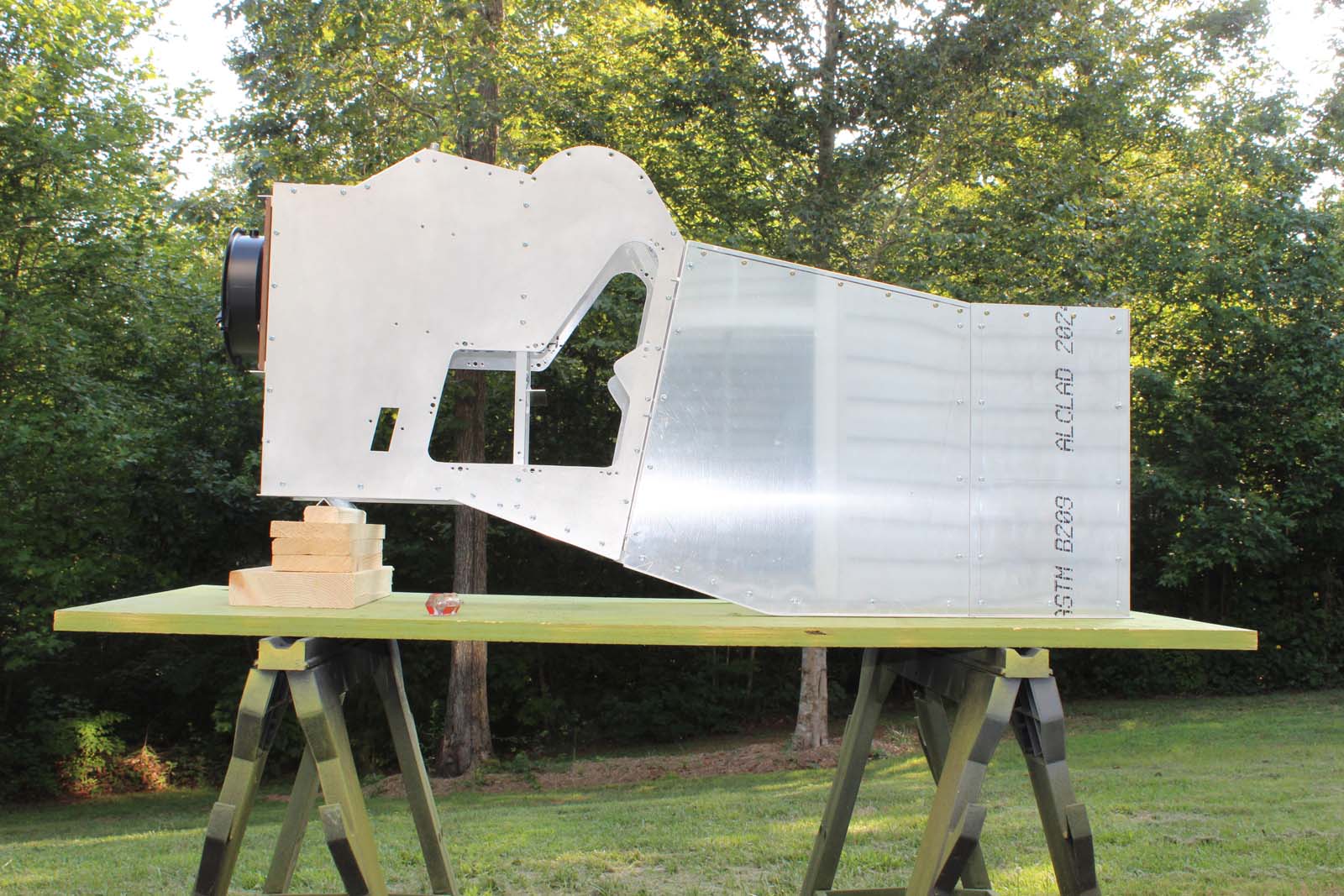
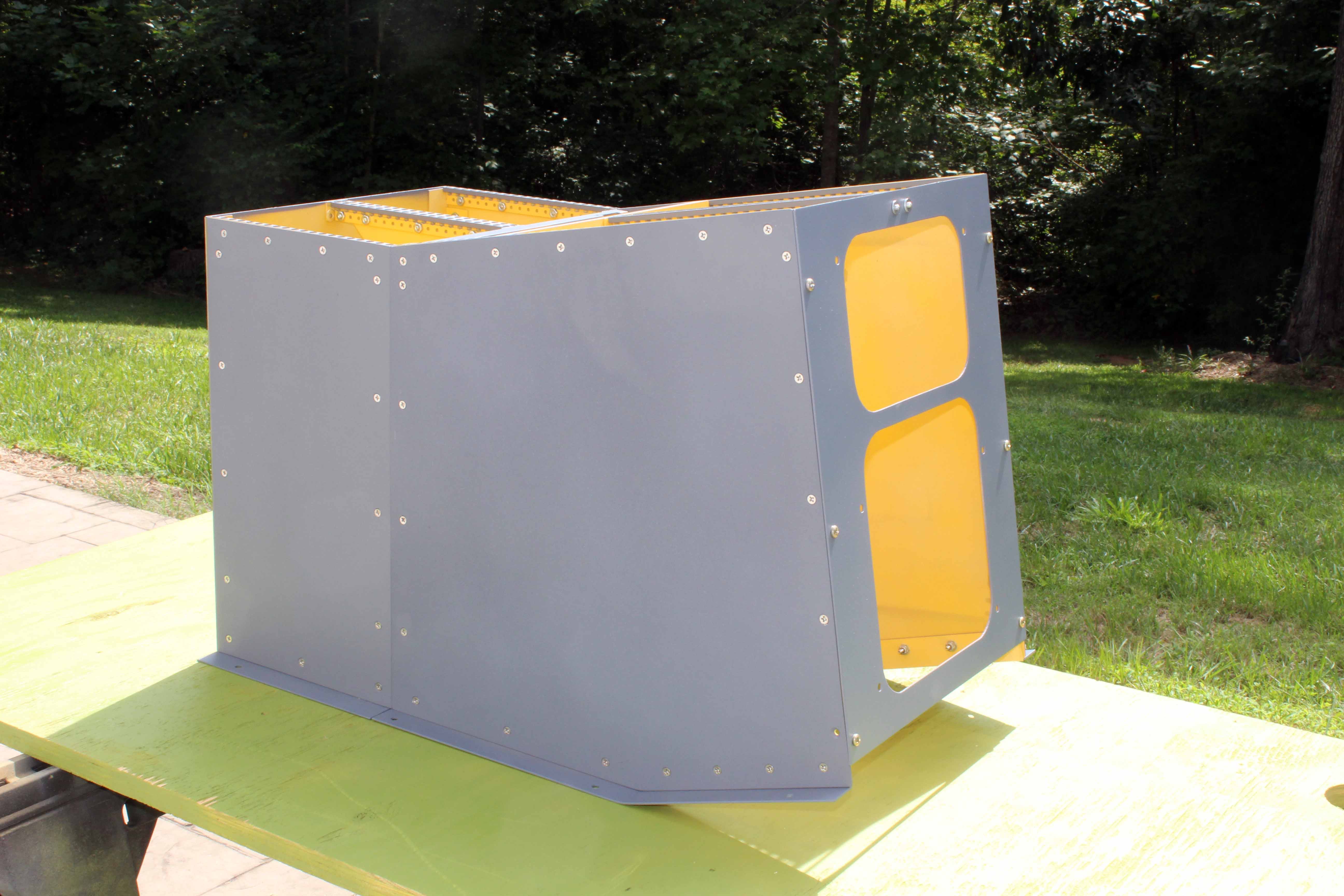
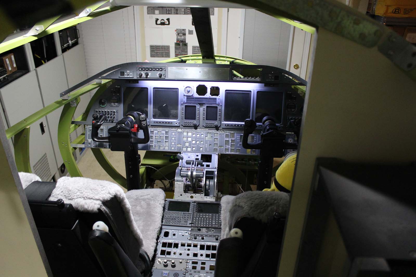
Lear 45-1001 Build History ATA Chapter 31, Indicating/Recording Systems Section -10, Instrument & Control Panels Rev 27 November 2018 The L45-1001 introduction contains useful background information on this build. If somehow you have arrived at this place and have not read the L45-1001 introduction you will find it HERE: The Lear 45 has two pedestals located in the crew compartment. They are referred to as the “Forward” pedestal and the “Center” pedestal. The center pedestal is usually equipped with an extension on the aft end to accommodate the installation of additional avionics equipment. The forward pedestal provides structural support for the thrust lever module (TLM), the spoiler control, flap control, park brake handle, elevator disconnect handle, manual gear release, and the “Test” panel. It also provides a mounting location for the MFD joystick and an avionics cooling fan. The forward pedestal is manufactured for Bombardier Learjet by Adams-Rite Corporation. The center pedestal provides structural support for many avionics controls and the engine & fuel panel. The aft extension to the center pedestal provides additional mounting locations for avionics controls. A small door on the aft end of the center pedestal provides maintenance access to various system connectors used for troubleshooting and programming. All pedestals are fabricated from aircraft alloy aluminum. They contain integrated Dzus rail which provides a standardized mounting method for avionics and other controls. I built the forward pedestal before starting on other items because the exact location of it is known from airframe drawings. Installing it prior to other items provided a “survey stake” of sorts in the cockpit from which other measurements could be located and verified. If the dimensions or location of the pedestal itself in the cockpit are in error nearly EVERYTHING else in the cockpit will be adversely affected. I worked from factory drawings to fabricate the pedestal and locate it in the crew compartment in the specified location. This is a good time to mention using aircraft alloy aluminum as a material choice. The pedestals are among items in the cockpit that must be made to correct dimensions. The decision to use aluminum was driven by the dimensional constraints of an accurate full scale cockpit. If you use a material such as wood it must be thicker than the equivalent in aluminum to obtain the necessary structural strength. Avionics and other controls that are mounted in the pedestals conform to an ARINC standardized set of dimensions. If you want panels and other items to fit properly in the pedestal you must observe those ARINC dimensions. When you do that the thickness of wood becomes an issue and the pedestals will be wider than normal. I selected aluminum for the pedestals to avoid multiple issues and dimensional conflicts with other items in the cockpit. Fabricating parts from aluminum isn’t difficult nor does it require a shop filled with expensive machinery and tooling. I believe that any sim builder with common tools and average skills can fabricate the pedestals from aluminum. I believe that because I did it successfully and I don’t think my metal-working skills are even average. You need to know a few tricks (which were taught to me many years ago by an A&P and are described in another post) and you need to have patience with the work, but most builders can make aluminum pedestals and other parts. Even so, making pedestals is not a trivial task regardless of the material you select. Ron and I have spent many hours and days working on our respective designs to make them as accurate as possible. It’s worth noting that the pedestals are separate pieces and can be removed from the airframe individually. As you complete more of your build you will find many occasions on which pulling the forward pedestal out of the way for other work is REALLY REALLY REALLY helpful. The center pedestal can also be removed separately but once the seats are installed there isn’t as much work activity in that area that requires removal of the center pedestal. Forward pedestal: The photo below was taken during an early fit test to verify that the parts of the forward pedestal fit together correctly. The pedestal is normally fastened together using rivets but for the fit tests I used 6-32 screws and nuts to allow disassembly as required. Good idea too, because I missed drilling a hole here and there and had to disassemble it. THREE TIMES….. As of the date of this writing my forward pedestal still hasn’t been painted. I’ve been busy fabricating all the stuff that goes IN the pedestal, some of which requires additional holes and brackets in the pedestal. When that work is completed I’ll paint it. Gussets are riveted in the corners to add strength to the assembly. Flat washers stacked to the same thickness as the angle aluminum make good spacers and avoid the need to flush cut the angle. An early fit test of the thrust lever module frame in the forward pedestal. IT FIT, and I don’t think anybody else could possibly be as surprised as ME! Fit test of the pedestal cover plate. The cover plate and everything installed in it must be flush because the lightplate sits flush on top of it. When the lightplate is installed all of this detail work will be hidden from view. Fit test of the thrust lever module (TLM) with the cover plate. Fit test of the spoiler control with the cover plate. Fit test of the RonnyRayRolloJones flap control with the cover plate. Fit test with the TLM, spoiler control, and flap control installed. Center pedestal: The center pedestal was originally supplied with the airframe in a short version and it quickly became obvious that aircraft operators needed more avionics space in the pedestal. An extension to the short pedestal has been fitted in some early aircraft. I do not know whether the pedestal was lengthened in later production aircraft or whether they were supplied with the extension already in place. The center pedestal in L45-1001 is made to the longer dimension as a single unit. Dzus rail is installed as an integral part of the pedestal. The maintenance access door is located at the aft end of the center pedestal. Fit test of the forward and center pedestals together. The black color item on the forward end of the forward pedestal is the avionics cooling fan. The center pedestal passed the fit test and is complete as a unit. It has been painted and is drying in the South Carolina sunshine. Fit test of the forward and center pedestals in the airframe with many of the avionics units temporarily installed. HOME: This link goes to the L45-1001 build history introduction. Links to other L45-1001 posts are found at the END of the introduction. Lear 45-1001 Build History ATA Chapter 31, Indicating/Recording Systems Section -10, Instrument & Control Panels Rev 27 November 2018 The L45-1001 introduction contains useful background information on this build. If somehow you have arrived at this place and have not read the L45-1001 introduction you will find it HERE: The Lear 45 has two pedestals located in the crew compartment. They are referred to as the “Forward” pedestal and the “Center” pedestal. The center pedestal is usually equipped with an extension on the aft end to accommodate the installation of additional avionics equipment. The forward pedestal provides structural support for the thrust lever module (TLM), the spoiler control, flap control, park brake handle, elevator disconnect handle, manual gear release, and the “Test” panel. It also provides a mounting location for the MFD joystick and an avionics cooling fan. The forward pedestal is manufactured for Bombardier Learjet by Adams-Rite Corporation. The center pedestal provides structural support for many avionics controls and the engine & fuel panel. The aft extension to the center pedestal provides additional mounting locations for avionics controls. A small door on the aft end of the center pedestal provides maintenance access to various system connectors used for troubleshooting and programming. All pedestals are fabricated from aircraft alloy aluminum. They contain integrated Dzus rail which provides a standardized mounting method for avionics and other controls. I built the forward pedestal before starting on other items because the exact location of it is known from airframe drawings. Installing it prior to other items provided a “survey stake” of sorts in the cockpit from which other measurements could be located and verified. If the dimensions or location of the pedestal itself in the cockpit are in error nearly EVERYTHING else in the cockpit will be adversely affected. I worked from factory drawings to fabricate the pedestal and locate it in the crew compartment in the specified location. This is a good time to mention using aircraft alloy aluminum as a material choice. The pedestals are among items in the cockpit that must be made to correct dimensions. The decision to use aluminum was driven by the dimensional constraints of an accurate full scale cockpit. If you use a material such as wood it must be thicker than the equivalent in aluminum to obtain the necessary structural strength. Avionics and other controls that are mounted in the pedestals conform to an ARINC standardized set of dimensions. If you want panels and other items to fit properly in the pedestal you must observe those ARINC dimensions. When you do that the thickness of wood becomes an issue and the pedestals will be wider than normal. I selected aluminum for the pedestals to avoid multiple issues and dimensional conflicts with other items in the cockpit. Fabricating parts from aluminum isn’t difficult nor does it require a shop filled with expensive machinery and tooling. I believe that any sim builder with common tools and average skills can fabricate the pedestals from aluminum. I believe that because I did it successfully and I don’t think my metal-working skills are even average. You need to know a few tricks (which were taught to me many years ago by an A&P and are described in another post) and you need to have patience with the work, but most builders can make aluminum pedestals and other parts. Even so, making pedestals is not a trivial task regardless of the material you select. Ron and I have spent many hours and days working on our respective designs to make them as accurate as possible. It’s worth noting that the pedestals are separate pieces and can be removed from the airframe individually. As you complete more of your build you will find many occasions on which pulling the forward pedestal out of the way for other work is REALLY REALLY REALLY helpful. The center pedestal can also be removed separately but once the seats are installed there isn’t as much work activity in that area that requires removal of the center pedestal. Forward pedestal: The photo below was taken during an early fit test to verify that the parts of the forward pedestal fit together correctly. The pedestal is normally fastened together using rivets but for the fit tests I used 6-32 screws and nuts to allow disassembly as required. Good idea too, because I missed drilling a hole here and there and had to disassemble it. THREE TIMES….. As of the date of this writing my forward pedestal still hasn’t been painted. I’ve been busy fabricating all the stuff that goes IN the pedestal, some of which requires additional holes and brackets in the pedestal. When that work is completed I’ll paint it. Gussets are riveted in the corners to add strength to the assembly. Flat washers stacked to the same thickness as the angle aluminum make good spacers and avoid the need to flush cut the angle. An early fit test of the thrust lever module frame in the forward pedestal. IT FIT, and I don’t think anybody else could possibly be as surprised as ME! Fit test of the pedestal cover plate. The cover plate and everything installed in it must be flush because the lightplate sits flush on top of it. When the lightplate is installed all of this detail work will be hidden from view. Fit test of the thrust lever module (TLM) with the cover plate. Fit test of the spoiler control with the cover plate. Fit test of the RonnyRayRolloJones flap control with the cover plate. Fit test with the TLM, spoiler control, and flap control installed. Center pedestal: The center pedestal was originally supplied with the airframe in a short version and it quickly became obvious that aircraft operators needed more avionics space in the pedestal. An extension to the short pedestal has been fitted in some early aircraft. I do not know whether the pedestal was lengthened in later production aircraft or whether they were supplied with the extension already in place. The center pedestal in L45-1001 is made to the longer dimension as a single unit. Dzus rail is installed as an integral part of the pedestal. The maintenance access door is located at the aft end of the center pedestal. Fit test of the forward and center pedestals together. The black color item on the forward end of the forward pedestal is the avionics cooling fan. The center pedestal passed the fit test and is complete as a unit. It has been painted and is drying in the South Carolina sunshine. Fit test of the forward and center pedestals in the airframe with many of the avionics units temporarily installed. HOME: This link goes to the L45-1001 build history introduction. Links to other L45-1001 posts are found at the END of the introduction. Nice read DonnyRay. I don't remember seeing any photos of the center pedestal until this post. Great looking pedestal. I need to look into the aft maintenance access door. I don't have one yet! Looking forward to the next chapter. Nice read DonnyRay. I don't remember seeing any photos of the center pedestal until this post. Great looking pedestal. I need to look into the aft maintenance access door. I don't have one yet! Looking forward to the next chapter.L45-1001 ATA 31-10, Pedestals
![]()
![]()
2017-10-10