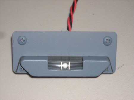
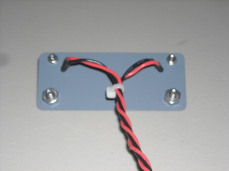
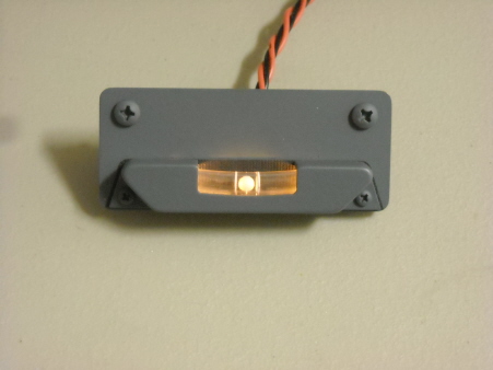
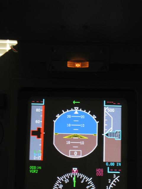
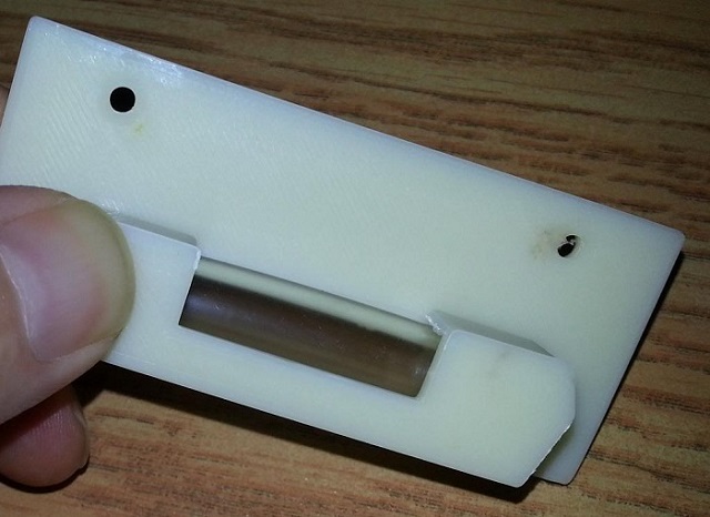
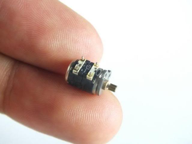
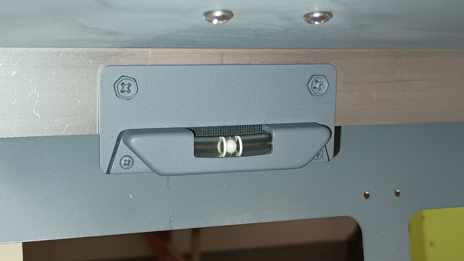
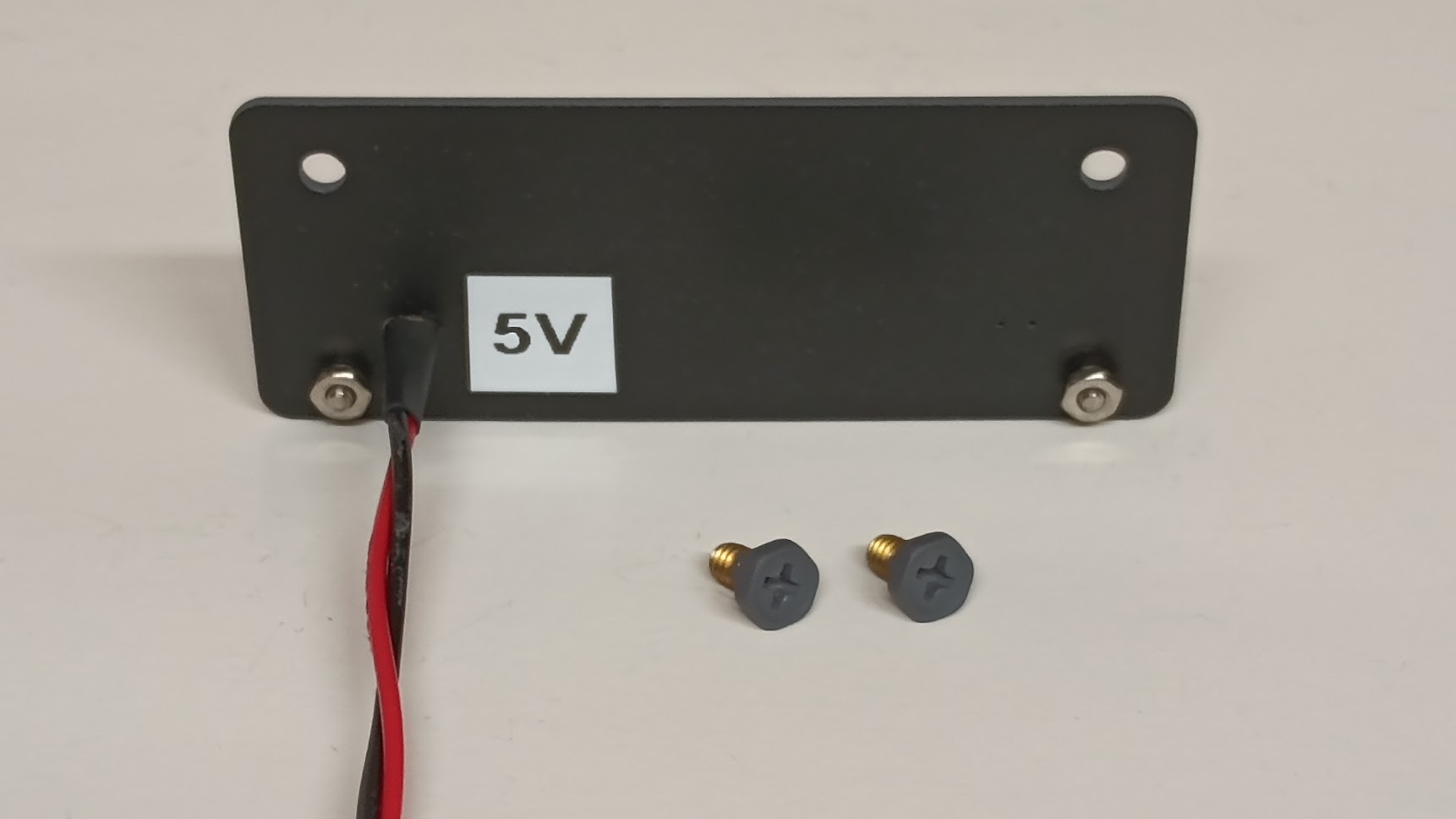
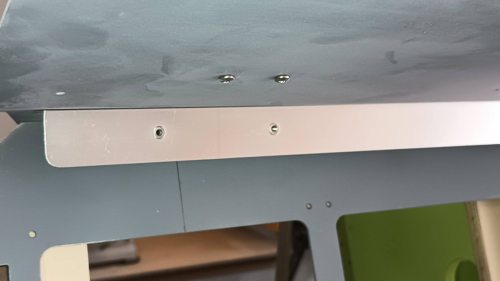
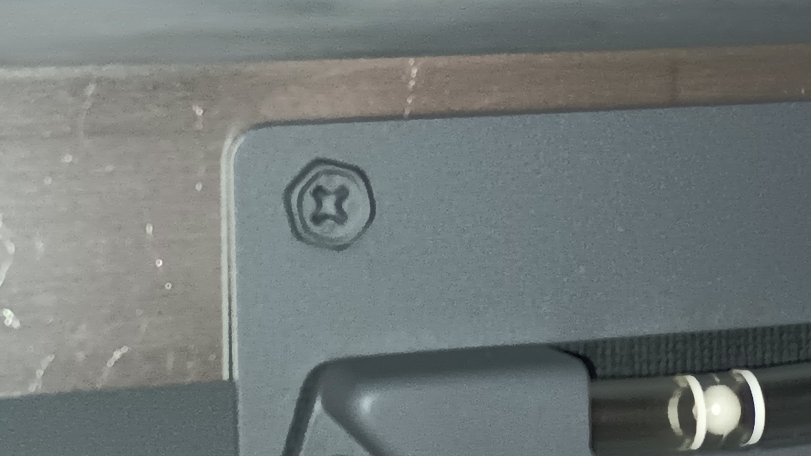
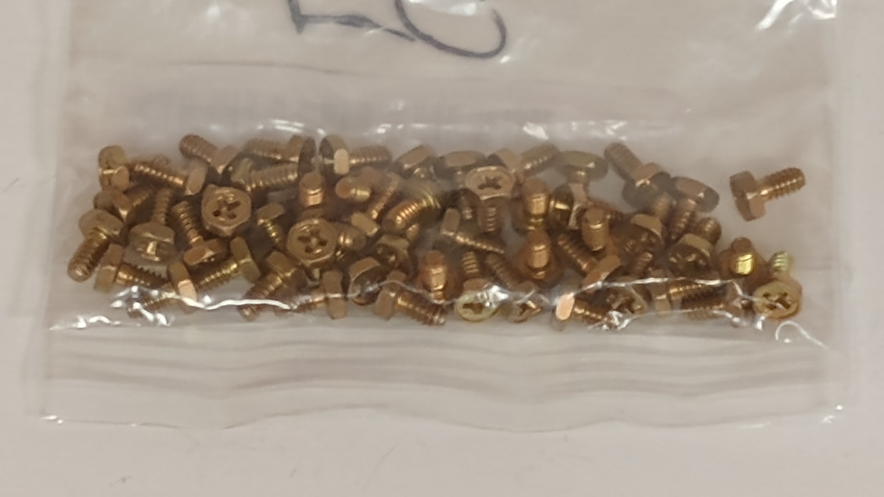
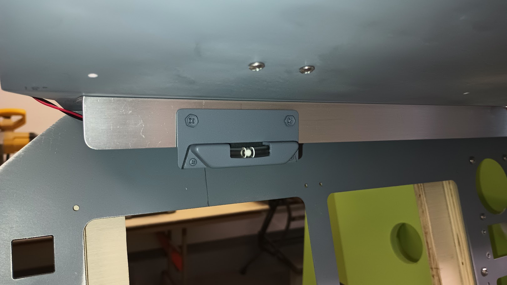
(Original thread started on 02-11-13 by Ron Rollo) I have been working on some "eye candy" for our sims, the Slip/Skid Indicators, also known as Turn Coordinators. I have to take my sim apart in the next few weeks and this is one of those little items that I wanted to add while I was in the process of rebuilding everything. Below are a couple of photos of my prototype: As you can see it lights up. Each one will have two 12 volt incandescent bulbs. But that is all it does. It is only "eye candy". The ball does not move by design. (It will indicate perfect turns no matter how bad of a pilot you are !) If we had simulators that actually had motion, then of course I would change the design to have a moving ball. Maybe later on when someone is looking for something to do, we could tackle the problem of making the ball move when the plane is in a slip or skid side ways. Until then, it's just eye candy. As long as my CNC stays up and running, I should have a few sets available in a week. I am going to initially list them at $50 each ($100 for a pair). Let me know via email if you would like a set! (Posted by DonnyRay Jones on 02-11-13) Turn coordinators don't work in simulators, with motion or not. The reason is that the force vector to which the ball responds always points toward the earth in the absence of centrifugal motion. Even motion base simulators can't make centrifugal motion. Simulators do have working SIMULATED turn coordinators. Much like a simulated AOA, the instrument is driven from calculated force vectors during turns. It will work just like a real instrument. We used to demonstrate this problem to people by tying a string and small weight to the overhead in the sim. Then go fly it. Even in steep turns that weight and string always points toward the earth. In a real airplane, of course, the string will follow the force vector generated by the turn. If you're making a coordinated turn it will point straight toward the FLOOR of the aircraft. And that's basically how a real turn coordinator works. It's just a curved level with a ball that will respond to centrifugal force generated by a turn. (Posted by Ron Rollo on 02-11-13) Hey DonnyRay, I agree with what your saying to a degree but let me ask you this: If we are in a real airplane and we turn the plane to the left in a perfectly coordinated turn, the ball in the TC will point straight down to the floor of the aircraft. Correct? However, if we are in a flight simulator with motion making that same perfectly coordinated turn, the ball will still point straight down to the floor of the sim as long as the motion system software is programed and working properly. In other words, just because we are in a motion simulator does not mean that the roll axis has to roll left because the simulator is banking and or turning left. If it is a perfectly coordinated left turn, there should be little to no motion input into the simulation meaning the TC ball will remain pointing straight down to the floor of the sim. I agree that a simple 3 or 6 D.O.F. (Degrees of Freedom) simulator can't make true centrifugal force but we can replicate it to a degree by doing nothing at all. What a 3 or 6 D.O.F. motion base sim can't replicate is negative or positive G forces beyond +1G. (with the exception of things like acceleration and deceleration by tilting forward or backwards) If we are in a turn our visual system will tell us that we are banking say 20 degrees to the left and our PFD will agree with this. However, our TC will continue to point straight down to the floor of the sim (which is correct) because or motion system would be asked to do nothing as long as our motion software is programed properly. On the other hand, if we kick the rudder over in the opposite direction then our turn will then become uncoordinated and the motion system will kick in and start to roll giving us sim pilots the sensation of slip and our TC ball will also start to slip from center. I have been lucky enough to be in a centrifuge trainer a few times during my Navy Aviation days and boy, what a treat that is. The basic idea of this training tool is to beat into our heads that you can't trust what our bodies are telling us we are doing, trust your instruments! (Posted by Will Sase on 02-12-13) Looks great Ron. In any aircraft it is important to stay balanced by using the rudder and referencing the balance-ball. The aircraft flies better, and your passengers don't redecorate the cabin with their lunches (both before and after consumption). If one day one of us builds a cabin onto a cockpit, then this will help assure our passengers that there is nothing to fear from standing up at any time, that we are so good we fly our simulators in perfect balance at all times!! (Posted by Alan Norris on 02-12-13) It's referred to as "kicking the ball" to keep it centered while turning -- thus a coordinated turn. (Posted by Terry Collins on 02-12-13) Hey Ron, I like the way you push out new components and have them available immediately. How you manage it is beyond me! (Posted by DonnyRay Jones on 02-12-13) "However, if we are in a flight simulator with motion making that same perfectly coordinated turn, the ball will still point straight down to the floor of the sim as long as the motion system software is programed and working properly." No - it won't. Do the string and weight trick - you'll see that the vector doesn't follow the floor of the motion base. It always points to the gravity vector, which is toward the earth. This is the point I was making when I said, "Simulators do have working SIMULATED turn coordinators". A SIMULATED turn coordinator is not a passive instrument. It's a driven instrument (like an AOA). A piece of software and an interface DRIVES the simulated turn coordinator to display a centered ball when making a simulated coordinated turn. I failed to include the comment that I bet we could easily make your new coordinators a DRIVEN instrument which could display properly even on a static base sim. Very nice looking work sir. (Posted by Ron Rollo on 02-12-13) Thanks again guys. Designing and working out some of these finer issues is a lot of fun for me. Almost as much fun as flying. As I come up with little things like this, I am also trying to get ahead of the curve on everything else that I offer so that I have at least one of everything in stock. Currently, the big thing that I am working on is completing two shell kits. Anyway, I have no doubt that anyone of us can find a workable solution to making these TC's work in out stationary sims. We just have to wait until we take care of the higher priority items first. DonnyRay, I think where we are having a disconnect is what I am calling the floor. There is the floor in the room of the simulator and the floor or deck of the cockpit. So this statement: "However, if we are in a flight simulator with motion making that same perfectly coordinated turn, the ball will still point straight down to the deck of the simulator as long as the motion system software is programed and working properly." To add to that statement, if the software was not working properly, the ball would only be effected by gravity and wood point straight down to the floor of the room, not the deck of the simulator. (Posted by Alan Norris on 02-14-13) Got my turn coordinator today and am well pleased. As always with parts from Ron, well engineered and beautifully made. BTW, are there any predrilled holes in the glare shield? If not, what is the correct location for it? (Posted by Ron Rollo on 02-14-13) It's mounted to the glare shield light bracket. You will need to drill two holes in the light bracket. Then you will need to drill one hole in the glareshield to run the wires up inside the glareshield. I have not looked super close but the best guess that I have is to line it up so that it is centered on the PDF Display Unit. You will also notice that the wires coming out of the back of the TC will help determine how high on the light bracket to mount it. Hold the TC as high up on the light bracket as the wires will allow. Then mark your two attachment holes. Drill, mount and your set. I hope this helps. (Posted by Alan Norris on 03-15-13) Had some spare time today so I installed and wired mine: Looks cool nice work Ron with the lights on: (Posted by Ron Rollo on 03-15-13) Thanks Alan, that looks great! I still don't have my set mounted yet. Speaking of Turn Coordinators, I am actually changing the name of this thread due to some learning I did today. This little gizmo is actually called a Slip/Skid Indicator. In some gauges the Slip/Skid Indicator is used in conjunction with a Turn Coordinator or a Turn-and-Slip Indicator which both use Gyros. Obviously the Slip/Skid Indicator uses nothing more than the force of gravity and centrifugal force. No gyros needed. (Posted by Eric Williams on 10-18-13) Since I built my sim and left the VC, my biggest annoyance is my lack of slip/skid indication. I know others here have indicated that they don't see the value in them- but for me personally, they were always critical to flying in a realistic fashion. I also always found it gave me more "immersion" because you always have a sense and awareness of how the aircraft is moving through the air- and can correct it accordingly. That said, I just found a way to make them functional using an Arduino interface card. I'll be using very small servos to drive the ball from FSX data. https://youtu.be/pdeHEoyHUK8 I figured getting the data out and a device moving was the lion's share. I think there's plenty of room to play with behind the light bracket so I thought I'd give it a go. I'm shopping for some SUPER tiny servos right now. Looks like under 5 bucks should get me a 2.5G that should work. I needed something in my hands to actually test some ideas- not exactly like Ron's yet- but should do for test "fitting" some ideas. Once I get some smaller servos to play with I should be able to clean up the design a bit and print a new one that has the rounded corners etc: I picked up a few small motors from eBay: http://www.ebay.ca/itm/2-phase-4-wire-stepper-motor-MCU-learning-Board-6mm-Canon-micro-step-motor-/171019525871?pt=LH_DefaultDomain_0&hash=item27d18edeef&_uhb=1 Will see how it goes as these will need some code tweaks. My first prototype (that I didn't show) was actually a stepper. I dismissed it due to the size of the one I have, but this deserves a revisit. Thanks Sir! Will update as I figure something out. Always open to ideas from the group. (Original thread started on 02-11-13 by Ron Rollo) I have been working on some "eye candy" for our sims, the Slip/Skid Indicators, also known as Turn Coordinators. I have to take my sim apart in the next few weeks and this is one of those little items that I wanted to add while I was in the process of rebuilding everything. Below are a couple of photos of my prototype: As you can see it lights up. Each one will have two 12 volt incandescent bulbs. But that is all it does. It is only "eye candy". The ball does not move by design. (It will indicate perfect turns no matter how bad of a pilot you are !) If we had simulators that actually had motion, then of course I would change the design to have a moving ball. Maybe later on when someone is looking for something to do, we could tackle the problem of making the ball move when the plane is in a slip or skid side ways. Until then, it's just eye candy. As long as my CNC stays up and running, I should have a few sets available in a week. I am going to initially list them at $50 each ($100 for a pair). Let me know via email if you would like a set! (Posted by DonnyRay Jones on 02-11-13) Turn coordinators don't work in simulators, with motion or not. The reason is that the force vector to which the ball responds always points toward the earth in the absence of centrifugal motion. Even motion base simulators can't make centrifugal motion. Simulators do have working SIMULATED turn coordinators. Much like a simulated AOA, the instrument is driven from calculated force vectors during turns. It will work just like a real instrument. We used to demonstrate this problem to people by tying a string and small weight to the overhead in the sim. Then go fly it. Even in steep turns that weight and string always points toward the earth. In a real airplane, of course, the string will follow the force vector generated by the turn. If you're making a coordinated turn it will point straight toward the FLOOR of the aircraft. And that's basically how a real turn coordinator works. It's just a curved level with a ball that will respond to centrifugal force generated by a turn. (Posted by Ron Rollo on 02-11-13) Hey DonnyRay, I agree with what your saying to a degree but let me ask you this: If we are in a real airplane and we turn the plane to the left in a perfectly coordinated turn, the ball in the TC will point straight down to the floor of the aircraft. Correct? However, if we are in a flight simulator with motion making that same perfectly coordinated turn, the ball will still point straight down to the floor of the sim as long as the motion system software is programed and working properly. In other words, just because we are in a motion simulator does not mean that the roll axis has to roll left because the simulator is banking and or turning left. If it is a perfectly coordinated left turn, there should be little to no motion input into the simulation meaning the TC ball will remain pointing straight down to the floor of the sim. I agree that a simple 3 or 6 D.O.F. (Degrees of Freedom) simulator can't make true centrifugal force but we can replicate it to a degree by doing nothing at all. What a 3 or 6 D.O.F. motion base sim can't replicate is negative or positive G forces beyond +1G. (with the exception of things like acceleration and deceleration by tilting forward or backwards) If we are in a turn our visual system will tell us that we are banking say 20 degrees to the left and our PFD will agree with this. However, our TC will continue to point straight down to the floor of the sim (which is correct) because or motion system would be asked to do nothing as long as our motion software is programed properly. On the other hand, if we kick the rudder over in the opposite direction then our turn will then become uncoordinated and the motion system will kick in and start to roll giving us sim pilots the sensation of slip and our TC ball will also start to slip from center. I have been lucky enough to be in a centrifuge trainer a few times during my Navy Aviation days and boy, what a treat that is. The basic idea of this training tool is to beat into our heads that you can't trust what our bodies are telling us we are doing, trust your instruments! (Posted by Will Sase on 02-12-13) Looks great Ron. In any aircraft it is important to stay balanced by using the rudder and referencing the balance-ball. The aircraft flies better, and your passengers don't redecorate the cabin with their lunches (both before and after consumption). If one day one of us builds a cabin onto a cockpit, then this will help assure our passengers that there is nothing to fear from standing up at any time, that we are so good we fly our simulators in perfect balance at all times!! (Posted by Alan Norris on 02-12-13) It's referred to as "kicking the ball" to keep it centered while turning -- thus a coordinated turn. (Posted by Terry Collins on 02-12-13) Hey Ron, I like the way you push out new components and have them available immediately. How you manage it is beyond me! (Posted by DonnyRay Jones on 02-12-13) "However, if we are in a flight simulator with motion making that same perfectly coordinated turn, the ball will still point straight down to the floor of the sim as long as the motion system software is programed and working properly." No - it won't. Do the string and weight trick - you'll see that the vector doesn't follow the floor of the motion base. It always points to the gravity vector, which is toward the earth. This is the point I was making when I said, "Simulators do have working SIMULATED turn coordinators". A SIMULATED turn coordinator is not a passive instrument. It's a driven instrument (like an AOA). A piece of software and an interface DRIVES the simulated turn coordinator to display a centered ball when making a simulated coordinated turn. I failed to include the comment that I bet we could easily make your new coordinators a DRIVEN instrument which could display properly even on a static base sim. Very nice looking work sir. (Posted by Ron Rollo on 02-12-13) Thanks again guys. Designing and working out some of these finer issues is a lot of fun for me. Almost as much fun as flying. As I come up with little things like this, I am also trying to get ahead of the curve on everything else that I offer so that I have at least one of everything in stock. Currently, the big thing that I am working on is completing two shell kits. Anyway, I have no doubt that anyone of us can find a workable solution to making these TC's work in out stationary sims. We just have to wait until we take care of the higher priority items first. DonnyRay, I think where we are having a disconnect is what I am calling the floor. There is the floor in the room of the simulator and the floor or deck of the cockpit. So this statement: "However, if we are in a flight simulator with motion making that same perfectly coordinated turn, the ball will still point straight down to the deck of the simulator as long as the motion system software is programed and working properly." To add to that statement, if the software was not working properly, the ball would only be effected by gravity and wood point straight down to the floor of the room, not the deck of the simulator. (Posted by Alan Norris on 02-14-13) Got my turn coordinator today and am well pleased. As always with parts from Ron, well engineered and beautifully made. BTW, are there any predrilled holes in the glare shield? If not, what is the correct location for it? (Posted by Ron Rollo on 02-14-13) It's mounted to the glare shield light bracket. You will need to drill two holes in the light bracket. Then you will need to drill one hole in the glareshield to run the wires up inside the glareshield. I have not looked super close but the best guess that I have is to line it up so that it is centered on the PDF Display Unit. You will also notice that the wires coming out of the back of the TC will help determine how high on the light bracket to mount it. Hold the TC as high up on the light bracket as the wires will allow. Then mark your two attachment holes. Drill, mount and your set. I hope this helps. (Posted by Alan Norris on 03-15-13) Had some spare time today so I installed and wired mine: Looks cool nice work Ron with the lights on: (Posted by Ron Rollo on 03-15-13) Thanks Alan, that looks great! I still don't have my set mounted yet. Speaking of Turn Coordinators, I am actually changing the name of this thread due to some learning I did today. This little gizmo is actually called a Slip/Skid Indicator. In some gauges the Slip/Skid Indicator is used in conjunction with a Turn Coordinator or a Turn-and-Slip Indicator which both use Gyros. Obviously the Slip/Skid Indicator uses nothing more than the force of gravity and centrifugal force. No gyros needed. (Posted by Eric Williams on 10-18-13) Since I built my sim and left the VC, my biggest annoyance is my lack of slip/skid indication. I know others here have indicated that they don't see the value in them- but for me personally, they were always critical to flying in a realistic fashion. I also always found it gave me more "immersion" because you always have a sense and awareness of how the aircraft is moving through the air- and can correct it accordingly. That said, I just found a way to make them functional using an Arduino interface card. I'll be using very small servos to drive the ball from FSX data. I figured getting the data out and a device moving was the lion's share. I think there's plenty of room to play with behind the light bracket so I thought I'd give it a go. I'm shopping for some SUPER tiny servos right now. Looks like under 5 bucks should get me a 2.5G that should work. I needed something in my hands to actually test some ideas- not exactly like Ron's yet- but should do for test "fitting" some ideas. Once I get some smaller servos to play with I should be able to clean up the design a bit and print a new one that has the rounded corners etc: I picked up a few small motors from eBay: Will see how it goes as these will need some code tweaks. My first prototype (that I didn't show) was actually a stepper. I dismissed it due to the size of the one I have, but this deserves a revisit. Thanks Sir! Will update as I figure something out. Always open to ideas from the group. Hey guys, I have been updating the nitty gritty items in the sim and today it's the Slip/Skid Indicators or otherwise known as the Turn Coordinators. These are still static displays and do not do anything other than look good, however, what has changed is the way they light up. My previous version used 12v incandescent mini bulbs. This new version uses SMD LEDs in conjunction with SMD resistors and 5v power. One thing we have discovered is incandescent bulbs tend to and are more likely to put out interference. (This is certainly the case with some versions of the real CDUs using incandescent bulbs) This is most likely not the case with the previous version of the Slip/Skid Indicators but in an effort to make improvements, moving to LEDs is the way to go. Below is the left side Slip/Skid Indicator mounted to the lamp shade rail. I took advantage of the clad and designed a short circuit (no pun intended) that enables me to reduce the wires coming off the back by half. Also note that these Slip/Skid Indicators are designed to use 5v power just like all the other panels. (They can handle up to 12v) Another small improvement in this area was the addition of Rivnuts to the lamp shade rail. They are size 6-32. Using Rivnuts enables us to precisely locate the position the Slip/Skid Indicators need to be in for mounting. And more importantly, insure they are perfectly level. While doing my research, I discovered that the mounting screws are not actually screws, they are bolts. Special bolts. A hex bolt with a Phillips drive in the center. Not knowing exactly what I was looking for, it appeared that these would be very difficult to find. But once you know what you are looking for, they are fairly easy to find. Turns out they are only found in real aviation and are known as "National Aerospace Standard NAS1801-06-4 Steel Screw, Machine" I snagged enough for anyone who needs a couple sets. These are the tiny details that add to the overall flightsim experience and helps boost the impression you are in an actual aircraft flying somewhere! Again, this design is not a working model. It is a static display and acts as high end "eye candy"! Jason and I have discussed the possibilities of making a working version which is certainly possible. I am sure that in the future we will revisit this area again and see if we can finally get a working model sorted out. In the meantime, nothing but perfectly coordinated turns indicated! Hey guys, I have been updating the nitty gritty items in the sim and today it's the Slip/Skid Indicators or otherwise known as the Turn Coordinators. These are still static displays and do not do anything other than look good, however, what has changed is the way they light up. My previous version used 12v incandescent mini bulbs. This new version uses SMD LEDs in conjunction with SMD resistors and 5v power. One thing we have discovered is incandescent bulbs tend to and are more likely to put out interference. (This is certainly the case with some versions of the real CDUs using incandescent bulbs) This is most likely not the case with the previous version of the Slip/Skid Indicators but in an effort to make improvements, moving to LEDs is the way to go. Below is the left side Slip/Skid Indicator mounted to the lamp shade rail. I took advantage of the clad and designed a short circuit (no pun intended) that enables me to reduce the wires coming off the back by half. Also note that these Slip/Skid Indicators are designed to use 5v power just like all the other panels. (They can handle up to 12v) Another small improvement in this area was the addition of Rivnuts to the lamp shade rail. They are size 6-32. Using Rivnuts enables us to precisely locate the position the Slip/Skid Indicators need to be in for mounting. And more importantly, insure they are perfectly level. While doing my research, I discovered that the mounting screws are not actually screws, they are bolts. Special bolts. A hex bolt with a Phillips drive in the center. Not knowing exactly what I was looking for, it appeared that these would be very difficult to find. But once you know what you are looking for, they are fairly easy to find. Turns out they are only found in real aviation and are known as "National Aerospace Standard NAS1801-06-4 Steel Screw, Machine" I snagged enough for anyone who needs a couple sets. These are the tiny details that add to the overall flightsim experience and helps boost the impression you are in an actual aircraft flying somewhere! Again, this design is not a working model. It is a static display and acts as high end "eye candy"! Jason and I have discussed the possibilities of making a working version which is certainly possible. I am sure that in the future we will revisit this area again and see if we can finally get a working model sorted out. In the meantime, nothing but perfectly coordinated turns indicated! Slip/Skid Indicator Discussion
![]()














2017-10-10


