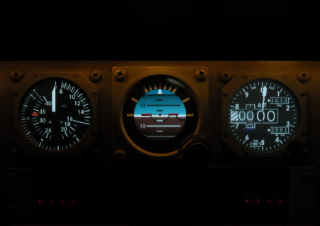
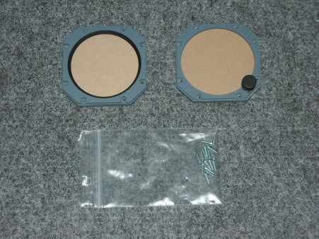
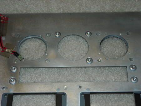
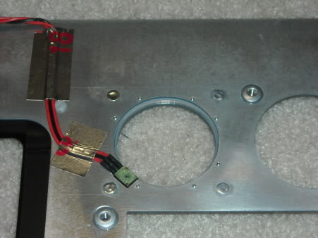
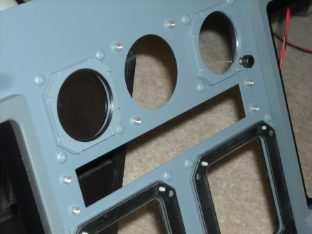
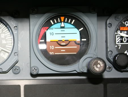
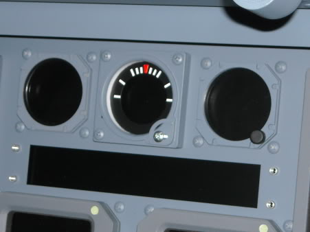
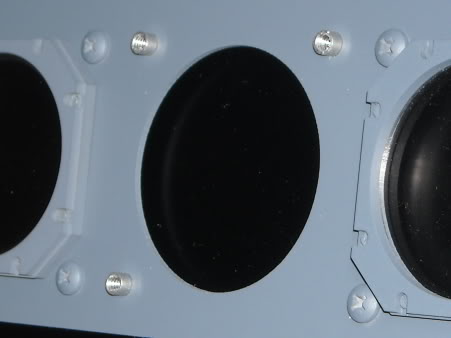
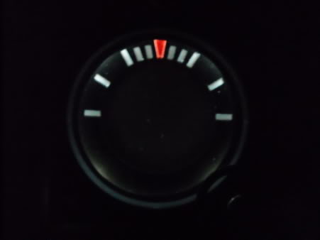
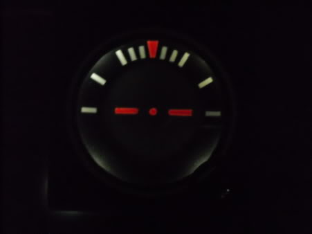
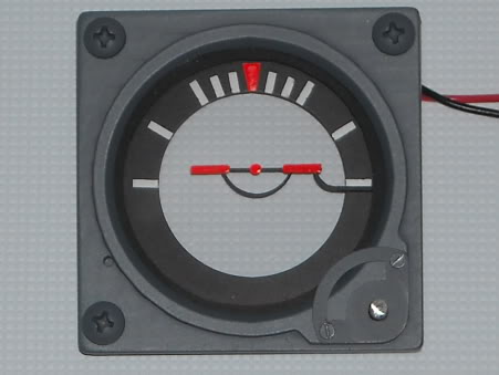
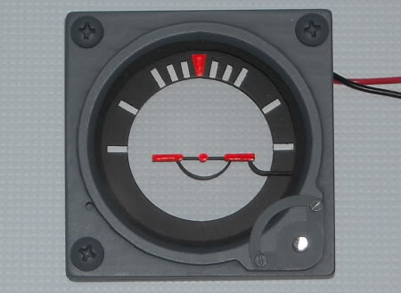
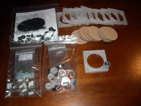
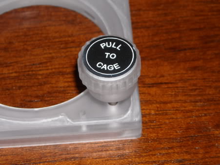
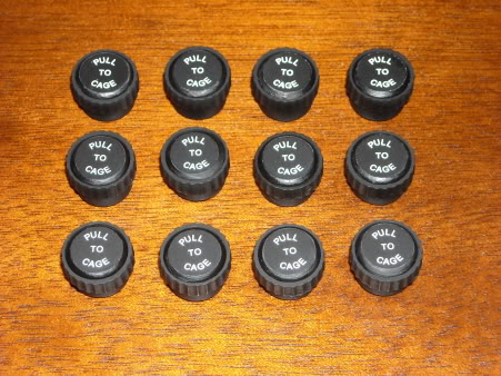
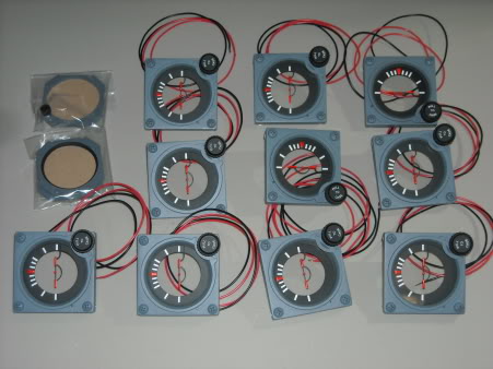
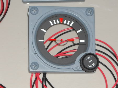
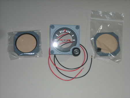
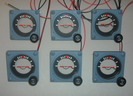
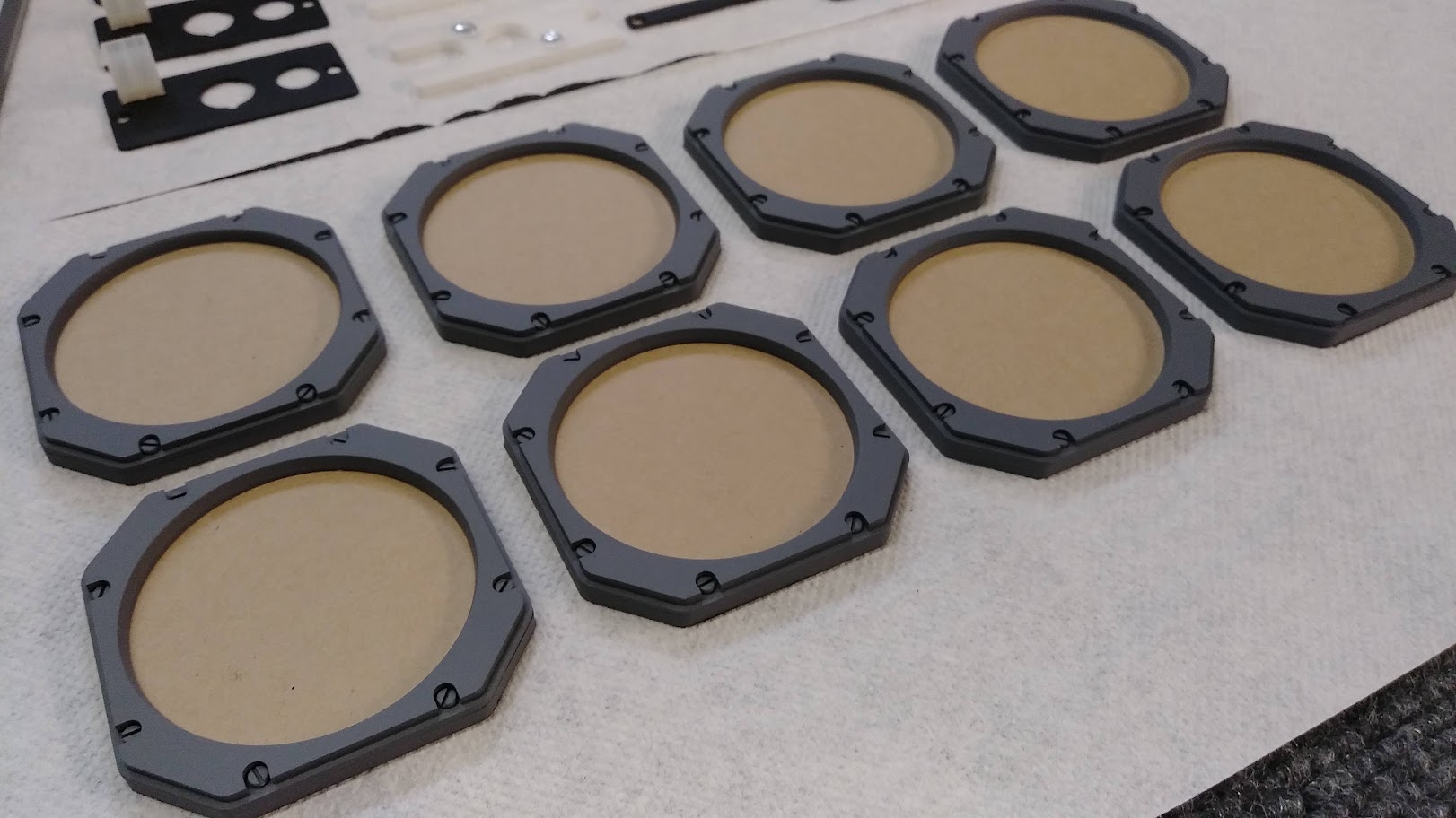
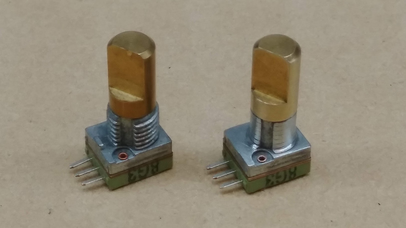
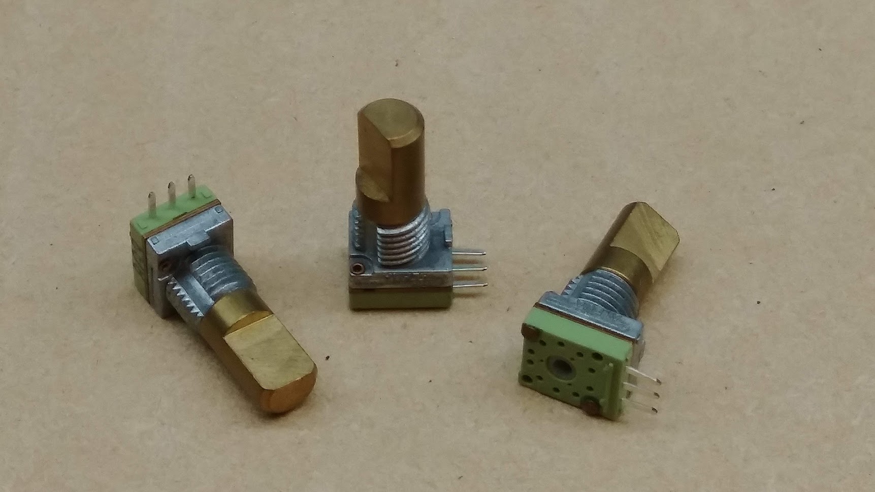
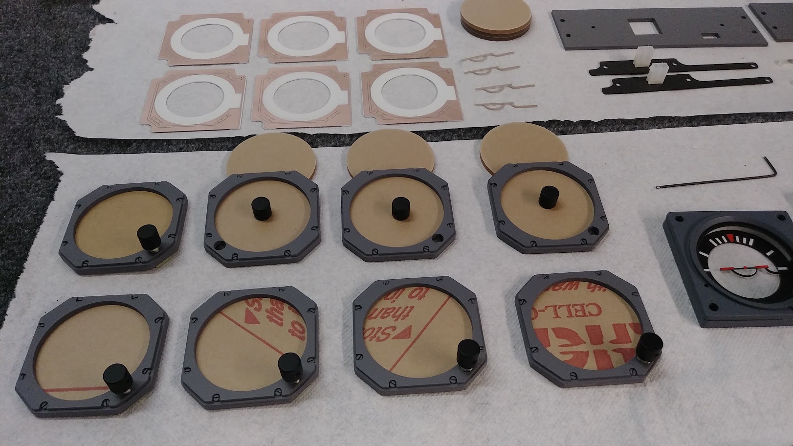
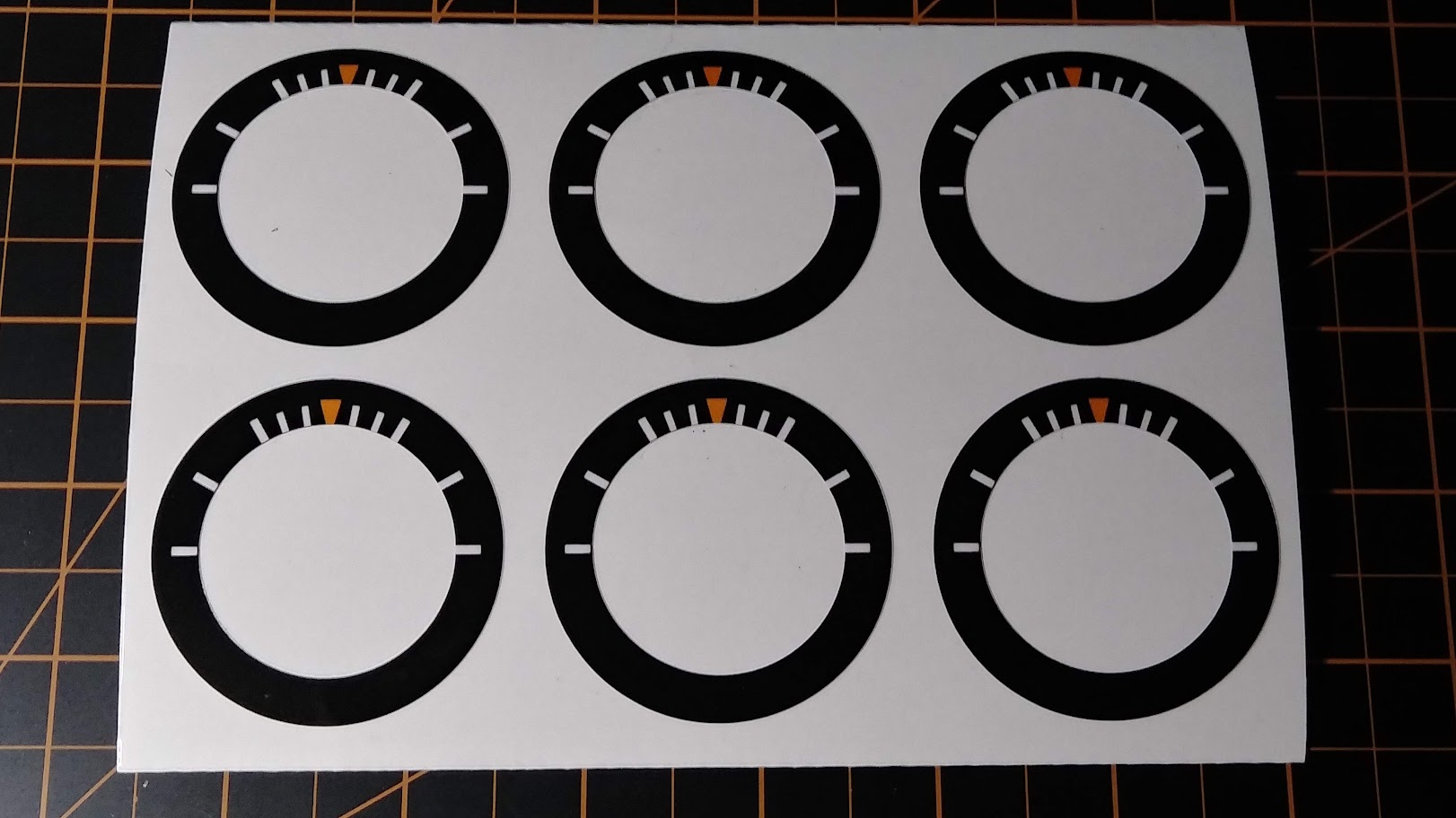
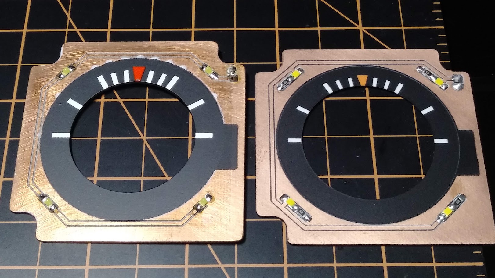
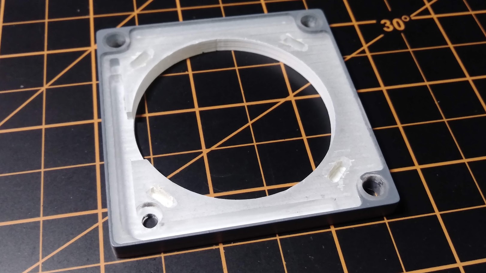
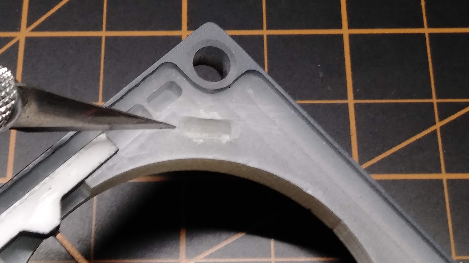
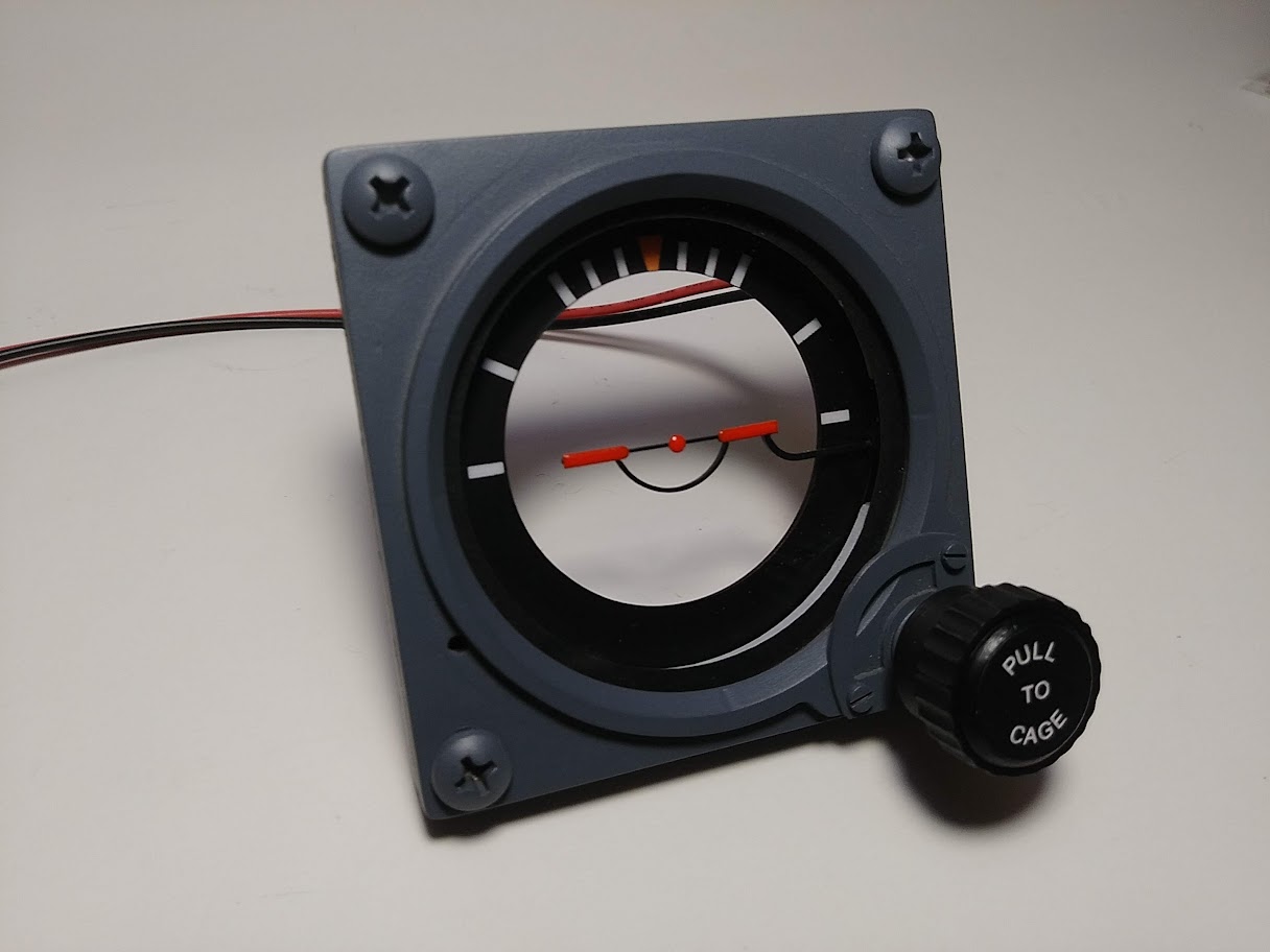
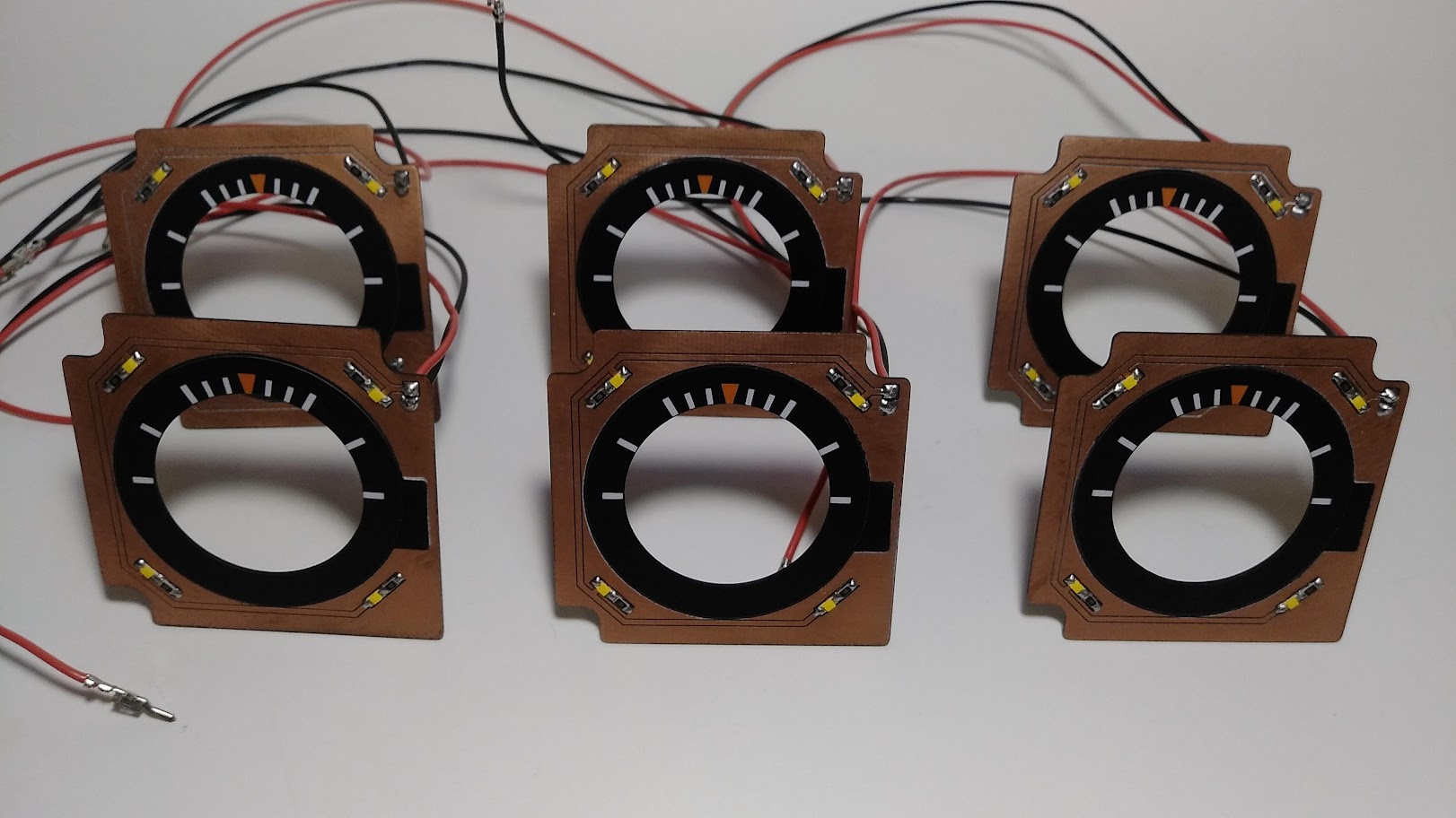
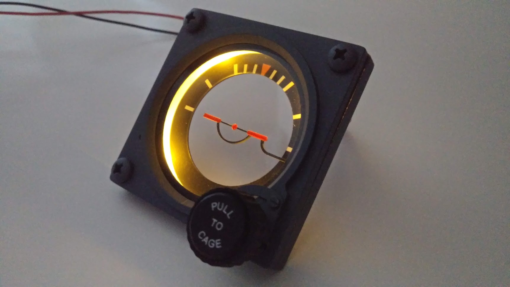
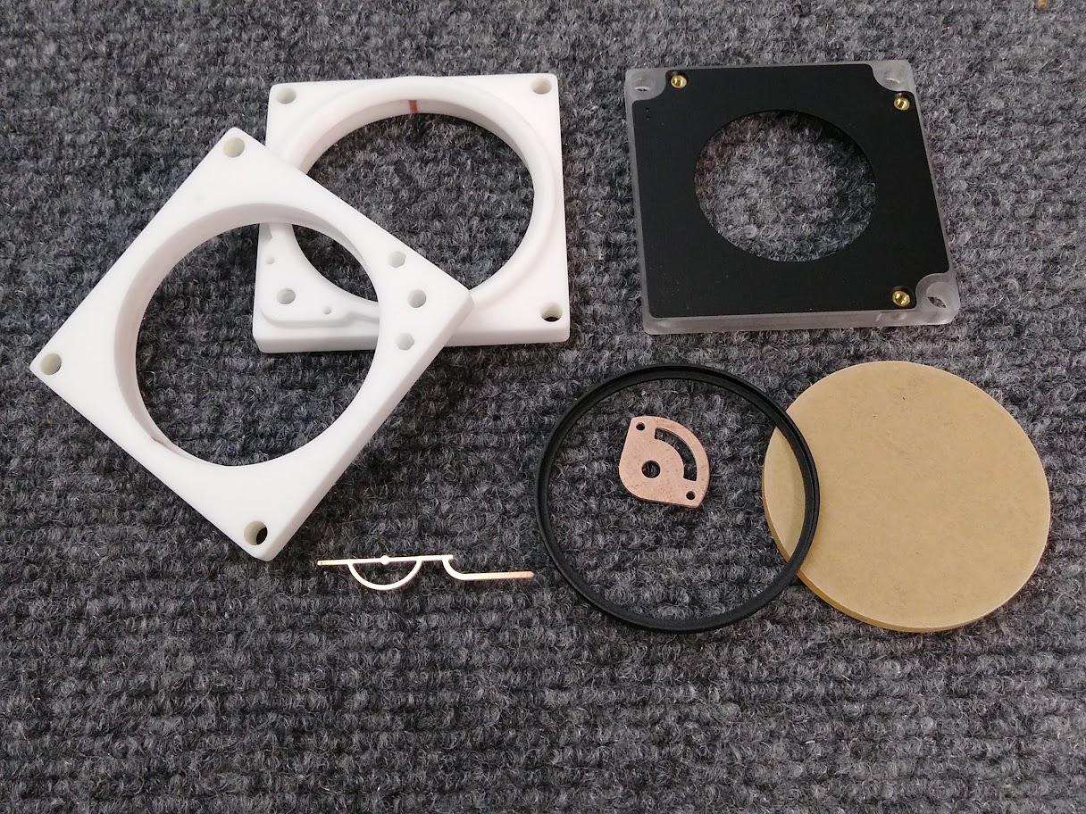
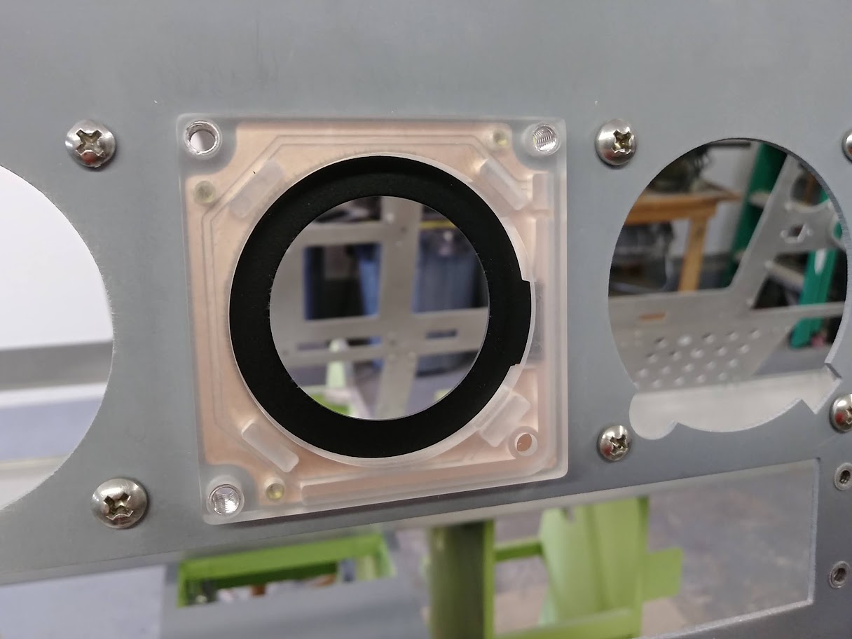
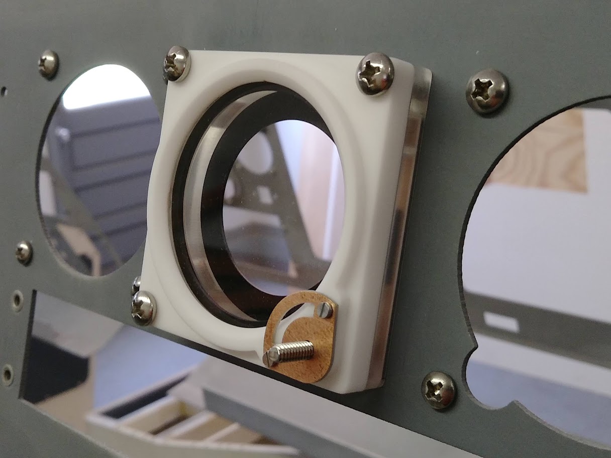
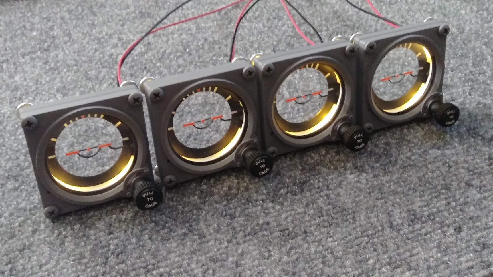
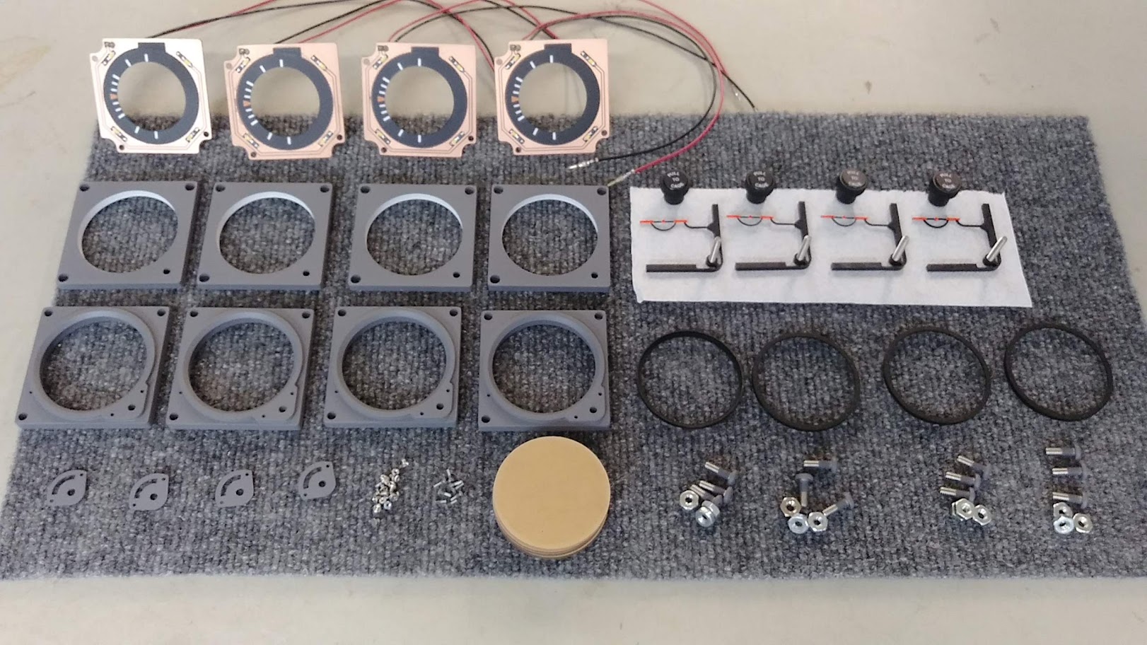
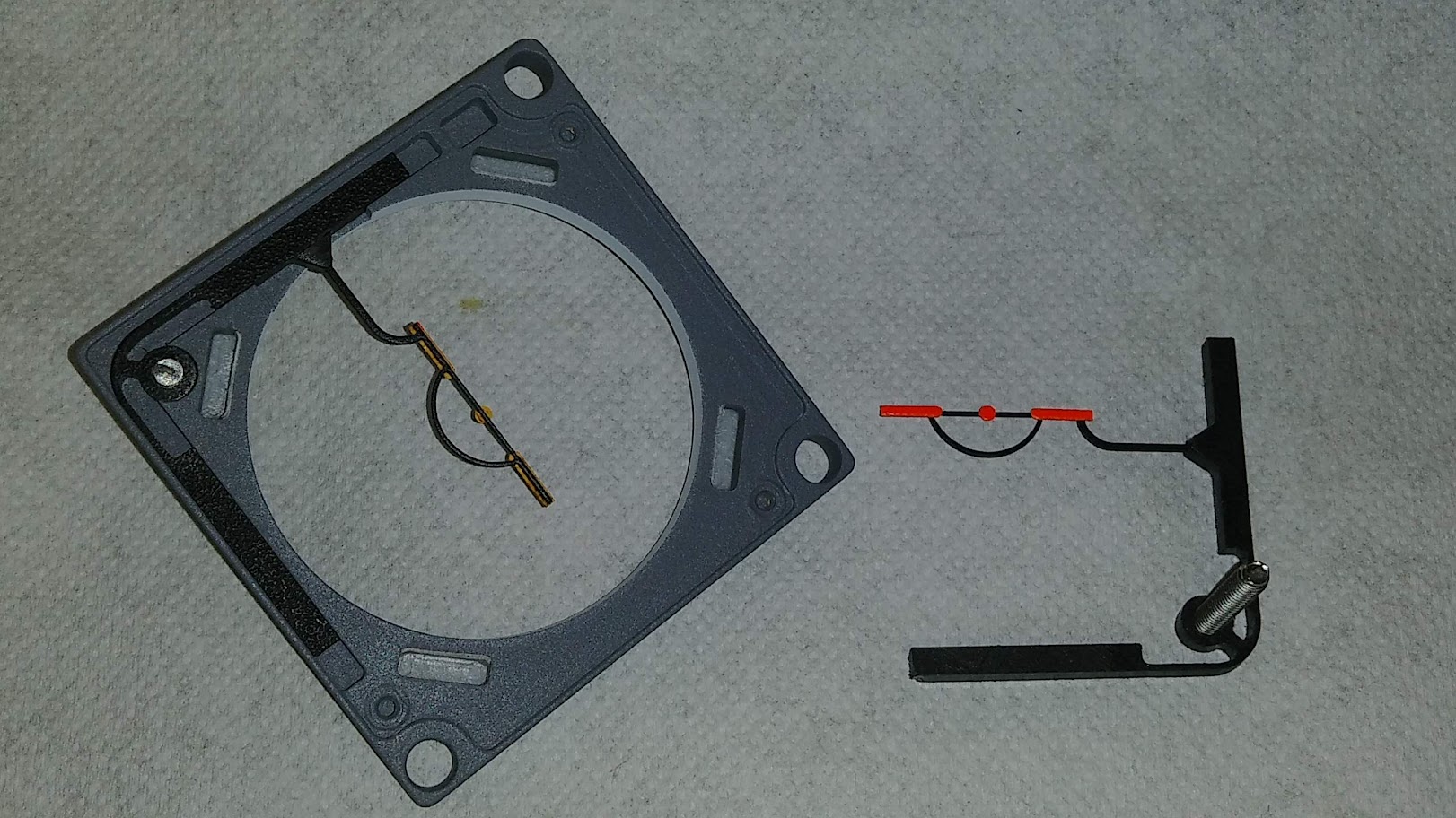
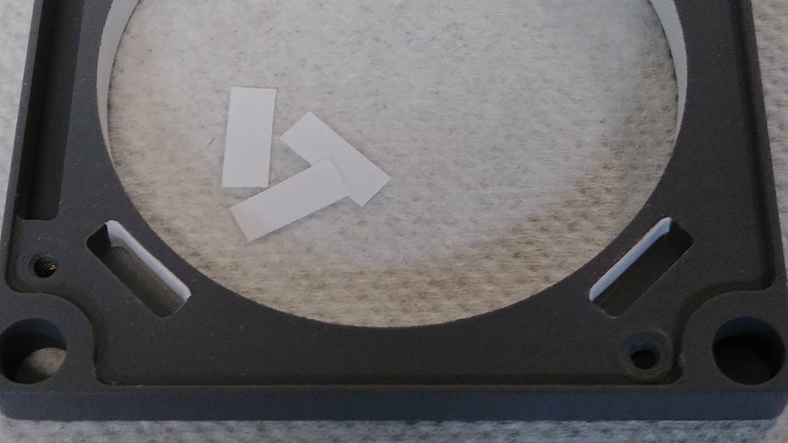
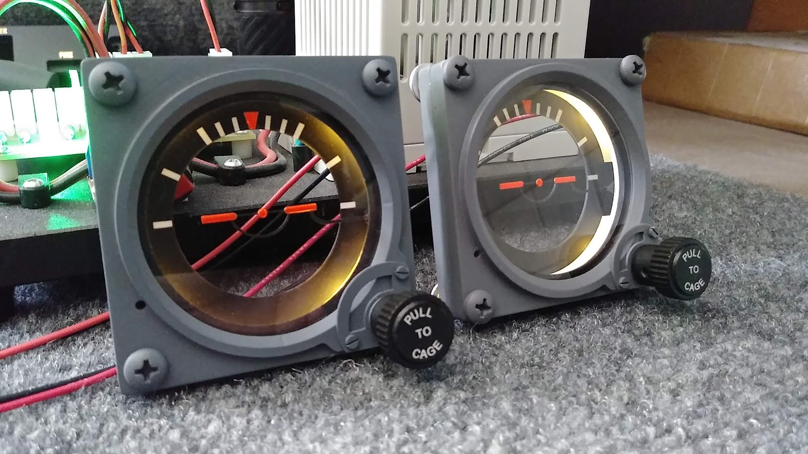
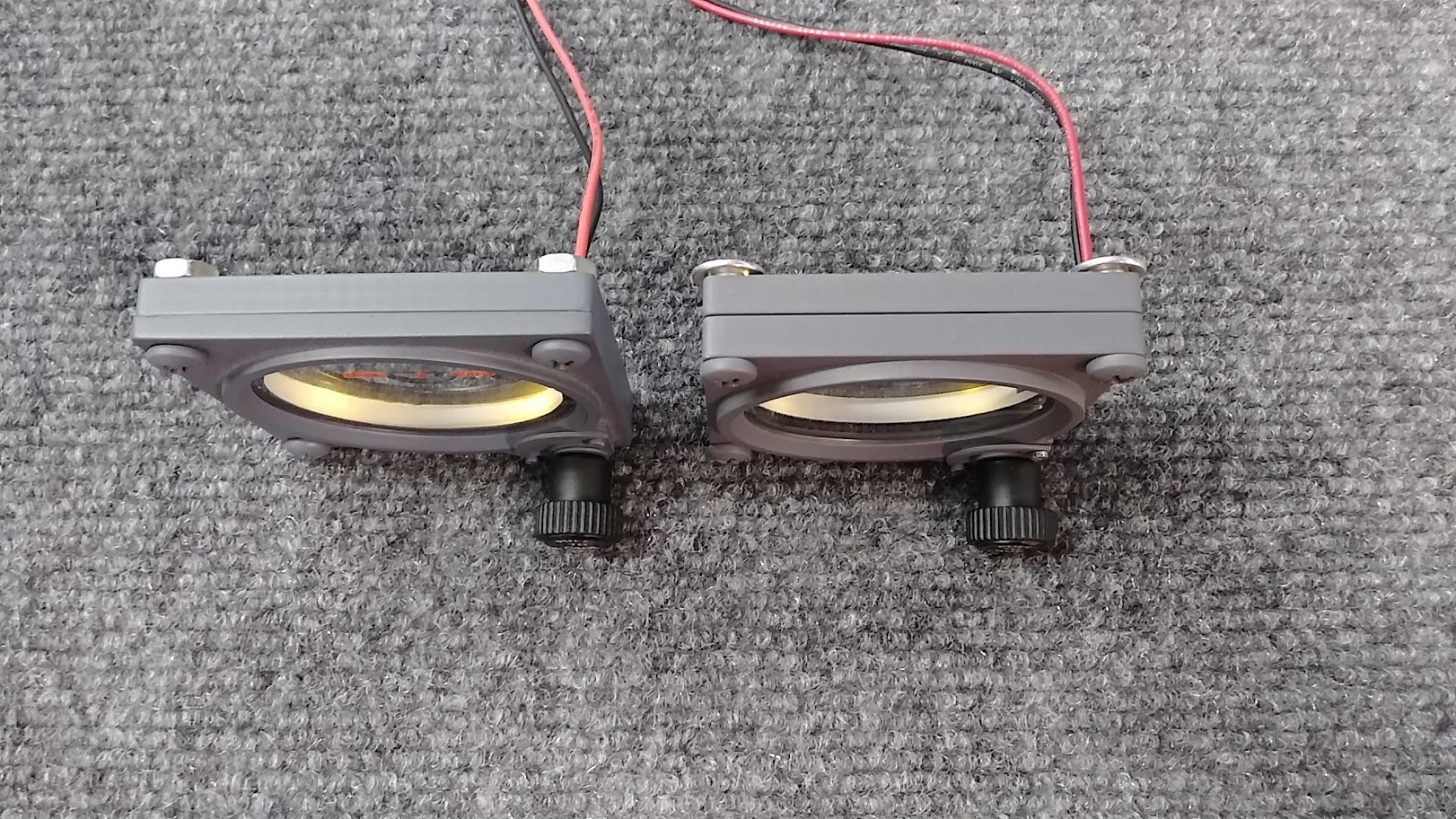
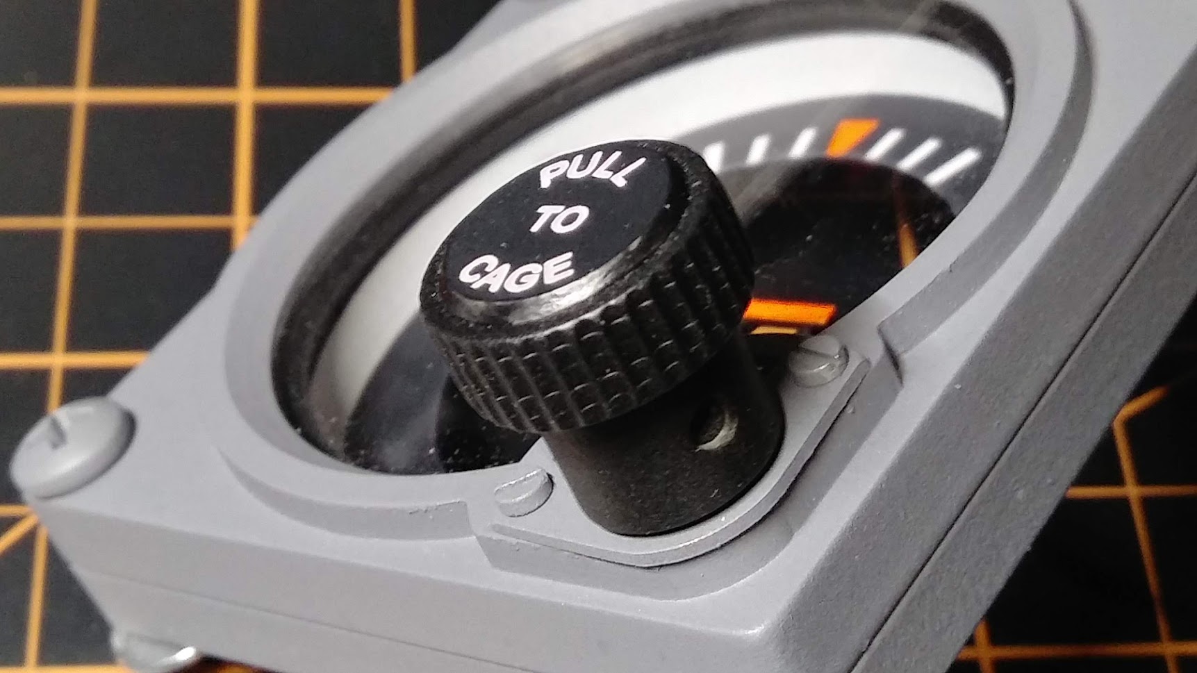
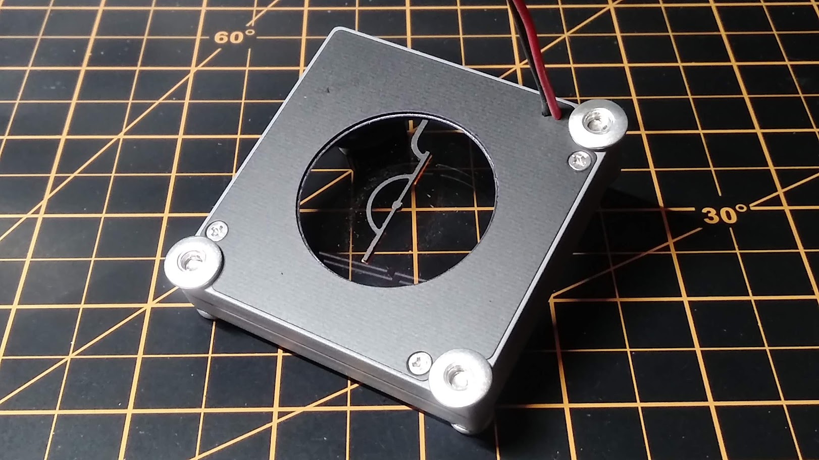
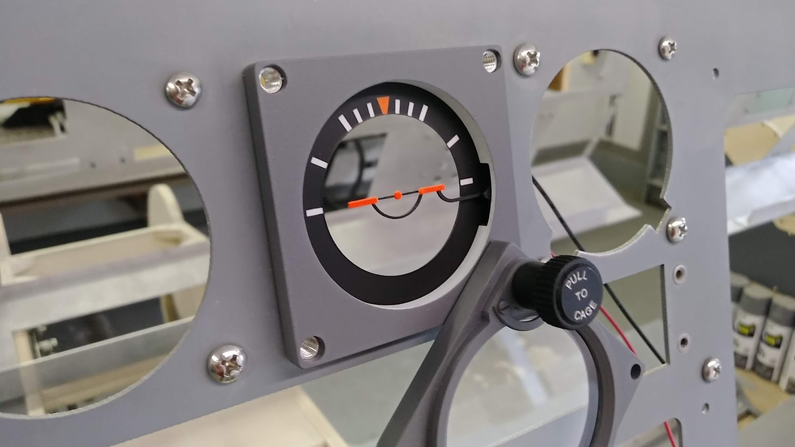
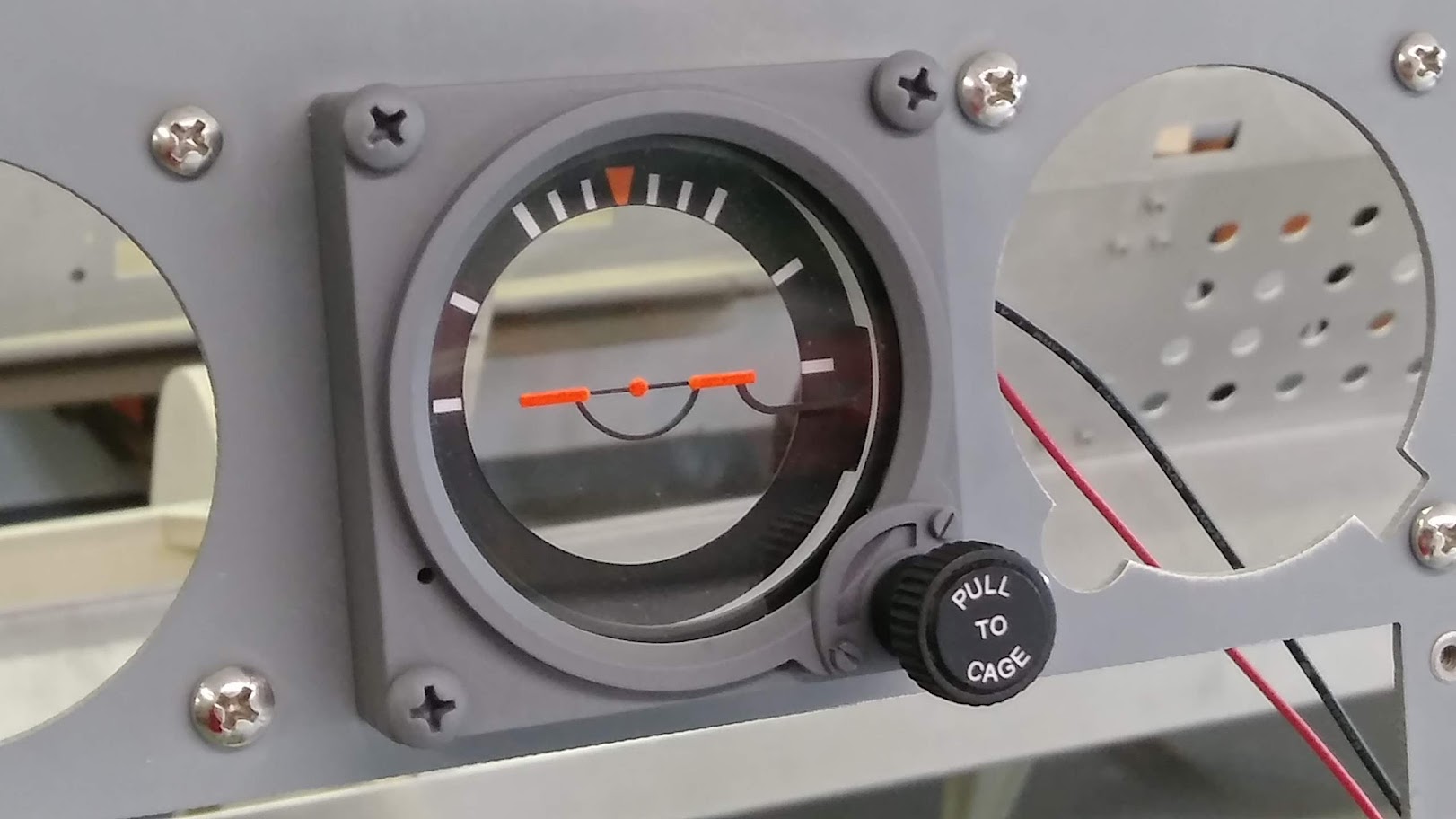
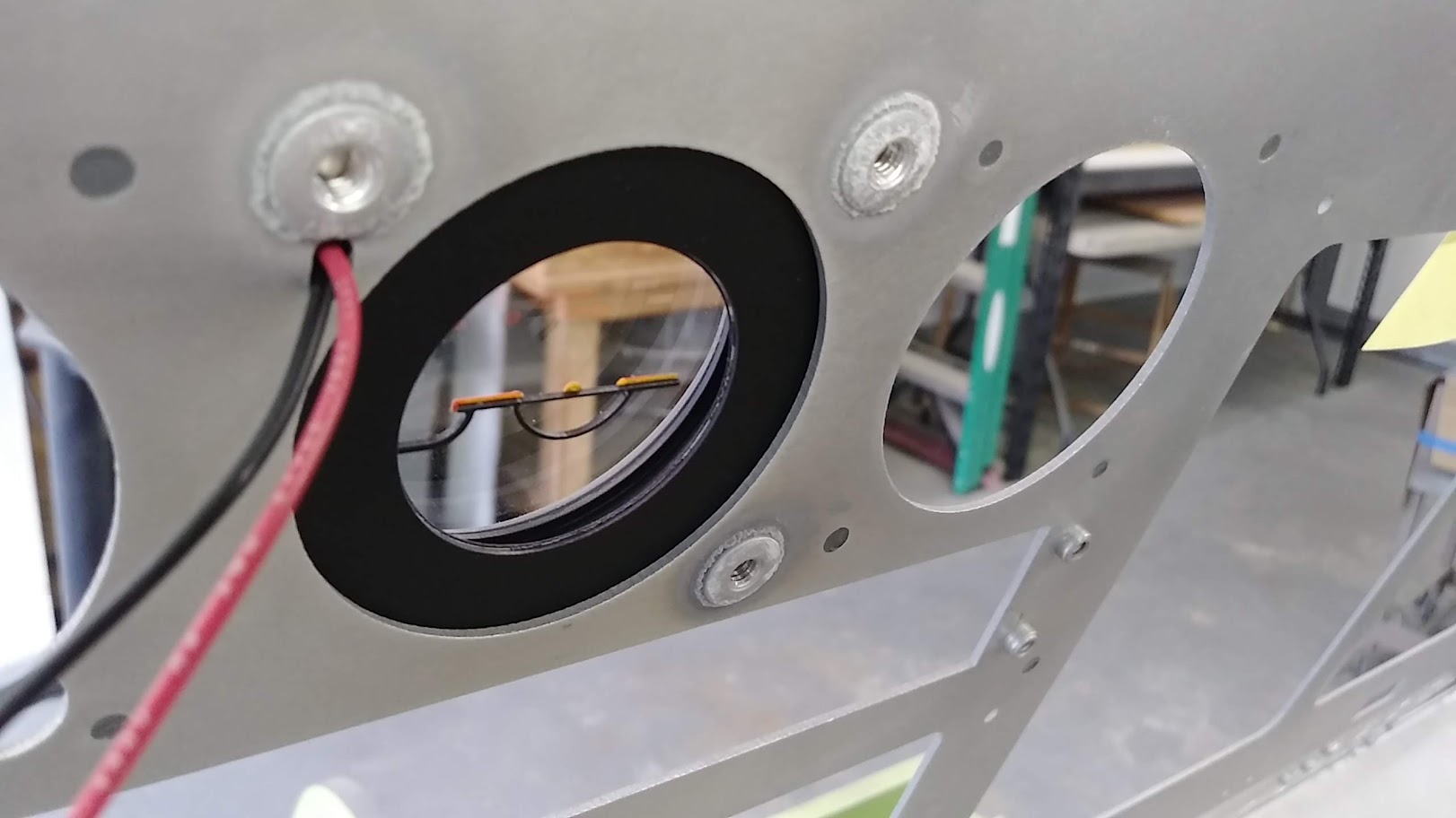
(Original thread started on 08-15-11 by Ron Rollo) Standby Gauge Bezels SPEED, HSI and Altimeter by Project45! It is time to get back to work on the standby gauges. One of the things that I had to master was finding a way to get the rotary encoder built into the side of the altimeter. It turns out that there is not a rotary encoder small enough to just stick in in there while at the same time keeping the gauge to scale. So what we have to do is file, grind, sand and shave the encoder down to size. In other words, put the little guy on a diet! This set of two completed is $75. Or $30 for the airspeed gauge (left) and $45 for the altimeter gauge (right). They are held in place on the MIP with double sided sticky tape for super easy installation: NOTE: The lens are still protected with paper. (Posted by Shane Barnes on 08-16-11) Hey guys, I received the standby gauges from Ron several weeks ago and they are awesome. They really add to the MIP. (Posted by Ron Rollo on 08-17-11) I have taken my MIP out to do some work on the RMUs. While I have the MIP out, it is a chance to show everyone what the back side of the standby gauges look like especially where the encoder is. A side note, in case some of you did not know this, there are at least two standby altimeter designs that you will find in the Lear45. The one I have chosen is the smaller design, which is more challenging to fit the encoder into it. But I personally like the way it looks compared to the other model. Anyway, here is a photo of the back side of the gauges: Another close up showing how everything has to remain low profile because of the LCD screens being right there. You will notice in the previous photo that I am planning to use screw post for the center HSI gauge and the CWP: This way I do not have to pull the MIP back out. I just have to MAKE SURE that the screws are not long enough to touch the LCD screens. And the front view of the two gauges and screw post in place: Over the past two weeks I have been thinking, planning and drawing the HSI center standby gauge as it is high priority because for a few of us, it is the last piece of the puzzle before we can install the MIP once and for all. I had several goals that I had to achieve and I think I have met them all. The first major goal was that I wanted to back light the degree of turn scale and the aircraft symbol. As you know, we have all adopted the LCD screen behind the MIP and these three standby gauges work great because of the work Dave Ault has done. (Thank you Dave!) The LCD screen lights up the gauges, however, I wanted to make as much of the HSI with real parts so that only the "gyro" in Dave's program is seen moving on the LCD screen. Therefor, the scale may not look like it is illuminated compared to the other two gauges if it did not have it's own lighting. The second major thing that I wanted to work into my design is an adjustable aircraft symbol. I wanted to be able to move the plane up and down to slightly adjust it to the pilot's eye point. It is a small detail and something that will hardly ever get touched but I think it is cool! This is a real Lear45 HSI: I wanted to post this up so you guys can see the detail of it and what I am putting into my design. Here is my prototype HSI. I have been working on it for the past four days. The aircraft symbol and knob have not been completed yet: I am using post fasteners to attach the HSI to the MIP: I am using four SMD LED's to light up HSI without the aircraft symbol installed yet. And here is the HSI a day later with the aircraft symbol: (You will note the the A/C symbol is slightly off center. It's a prototype!) This photo shows the A/C symbol adjusted to it's max height: I used .032" double sided copper clad to make the frame work to the A/C symbol. It is super strong, strong enough to stand on it like a spring board believe it or not! Here is is adjusted down: All of the HSI's that I send out will be sealed closed to keep all the parts from falling out. By the way, now I know what it is like to build a watch! I have a little tweaking and tuning to do but with that said, I would say I am 95% there. I will need one more week to complete the knob before I start a production run. Speaking of the knobs, I will include the art work "PULL TO CAGE" on the face of the knobs. NOTE: This is a function that will not be available obviously! If you would like to get on the list, either post here or email me. The price will be $165. (Posted by Dave Ault on 11-10-11) Great work Ron, glad I put the option of having just the gyro in now. Look forward to seeing it with the image behind it. (Posted by Mark Speechley on 11-12-11) I think I'm safe in saying that we all greatly appreciate the effort you put into your designs and construction. You have made our dreams of a cockpit infinitely easier to achieve. A big Thank You. (Posted by Ron Rollo on 11-22-11) Just a real quick weekly update on the HSI production. I am about 50% complete with cutting out 10 sets and 25% complete with the overall process of building them up. Lots of small detail and lots of hand time as you can imagine: The artwork to the face of the knobs, "PULL TO CAGE" came out nice! But please don't pull it when you get it!!! Make sure you brief your guest pilots that at least this part of the knob is only for show: I have four major parts built into this knob. It is not an exact replica of the real one but it is sure gonna be close. If you notice the white ring around the artwork, that is actually a guide line so that I can carve a 45 degree bevel into the cap just like the real knob. I have twelve knobs completed. They turned out better than I could have hoped for when I was trying to figure out how I was going to go about it. Each knob has two pieces made with the CNC, one piece cut on a laser and two pieces that I picked up at the hardware store: Each one already has the set screw installed. You will also notice that I have trimmed the edge of the knob cap by giving it a 45 degree bevel. This bevel only goes half way down the 1/8th inch cap. I used the white laser engraved rings as a guide to make them as close to perfect as I could get them. Just a quick update on the HSI progress. I have ALL the parts cut out for ten sets and I am about 40% complete with building them all up. Next week I should start shipping them out. For those on the list, I will email you when they are ready. I have finally finished the batch of HSI's! Here is a photo of all ten together including a Altimeter and an Airspeed bezel: Seven of the HSI's are accounted for. I still have three that need a home. The HSI's by themselves are $165 each including shipping world wide: If you need the complete set of three, they are $240 including shipping word wide. (In case your not aware, the HSI is back lit and the artificial aircraft can be adjusted up and down.) (Posted by Will Sasse on 01-03-12) Superb work Ron! Looking forward to seeing for real. Does it mount to the panel using double sided sticky tape like the other two gauges? (Posted by Ron Rollo on 01-03-12) Hey Will, not this one. I am using screw post fasteners that have to be put through the three holes on the MIP from the back side and super glued in place to keep them from moving or turning when fasten from the front side. (Only three holes, the fourth would be where the knob is in the bottom right hand corner) So you have to remove the MIP to install the HSI, which is why I was hell bent on completing these so we don't have to pull the MIP back out any time soon. The post and the screws are included with the HSI, so no worries. I have just completed my third batch of HSI bezels. Of this six pack, I have three available. Email me if you would like one: Here is a photo of Dave's gauges behind the bezels! (Posted by Terry Collins on 12-31-12) Ron, that sure is a nice photo of the gauges working with Dave's software! (Original thread started on 08-15-11 by Ron Rollo) Standby Gauge Bezels SPEED, HSI and Altimeter by Project45! It is time to get back to work on the standby gauges. One of the things that I had to master was finding a way to get the rotary encoder built into the side of the altimeter. It turns out that there is not a rotary encoder small enough to just stick in in there while at the same time keeping the gauge to scale. So what we have to do is file, grind, sand and shave the encoder down to size. In other words, put the little guy on a diet! This set of two completed is $75. Or $30 for the airspeed gauge (left) and $45 for the altimeter gauge (right). They are held in place on the MIP with double sided sticky tape for super easy installation: NOTE: The lens are still protected with paper. (Posted by Shane Barnes on 08-16-11) Hey guys, I received the standby gauges from Ron several weeks ago and they are awesome. They really add to the MIP. (Posted by Ron Rollo on 08-17-11) I have taken my MIP out to do some work on the RMUs. While I have the MIP out, it is a chance to show everyone what the back side of the standby gauges look like especially where the encoder is. A side note, in case some of you did not know this, there are at least two standby altimeter designs that you will find in the Lear45. The one I have chosen is the smaller design, which is more challenging to fit the encoder into it. But I personally like the way it looks compared to the other model. Anyway, here is a photo of the back side of the gauges: Another close up showing how everything has to remain low profile because of the LCD screens being right there. You will notice in the previous photo that I am planning to use screw post for the center HSI gauge and the CWP: This way I do not have to pull the MIP back out. I just have to MAKE SURE that the screws are not long enough to touch the LCD screens. And the front view of the two gauges and screw post in place: Over the past two weeks I have been thinking, planning and drawing the HSI center standby gauge as it is high priority because for a few of us, it is the last piece of the puzzle before we can install the MIP once and for all. I had several goals that I had to achieve and I think I have met them all. The first major goal was that I wanted to back light the degree of turn scale and the aircraft symbol. As you know, we have all adopted the LCD screen behind the MIP and these three standby gauges work great because of the work Dave Ault has done. (Thank you Dave!) The LCD screen lights up the gauges, however, I wanted to make as much of the HSI with real parts so that only the "gyro" in Dave's program is seen moving on the LCD screen. Therefor, the scale may not look like it is illuminated compared to the other two gauges if it did not have it's own lighting. The second major thing that I wanted to work into my design is an adjustable aircraft symbol. I wanted to be able to move the plane up and down to slightly adjust it to the pilot's eye point. It is a small detail and something that will hardly ever get touched but I think it is cool! This is a real Lear45 HSI: I wanted to post this up so you guys can see the detail of it and what I am putting into my design. Here is my prototype HSI. I have been working on it for the past four days. The aircraft symbol and knob have not been completed yet: I am using post fasteners to attach the HSI to the MIP: I am using four SMD LED's to light up HSI without the aircraft symbol installed yet. And here is the HSI a day later with the aircraft symbol: (You will note the the A/C symbol is slightly off center. It's a prototype!) This photo shows the A/C symbol adjusted to it's max height: I used .032" double sided copper clad to make the frame work to the A/C symbol. It is super strong, strong enough to stand on it like a spring board believe it or not! Here is is adjusted down: All of the HSI's that I send out will be sealed closed to keep all the parts from falling out. By the way, now I know what it is like to build a watch! I have a little tweaking and tuning to do but with that said, I would say I am 95% there. I will need one more week to complete the knob before I start a production run. Speaking of the knobs, I will include the art work "PULL TO CAGE" on the face of the knobs. NOTE: This is a function that will not be available obviously! If you would like to get on the list, either post here or email me. The price will be $165. (Posted by Dave Ault on 11-10-11) Great work Ron, glad I put the option of having just the gyro in now. Look forward to seeing it with the image behind it. (Posted by Mark Speechley on 11-12-11) I think I'm safe in saying that we all greatly appreciate the effort you put into your designs and construction. You have made our dreams of a cockpit infinitely easier to achieve. A big Thank You. (Posted by Ron Rollo on 11-22-11) Just a real quick weekly update on the HSI production. I am about 50% complete with cutting out 10 sets and 25% complete with the overall process of building them up. Lots of small detail and lots of hand time as you can imagine: The artwork to the face of the knobs, "PULL TO CAGE" came out nice! But please don't pull it when you get it!!! Make sure you brief your guest pilots that at least this part of the knob is only for show: I have four major parts built into this knob. It is not an exact replica of the real one but it is sure gonna be close. If you notice the white ring around the artwork, that is actually a guide line so that I can carve a 45 degree bevel into the cap just like the real knob. I have twelve knobs completed. They turned out better than I could have hoped for when I was trying to figure out how I was going to go about it. Each knob has two pieces made with the CNC, one piece cut on a laser and two pieces that I picked up at the hardware store: Each one already has the set screw installed. You will also notice that I have trimmed the edge of the knob cap by giving it a 45 degree bevel. This bevel only goes half way down the 1/8th inch cap. I used the white laser engraved rings as a guide to make them as close to perfect as I could get them. Just a quick update on the HSI progress. I have ALL the parts cut out for ten sets and I am about 40% complete with building them all up. Next week I should start shipping them out. For those on the list, I will email you when they are ready. I have finally finished the batch of HSI's! Here is a photo of all ten together including a Altimeter and an Airspeed bezel: Seven of the HSI's are accounted for. I still have three that need a home. The HSI's by themselves are $165 each including shipping world wide: If you need the complete set of three, they are $240 including shipping word wide. (In case your not aware, the HSI is back lit and the artificial aircraft can be adjusted up and down.) (Posted by Will Sasse on 01-03-12) Superb work Ron! Looking forward to seeing for real. Does it mount to the panel using double sided sticky tape like the other two gauges? (Posted by Ron Rollo on 01-03-12) Hey Will, not this one. I am using screw post fasteners that have to be put through the three holes on the MIP from the back side and super glued in place to keep them from moving or turning when fasten from the front side. (Only three holes, the fourth would be where the knob is in the bottom right hand corner) So you have to remove the MIP to install the HSI, which is why I was hell bent on completing these so we don't have to pull the MIP back out any time soon. The post and the screws are included with the HSI, so no worries. I have just completed my third batch of HSI bezels. Of this six pack, I have three available. Email me if you would like one: Here is a photo of Dave's gauges behind the bezels! (Posted by Terry Collins on 12-31-12) Ron, that sure is a nice photo of the gauges working with Dave's software! Over the past few weeks I have been working to update the three main standby gauges. Honestly, there is not much to update with the exception of the back lighting in the Attitude Standby gauge. Currently the v1.0 Attitude Standby gauge is designed with four LEDs wired in series and only accepts 12v power. The new v2.0 Attitude Standby gauge will use resistors wired in parallel, will be 5v ready and will also handle voltage as high as 12 volts. More on that as the new Attitude Standby gauge is developed. The other two standby gauges are fairly simple. Starting with the Airspeed Standby gauge, the only change is the scale. The older v1.0 Airspeed bezel was about 5% under sized, barely noticeable. Between then and now, we have obtained documentation, (thanks to DonnyRay) that has enabled me to zero in precisely on the scale of the gauges. Here you can see there are a few ready to go! The Altitude Standby gauge is a little more challenging because of the tiny encoder embedded in the side of the bezel. Remember, NOTHING can fall in behind the MIP because there is an LCD screen sitting right there behind the MIP. To make things more difficult, the encoder has to be shaved in order to fit in the bezel body. See photo. The encode on the left is untouched. The one on the right has the tiny tab shaved off and the threads on the shaft removed. Thankfully the metal is really soft and shaves off easily. Just make sure you wrap the brass shaft with blue painters tape to protect it from you files. The final step is to buff the encoder with a soft sanding block. But the worst part about the Altimeter Standby gauge is the fact that the encoder that I use is now obsolete and I can't find a replacement for it. The part number for the encoder is 318-ENC70120F-10P if you want to see if you can find them somewhere. Put your best search techniques at work to see if you can find a couple. I only have three spares and that's it! What this means is if you would like to upgrade to the new v2.0 Altitude Standby gauge, you will need to use the encoder you already have in your v1.0 Altitude Standby gauge. The good news is the future mechanical gauges will be free to use different hardware. Beside the scale of the Altimeter Standby gauge being corrected, the only other change is the knob is a little taller to better replicate what is found on the real thing. As you know, the three standbys are currently just bezels that are mounted to the face of the MIP with a LCD screen behind the MIP displaying Dave Ault's gauges. A great solution for now! Down the road there are plans to make a set of mechanical standby gauges. The design work is about 50% complete, however, they will not be advanced any further until several other higher priority projects are taken care of first. It is a project that I am really looking forward to with the help of Jason and his incredible software skills! More updates on the Attitude Standby soon! Over the past few weeks I have been working to update the three main standby gauges. Honestly, there is not much to update with the exception of the back lighting in the Attitude Standby gauge. Currently the v1.0 Attitude Standby gauge is designed with four LEDs wired in series and only accepts 12v power. The new v2.0 Attitude Standby gauge will use resistors wired in parallel, will be 5v ready and will also handle voltage as high as 12 volts. More on that as the new Attitude Standby gauge is developed. The other two standby gauges are fairly simple. Starting with the Airspeed Standby gauge, the only change is the scale. The older v1.0 Airspeed bezel was about 5% under sized, barely noticeable. Between then and now, we have obtained documentation, (thanks to DonnyRay) that has enabled me to zero in precisely on the scale of the gauges. Here you can see there are a few ready to go! The Altitude Standby gauge is a little more challenging because of the tiny encoder embedded in the side of the bezel. Remember, NOTHING can fall in behind the MIP because there is an LCD screen sitting right there behind the MIP. To make things more difficult, the encoder has to be shaved in order to fit in the bezel body. See photo. The encode on the left is untouched. The one on the right has the tiny tab shaved off and the threads on the shaft removed. Thankfully the metal is really soft and shaves off easily. Just make sure you wrap the brass shaft with blue painters tape to protect it from you files. The final step is to buff the encoder with a soft sanding block. But the worst part about the Altimeter Standby gauge is the fact that the encoder that I use is now obsolete and I can't find a replacement for it. The part number for the encoder is 318-ENC70120F-10P if you want to see if you can find them somewhere. Put your best search techniques at work to see if you can find a couple. I only have three spares and that's it! What this means is if you would like to upgrade to the new v2.0 Altitude Standby gauge, you will need to use the encoder you already have in your v1.0 Altitude Standby gauge. The good news is the future mechanical gauges will be free to use different hardware. Beside the scale of the Altimeter Standby gauge being corrected, the only other change is the knob is a little taller to better replicate what is found on the real thing. As you know, the three standbys are currently just bezels that are mounted to the face of the MIP with a LCD screen behind the MIP displaying Dave Ault's gauges. A great solution for now! Down the road there are plans to make a set of mechanical standby gauges. The design work is about 50% complete, however, they will not be advanced any further until several other higher priority projects are taken care of first. It is a project that I am really looking forward to with the help of Jason and his incredible software skills! More updates on the Attitude Standby soon! Hey guys, I just completed what I call the v1.1. Standby Attitude Update! This is part one of two parts when it comes to the updated Attitude gauges I am working on. First, I had to address the old v1.0 Attitude gauges that were designed in series with no resistors. They work fine with 12 volt power but do not work with the now preferred 5 volt power that we are planning for. The new v2.0 Attitude gauges along with the v1.1 Attitude gauge updates are all designed using parallel wiring and also include a 430 ohm resistor along side each of the four LEDs. This is standard in all my panels and the ones Eric made back in the day. The other update on the Attitude gauge is the use of high resolution full color 3 mil vinyl decals! Not only is the quality better than what I could do manually, this method saves tons of time. Thanks to Will and Roel for the tips in this department! Here is a photo of the old clad (left) and new clad (right) side by side. For you guys doing this update, there is only a few things that you will need to do on your own. First, take it apart. The other thing that you will have to do is carve out the LED pockets a little on each end. In this photo, you can see the four pockets after I have carved the ends out with an Exacto knife. A closer look at one of the pockets carved out. Right click on the photo and open in a new tab to get a super close look. And that's it! Put is all back together and the modification is complete. What you have now is a Standby Attitude gauge that is now 5 volt compatible. And if you want to stick with 12 volts, you can. Here is the old v1.0 Standby Attitude gauge updated to v1.1. I have said it in several other threads and it is worth saying again, this method of back lighting is not only flexible, but it is safer for the LEDs. There is almost no chance that you can blow your LEDs in this gauge or any other panels when wiring in parallel as long as you use 12 volts or less. Always plan you designs in parallel, never in series. Here are six v1.1 Standby Attitude Updates ready to go! Trying to take photos of panels and gauges lit up is hit and miss. The photos never do justice. I am planning to play around with adding paper filters and or white paint in the LED pockets to see if I can tame the hot spots a little more. I can certainly improve this and will keep you posted on that. As I mentioned at the beginning of this post, this is part one of two. The second part is building the new v2.0 Standby Attitude gauge. It will look exactly like what you see above but the scale is about 2% larger. Hardly noticeable but while we are in the mode to rework EVERYTHING, the Attitude gauge will also get a bit of a make over. It will of course include the changes mentioned above. Standby for the v2.0 Standby Attitude! Hey guys, I just completed what I call the v1.1. Standby Attitude Update! This is part one of two parts when it comes to the updated Attitude gauges I am working on. First, I had to address the old v1.0 Attitude gauges that were designed in series with no resistors. They work fine with 12 volt power but do not work with the now preferred 5 volt power that we are planning for. The new v2.0 Attitude gauges along with the v1.1 Attitude gauge updates are all designed using parallel wiring and also include a 430 ohm resistor along side each of the four LEDs. This is standard in all my panels and the ones Eric made back in the day. The other update on the Attitude gauge is the use of high resolution full color 3 mil vinyl decals! Not only is the quality better than what I could do manually, this method saves tons of time. Thanks to Will and Roel for the tips in this department! Here is a photo of the old clad (left) and new clad (right) side by side. For you guys doing this update, there is only a few things that you will need to do on your own. First, take it apart. The other thing that you will have to do is carve out the LED pockets a little on each end. In this photo, you can see the four pockets after I have carved the ends out with an Exacto knife. A closer look at one of the pockets carved out. Right click on the photo and open in a new tab to get a super close look. And that's it! Put is all back together and the modification is complete. What you have now is a Standby Attitude gauge that is now 5 volt compatible. And if you want to stick with 12 volts, you can. Here is the old v1.0 Standby Attitude gauge updated to v1.1. I have said it in several other threads and it is worth saying again, this method of back lighting is not only flexible, but it is safer for the LEDs. There is almost no chance that you can blow your LEDs in this gauge or any other panels when wiring in parallel as long as you use 12 volts or less. Always plan you designs in parallel, never in series. Here are six v1.1 Standby Attitude Updates ready to go! Trying to take photos of panels and gauges lit up is hit and miss. The photos never do justice. I am planning to play around with adding paper filters and or white paint in the LED pockets to see if I can tame the hot spots a little more. I can certainly improve this and will keep you posted on that. As I mentioned at the beginning of this post, this is part one of two. The second part is building the new v2.0 Standby Attitude gauge. It will look exactly like what you see above but the scale is about 2% larger. Hardly noticeable but while we are in the mode to rework EVERYTHING, the Attitude gauge will also get a bit of a make over. It will of course include the changes mentioned above. Standby for the v2.0 Standby Attitude! Hey guys, Quick update on the new v2.0 Attitude Gauge bezels. They are about 70% complete and should be finished by the end of next week. Again, they will look and operate just like the the v1.1 updated version with the exception of the scale will be closer to the real thing. There are a few other minor changes in the way they are built and held together. As an example, I am using 2-56 screws and brass inserts to hold the rear clad in place. (Not really needed once the main corner screws are in place but a nice update in the design none the less.) In the photo below you will notice that there are only three brass inserts and that is because there is no room in the bottom right corner due to the knob shaft if you are looking at the bezel installed on the MIP. I am also using a plastic light shade ring rather than the paper laser cut ring. This was needed because the thickness of the new top front cover is now .33" thick rather than .23" thick found in the earlier versions. The thicker ring is needed to hold the clear lens snug in place. Here is a quick photo of the backer part of the Attitude bezel attached to the MIP with the clad also snapped in place to give you an idea of what is "under the hood" so to speak. The backer part is where the light chamber is found and the channels for the moving parts that allow us to adjust the airplane symbol up and down slightly. The Vinyl artwork sticker, LEDs and resistors still need to be installed. This photos shows how everything stacks on top of each other. This version as I mentioned earlier is a little thicker and closer to 100% scale. It is easy to see the many layers within the bezel when it is not painted. It's important to show photos like this in case anyone wants to build their own bezels in the future! The new Attitude bezels will be completed in a week or so but what I am excited about is finding the time to make the mechanical gauges in the future. The work being done today is the foundation of the mechanical gauges tomorrow. With that said, the front bezels represent only about 25% of the mechanical gauges so there is still a ton of work to be done. One more update coming soon to complete the new Attitude Gauge bezels! Hey guys, Quick update on the new v2.0 Attitude Gauge bezels. They are about 70% complete and should be finished by the end of next week. Again, they will look and operate just like the the v1.1 updated version with the exception of the scale will be closer to the real thing. There are a few other minor changes in the way they are built and held together. As an example, I am using 2-56 screws and brass inserts to hold the rear clad in place. (Not really needed once the main corner screws are in place but a nice update in the design none the less.) In the photo below you will notice that there are only three brass inserts and that is because there is no room in the bottom right corner due to the knob shaft if you are looking at the bezel installed on the MIP. I am also using a plastic light shade ring rather than the paper laser cut ring. This was needed because the thickness of the new top front cover is now .33" thick rather than .23" thick found in the earlier versions. The thicker ring is needed to hold the clear lens snug in place. Here is a quick photo of the backer part of the Attitude bezel attached to the MIP with the clad also snapped in place to give you an idea of what is "under the hood" so to speak. The backer part is where the light chamber is found and the channels for the moving parts that allow us to adjust the airplane symbol up and down slightly. The Vinyl artwork sticker, LEDs and resistors still need to be installed. This photos shows how everything stacks on top of each other. This version as I mentioned earlier is a little thicker and closer to 100% scale. It is easy to see the many layers within the bezel when it is not painted. It's important to show photos like this in case anyone wants to build their own bezels in the future! The new Attitude bezels will be completed in a week or so but what I am excited about is finding the time to make the mechanical gauges in the future. The work being done today is the foundation of the mechanical gauges tomorrow. With that said, the front bezels represent only about 25% of the mechanical gauges so there is still a ton of work to be done. One more update coming soon to complete the new Attitude Gauge bezels! Hey guys, The updated v2.0 Attitude bezels are finally complete! I only made a run of four this time because most of us already have the earlier version and have elected to just do the v1.1 update fix to make them 5v capable. In any case, because the Attitude bezels are packed full of small details compared to other panels and parts, I want to take a few minutes to document some of the finer points in case anyone wants to make their own. As always, the dxf, G code and other related files will be made available and if you can't find them just ask for them and I will forward them to you. To start with, this photo pretty much shows everything cut, painted, partially assembled and ready for final assembly. You can right click on any of these photos to zoom in on any of the parts. In all, there are over 50 individual parts in just one Attitude bezel! The mechanical gauges later down the road will be a blast because they will have at least triple the parts! This photo shows the internal moving part with the artificial plane already mounted to it along with the threaded knob shaft. You can see one is sitting in the Attitude backer ready to be shifted up or down. I used Polly material (Starboard) which is a plastic to make the main moving part because it is flexible and at the same time strong. The knob is held in place with a set screw and even if you turn the knob as hard as you can, the knob will slip well before there is a chance that the moving part fails. (But please don't try to break it!) To address the hot spots in the light ring, I used four tiny pieces of paper in each of the SMD pockets. I could have used a heavier paper and possibly got away with either one or two pieces, but either way, I just kept adding paper until I was happy with the light spread. As you can see from the photo above, the paper is only mounted to the side of the SMD pocket that is facing the light ring. The idea is to reduce the light in the hot spot while at the same time, allowing the light to spread into the rest of the light chamber. The results are pretty impressive. The photo below is of a v1.1 Attitude bezel on the left without the paper hot spot treatment and the new v2.0 Attitude bezel on the right. As you can see, the light spread is much better. While we are comparing old vs new, let me point out the differences. First, the new v2.0 is slightly smaller than the v1.1. The mounting holes are in exactly the same locations but you can see that the new bezel has the screws hanging off the edges. This is how the real Attitude bezel is designed. The other thing that you might notice is the new Attitude bezel is thicker to better match what the real Attitude gauge is. These differences are hardly noticeable and trivial but none the less, in an effort to make available the best rendition of a Lear45 sim as possible, these changes were necessary. I also had to redesign the knob so that it is closer to scale. The 1.1 knob is also a little over sized. While I was at it, I tightened up the knurls (vertical ribs going around the knob). I learned a couple tricks over the past year or so that enables me to cut the knobs knurls a little tighter. It was not totally necessary to add 2-56 screws and brass inserts to hold the clad plate in place, but I added them anyway. I little more professional look. Just to keep the bezel together, I have some aluminum post installed and holding everything together. Proper installation requires that the aluminum post be installed on the MIP. Here is a photo illustrating the aluminum post installed on the MIP and the backer part of the Attitude bezel slipped onto those post. As you can see, until the three 8-32 screws are installed, the front plate of the Attitude bezel is subject to "dangleation". Once the three screws are in place, the Attitude bezel is properly installed! The installation is solid and ready for Dave Ault's software to be displayed on the LCD screen that will be mounted behind the bezels! A quick look at the back side of the Attitude bezel while mounted to the MIP. As a reminder, for you new fellas coming along, the area behind the standby bezels has to be as flat and unobscured as possible to make room for the LCD screen that will be mounted directly behind the MIP. I think that pretty much covers this last update on the v2.0 standby bezels. They are now properly scaled and the Attitude bezels are able to accept both 5v or 12v power! If you have any questions or need any clarification on anything, please ask! The new v2.0 Attitude bezel along with the other Standby bezels are listed in the HANGAR PRODUCTS page. Hey guys, The updated v2.0 Attitude bezels are finally complete! I only made a run of four this time because most of us already have the earlier version and have elected to just do the v1.1 update fix to make them 5v capable. In any case, because the Attitude bezels are packed full of small details compared to other panels and parts, I want to take a few minutes to document some of the finer points in case anyone wants to make their own. As always, the dxf, G code and other related files will be made available and if you can't find them just ask for them and I will forward them to you. To start with, this photo pretty much shows everything cut, painted, partially assembled and ready for final assembly. You can right click on any of these photos to zoom in on any of the parts. In all, there are over 50 individual parts in just one Attitude bezel! The mechanical gauges later down the road will be a blast because they will have at least triple the parts! This photo shows the internal moving part with the artificial plane already mounted to it along with the threaded knob shaft. You can see one is sitting in the Attitude backer ready to be shifted up or down. I used Polly material (Starboard) which is a plastic to make the main moving part because it is flexible and at the same time strong. The knob is held in place with a set screw and even if you turn the knob as hard as you can, the knob will slip well before there is a chance that the moving part fails. (But please don't try to break it!) To address the hot spots in the light ring, I used four tiny pieces of paper in each of the SMD pockets. I could have used a heavier paper and possibly got away with either one or two pieces, but either way, I just kept adding paper until I was happy with the light spread. As you can see from the photo above, the paper is only mounted to the side of the SMD pocket that is facing the light ring. The idea is to reduce the light in the hot spot while at the same time, allowing the light to spread into the rest of the light chamber. The results are pretty impressive. The photo below is of a v1.1 Attitude bezel on the left without the paper hot spot treatment and the new v2.0 Attitude bezel on the right. As you can see, the light spread is much better. While we are comparing old vs new, let me point out the differences. First, the new v2.0 is slightly smaller than the v1.1. The mounting holes are in exactly the same locations but you can see that the new bezel has the screws hanging off the edges. This is how the real Attitude bezel is designed. The other thing that you might notice is the new Attitude bezel is thicker to better match what the real Attitude gauge is. These differences are hardly noticeable and trivial but none the less, in an effort to make available the best rendition of a Lear45 sim as possible, these changes were necessary. I also had to redesign the knob so that it is closer to scale. The 1.1 knob is also a little over sized. While I was at it, I tightened up the knurls (vertical ribs going around the knob). I learned a couple tricks over the past year or so that enables me to cut the knobs knurls a little tighter. It was not totally necessary to add 2-56 screws and brass inserts to hold the clad plate in place, but I added them anyway. I little more professional look. Just to keep the bezel together, I have some aluminum post installed and holding everything together. Proper installation requires that the aluminum post be installed on the MIP. Here is a photo illustrating the aluminum post installed on the MIP and the backer part of the Attitude bezel slipped onto those post. As you can see, until the three 8-32 screws are installed, the front plate of the Attitude bezel is subject to "dangleation". Once the three screws are in place, the Attitude bezel is properly installed! The installation is solid and ready for Dave Ault's software to be displayed on the LCD screen that will be mounted behind the bezels! A quick look at the back side of the Attitude bezel while mounted to the MIP. As a reminder, for you new fellas coming along, the area behind the standby bezels has to be as flat and unobscured as possible to make room for the LCD screen that will be mounted directly behind the MIP. I think that pretty much covers this last update on the v2.0 standby bezels. They are now properly scaled and the Attitude bezels are able to accept both 5v or 12v power! If you have any questions or need any clarification on anything, please ask! The new v2.0 Attitude bezel along with the other Standby bezels are listed in the HANGAR PRODUCTS page. Standby Gauge Bezels Discussion
![]()

















































2017-10-10


