


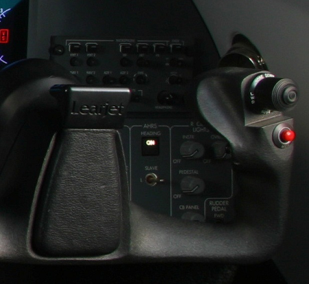
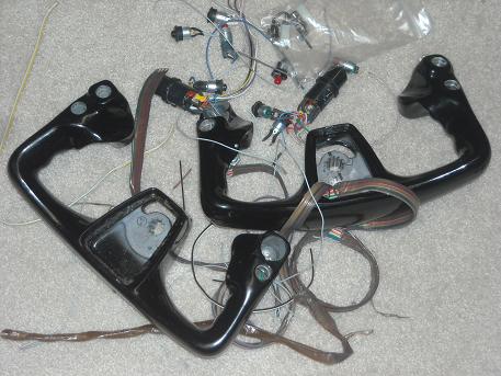
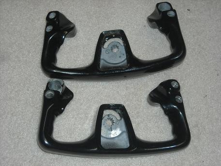
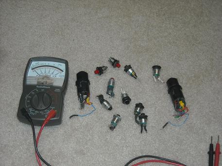
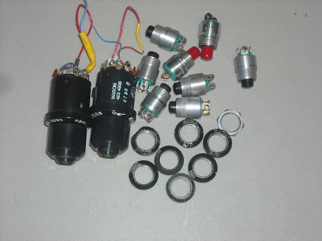
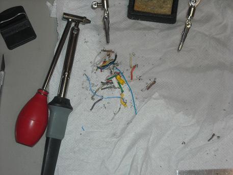
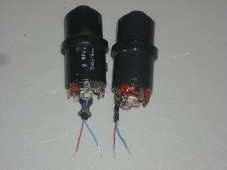
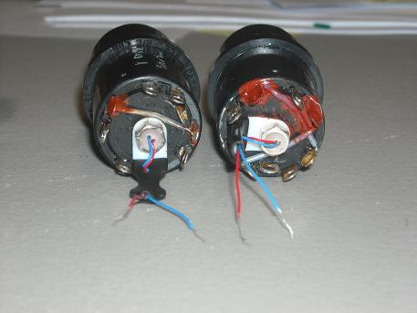
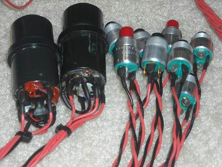
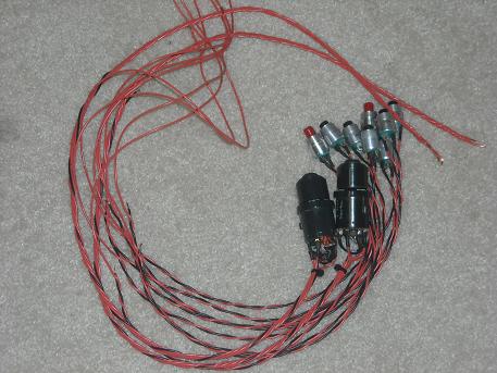
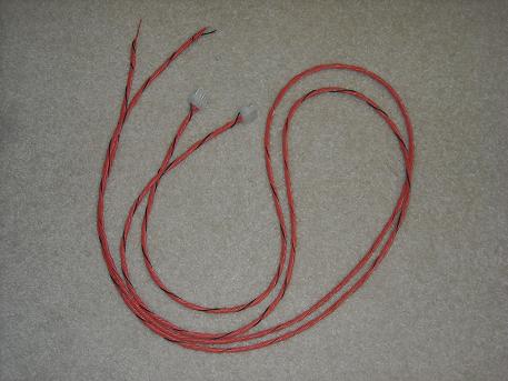
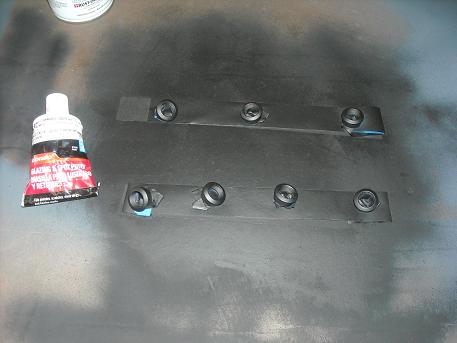
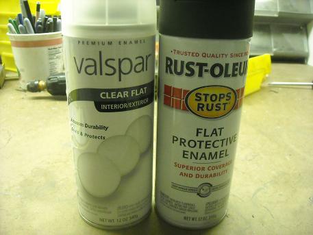
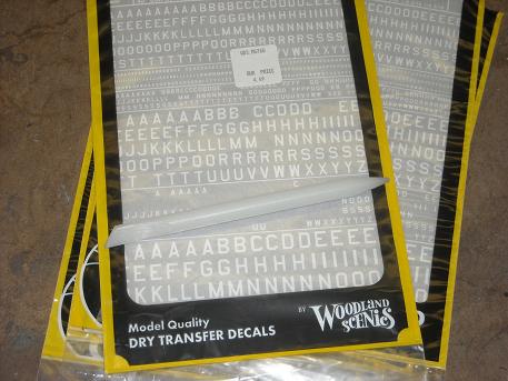
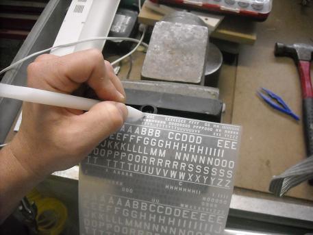
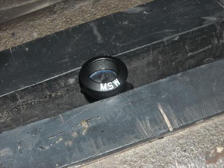
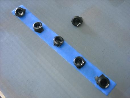
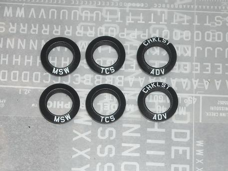
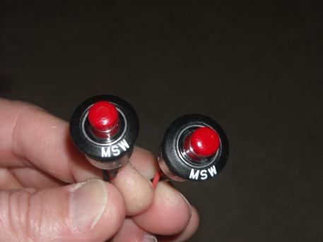
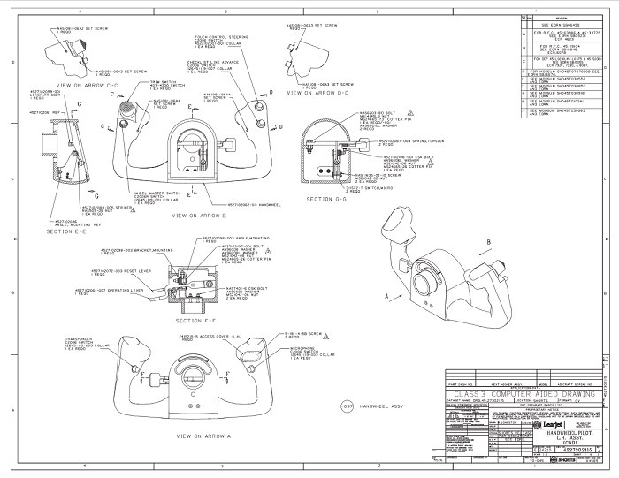
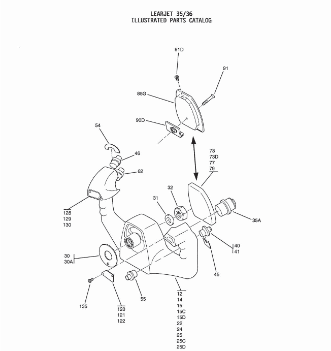
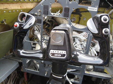
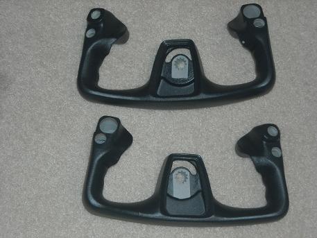
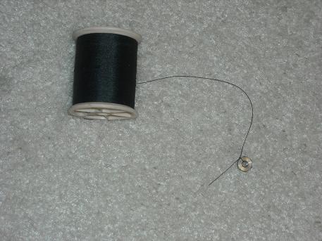
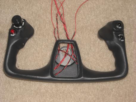
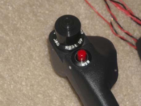
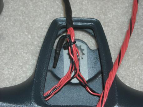
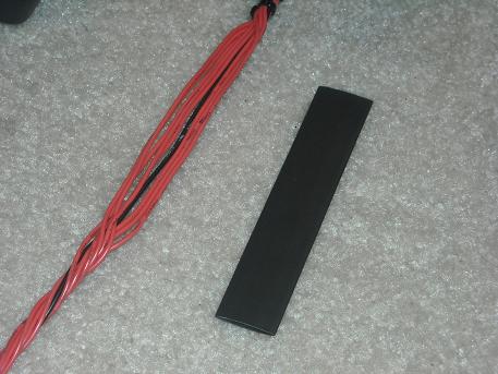
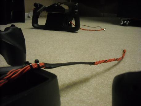
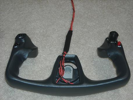
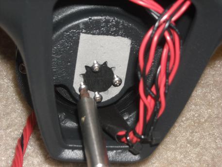
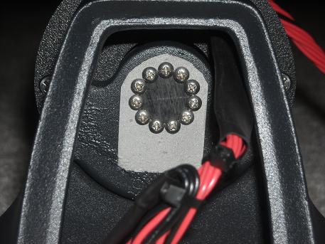
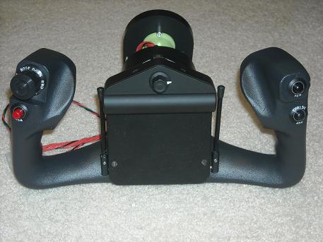
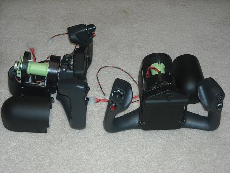
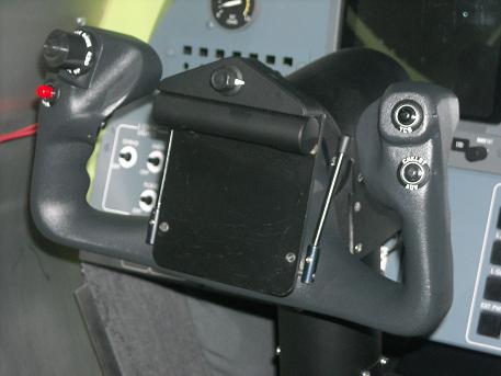
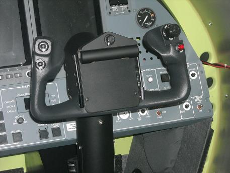
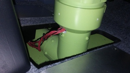
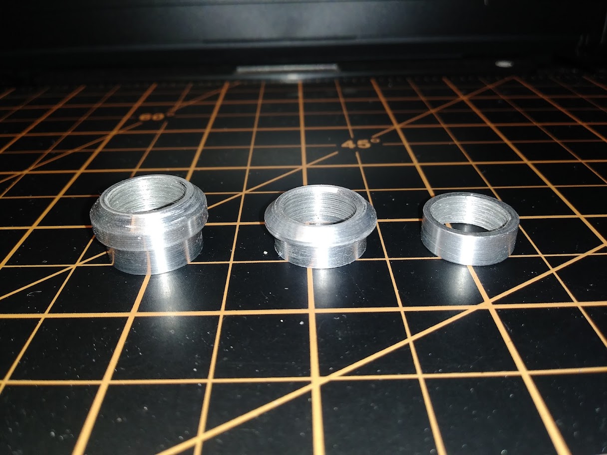
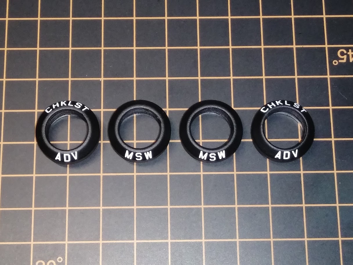
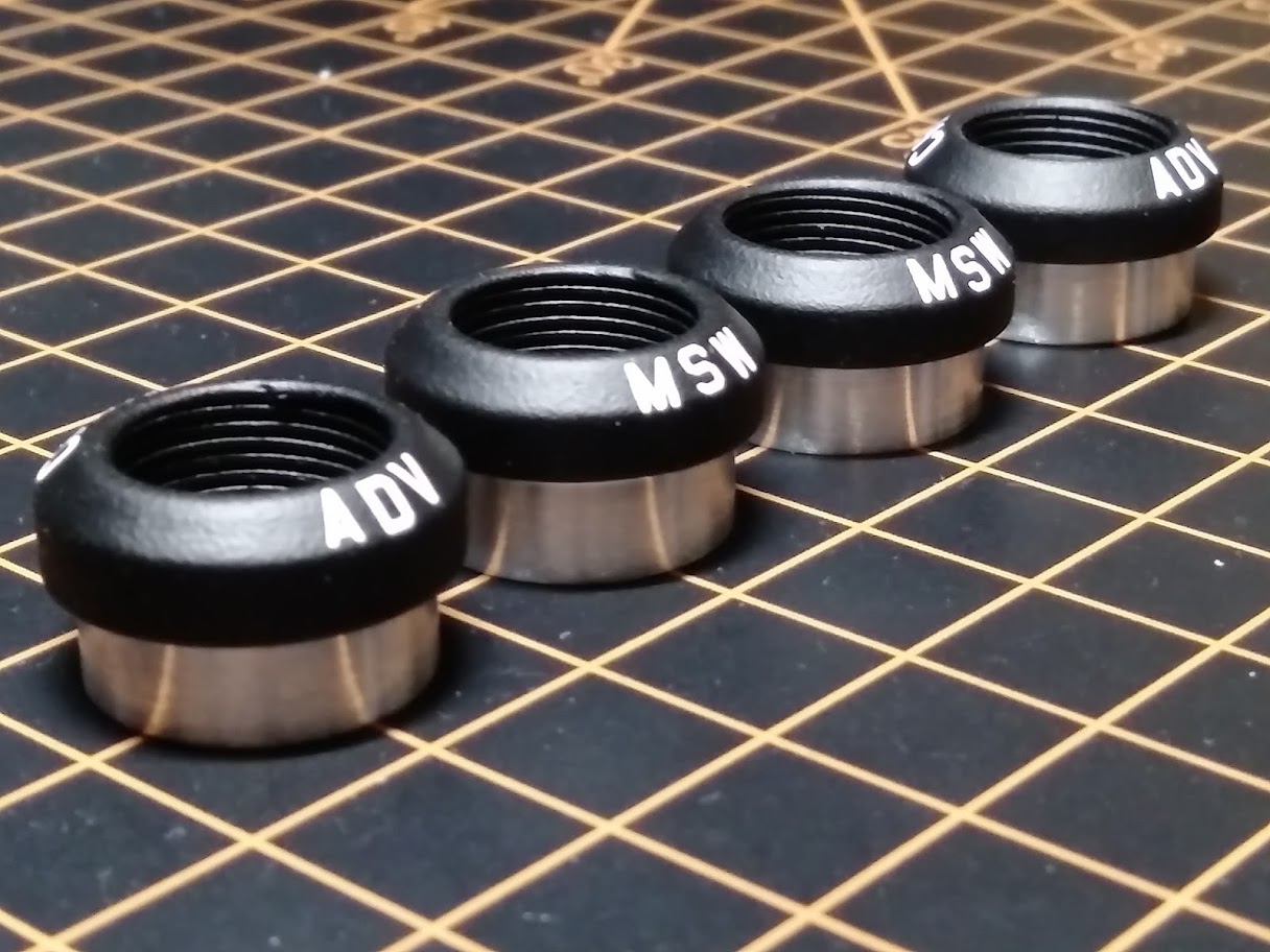
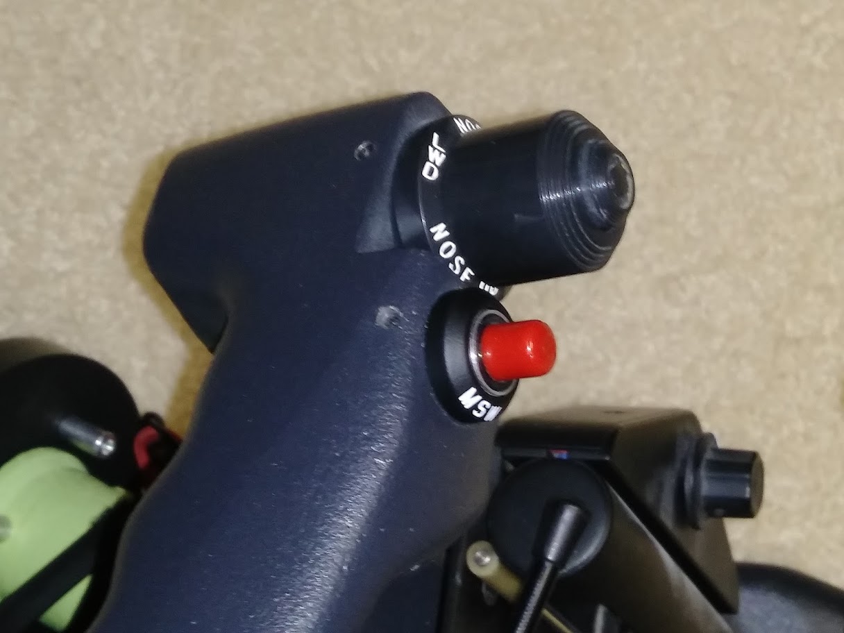
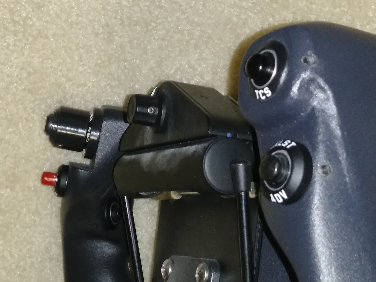
(Original thread started on 04-23-13 by Ron Rollo) Photo of a real Lear45 copilot yoke without a chartholder: I was looking to see what it would take to wire up the pitch trim switches on the yokes. The more I looked at the tangle of wires coming out of the yokes, the more I could clearly see that the best thing to do is to start from scratch. Part 1: My Lear35 yokes each have 16 wires coming out of the backside. But there are only 4 momentary switches and one four way directional hat switch with a center push button. (The center momentary push button on the hat switch is a safety feature so that you don't accidentally hit the trim switch. You have to hold the center button and select the direction of the trim switch simultaneously. You may know this but for the sake of learning bare with me.) So what this means is that each yoke only has eight inputs. And if you know anything about the FDS cards, they work in groups of eight with a single ground! This means that instead of 16 wires with every color in the rainbow coming out of the backside of a yoke, we will only have eight red function wires and one black line for the ground. Further more, I plan to have a quick disconnected in the column and finally a wiring harness that will make its way all the way to the FDS card. If your wondering about duplicate buttons, because as you know, each yoke is duplicated, the FDS card takes care of this also. Just wire everything up to the FDS card and assign each function. You can assign the same function to multiple switches using the InterfaceIT software. I also decided to go a step further with my yokes. I figured that while I have all the wires out of the yokes, what better time to have them sand blasted and powder coated. Tomorrow I will be dropping them off at a local powder coating shop. I'll let you know what to expect with the cost. So lets get started! This is a photo of my two yokes with the wires just about pulled out of them: Here are both yokes cleaned out (with the exception of those few wires in the horns) ready to be sand blasted and powder coated: (I also removed the set screws.) The next thing to do is inventory what you have and check to make sure everything is in working order with a meter. The momentary switches are mostly double pole. We only need single pole. The wiring for the hat switch looks like a mess but it is fairly easy to figure out: (Posted by Shane Barnes on 04-23-13) Already been down this road and adding a quick disconnect in the yoke or in the column is the only way to go! FDS boards make it really simple too. I added a couple inches of extra wiring where it would be easy to pull each switch out a few inches away from the yoke in case a switch needed to be replaced later due to failure etc. Just a little preventive maintenance now should make it a lot easier later to replace a switch. Murphy's law sooner or later it will fail. Looking forward to seeing those yokes finished and hanging in place! (Posted by Ron Rollo on 04-24-13) Part 2: I dropped off the yokes at the powder coating shop today and found out it is going to cost $75 per yoke. So $150 plus tax and seven days. I think that is a fair price. However, the wires I was planning on leaving inside the yokes had to come out because they will melt in the oven which will be set at 400 degrees. That's okay, I know an easy way to thread the wires through the horns. To start with, I used a desoldering iron to remove the remaining wires and solder: If you don't have a desoldering iron, I highly recommend it. The suction is the key to this process: The hat switches clean up nicely. The one thing to be very, VERY careful about is the thin red and blue wires coming out of the center of the back side. Be careful not to break these lines otherwise you will loose the center push feature. These switches are rare and very hard to come by so BE CAREFUL: In this photo you can see a couple of jumper lines running from ground terminal to ground terminal. This will save a few wires. Another point to keep in mind is that the center of this switch rocks depending on which direction you select and the thin red and blue wires need some wiggle room. The manufacture has some kind of a wire holder mounted to the center point to help relieve any stress on the thin red and blue wires at the point where they emerge from the switch. Keep this fact in mind: Here are all of my switches wired and protected with shrink wrap: As you can see, I am using only two colors for the wires. The red lines are the input lines and the black lines are the common ground lines. Once I get the yokes back, I will tie all of the grounds together inside the yokes: While I am waiting for the yokes to come back, I will work on the wiring harnesses and the push button bezels. Posted by Mike Badger on 04-25-13) Hey Ron, do you know where I can buy new buttons for the red and black ones, a couple of my red ones are dull and if I am going to get the yoke looking all pretty I might as well get the new buttons to match. You had me worried about my little red/blue wires all day I couldn't wait to get home and make sure they were there, WHEW, they are! Additionally, anyone know of a good source for replacing those push in hole caps? One of mine is pretty worn and the other one still looks new and shiny. On my yokes I have one unused hole on the pilots yoke and two on the copilots all three were capped with these round covers that had tabs on the backside that when pushed unto the hole they held it in place. (Posted by Ron Rollo on 04-25-13) Hey Mike, unfortunately all the switches in the yokes are very hard to come by. And even when you do find them they are expensive, especially the hat switch. Shane has been looking for yoke switches for over two years with not much luck. When we find them, we will report in this thread! Part 3: A few days ago, I wired up my wiring harnesses. They are pretty much straight forward. Each one has eight signal lines and one ground line: The big update to this thread is the refurbishing of the switch bezels. The original switch bezels were stamped with Lear35 or older switch legends which most of them are obsolete in our Lear45 sims. So I decided to start from scratch on all of them. First I filled in the old lettering with glazing putty. Then I painted them. I had to do this about three times until there was no trace of the old legends: By the way, I used flat black and later I used a flat clear to protect my new lettering: I used dry transfers by Woodland Scenics for my lettering. This will work and last as long as you use the protective clear coat and handle them with care: Use a bench vice to hold the switch bezels otherwise this would be impossible: This is the MSW switch bezel: (The font is a tad off but the lettering is so small that you hardly notice) Next spray the flat clear coat on them to seal in the lettering: Here they are ready to be installed on the switches. Notice that I am missing the MIC switch bezels? This is because I am one bezel short. The other one not pictured has a flat side to it. As you may know, the MIC switches are mounted on the back side of the yokes and can not be seen unless your really looking for them. So in other words, if you have an eye sore or two, move them to the MIC switch spots: Here are the two MSW switch bezels mounted on the switch housings. Now if I only had the yokes back from the powder coating shop: I used MG740 45 degree USA GOTHIC WHITE. But this font is not correct. There is another one available by Woodland Scenics that is a lot closer but it has never been in stock when I go to the hobby stores. As for a list of the legends on the yokes: MSW TCS CHKLST ADV MIC The hat switch has legends on it as well but we do not need to fool with that. (Original thread started on 04-23-13 by Ron Rollo) Photo of a real Lear45 copilot yoke without a chartholder: I was looking to see what it would take to wire up the pitch trim switches on the yokes. The more I looked at the tangle of wires coming out of the yokes, the more I could clearly see that the best thing to do is to start from scratch. Part 1: My Lear35 yokes each have 16 wires coming out of the backside. But there are only 4 momentary switches and one four way directional hat switch with a center push button. (The center momentary push button on the hat switch is a safety feature so that you don't accidentally hit the trim switch. You have to hold the center button and select the direction of the trim switch simultaneously. You may know this but for the sake of learning bare with me.) So what this means is that each yoke only has eight inputs. And if you know anything about the FDS cards, they work in groups of eight with a single ground! This means that instead of 16 wires with every color in the rainbow coming out of the backside of a yoke, we will only have eight red function wires and one black line for the ground. Further more, I plan to have a quick disconnected in the column and finally a wiring harness that will make its way all the way to the FDS card. If your wondering about duplicate buttons, because as you know, each yoke is duplicated, the FDS card takes care of this also. Just wire everything up to the FDS card and assign each function. You can assign the same function to multiple switches using the InterfaceIT software. I also decided to go a step further with my yokes. I figured that while I have all the wires out of the yokes, what better time to have them sand blasted and powder coated. Tomorrow I will be dropping them off at a local powder coating shop. I'll let you know what to expect with the cost. So lets get started! This is a photo of my two yokes with the wires just about pulled out of them: Here are both yokes cleaned out (with the exception of those few wires in the horns) ready to be sand blasted and powder coated: (I also removed the set screws.) The next thing to do is inventory what you have and check to make sure everything is in working order with a meter. The momentary switches are mostly double pole. We only need single pole. The wiring for the hat switch looks like a mess but it is fairly easy to figure out: (Posted by Shane Barnes on 04-23-13) Already been down this road and adding a quick disconnect in the yoke or in the column is the only way to go! FDS boards make it really simple too. I added a couple inches of extra wiring where it would be easy to pull each switch out a few inches away from the yoke in case a switch needed to be replaced later due to failure etc. Just a little preventive maintenance now should make it a lot easier later to replace a switch. Murphy's law sooner or later it will fail. Looking forward to seeing those yokes finished and hanging in place! (Posted by Ron Rollo on 04-24-13) Part 2: I dropped off the yokes at the powder coating shop today and found out it is going to cost $75 per yoke. So $150 plus tax and seven days. I think that is a fair price. However, the wires I was planning on leaving inside the yokes had to come out because they will melt in the oven which will be set at 400 degrees. That's okay, I know an easy way to thread the wires through the horns. To start with, I used a desoldering iron to remove the remaining wires and solder: If you don't have a desoldering iron, I highly recommend it. The suction is the key to this process: The hat switches clean up nicely. The one thing to be very, VERY careful about is the thin red and blue wires coming out of the center of the back side. Be careful not to break these lines otherwise you will loose the center push feature. These switches are rare and very hard to come by so BE CAREFUL: In this photo you can see a couple of jumper lines running from ground terminal to ground terminal. This will save a few wires. Another point to keep in mind is that the center of this switch rocks depending on which direction you select and the thin red and blue wires need some wiggle room. The manufacture has some kind of a wire holder mounted to the center point to help relieve any stress on the thin red and blue wires at the point where they emerge from the switch. Keep this fact in mind: Here are all of my switches wired and protected with shrink wrap: As you can see, I am using only two colors for the wires. The red lines are the input lines and the black lines are the common ground lines. Once I get the yokes back, I will tie all of the grounds together inside the yokes: While I am waiting for the yokes to come back, I will work on the wiring harnesses and the push button bezels. Posted by Mike Badger on 04-25-13) Hey Ron, do you know where I can buy new buttons for the red and black ones, a couple of my red ones are dull and if I am going to get the yoke looking all pretty I might as well get the new buttons to match. You had me worried about my little red/blue wires all day I couldn't wait to get home and make sure they were there, WHEW, they are! Additionally, anyone know of a good source for replacing those push in hole caps? One of mine is pretty worn and the other one still looks new and shiny. On my yokes I have one unused hole on the pilots yoke and two on the copilots all three were capped with these round covers that had tabs on the backside that when pushed unto the hole they held it in place. (Posted by Ron Rollo on 04-25-13) Hey Mike, unfortunately all the switches in the yokes are very hard to come by. And even when you do find them they are expensive, especially the hat switch. Shane has been looking for yoke switches for over two years with not much luck. When we find them, we will report in this thread! Part 3: A few days ago, I wired up my wiring harnesses. They are pretty much straight forward. Each one has eight signal lines and one ground line: The big update to this thread is the refurbishing of the switch bezels. The original switch bezels were stamped with Lear35 or older switch legends which most of them are obsolete in our Lear45 sims. So I decided to start from scratch on all of them. First I filled in the old lettering with glazing putty. Then I painted them. I had to do this about three times until there was no trace of the old legends: By the way, I used flat black and later I used a flat clear to protect my new lettering: I used dry transfers by Woodland Scenics for my lettering. This will work and last as long as you use the protective clear coat and handle them with care: Use a bench vice to hold the switch bezels otherwise this would be impossible: This is the MSW switch bezel: (The font is a tad off but the lettering is so small that you hardly notice) Next spray the flat clear coat on them to seal in the lettering: Here they are ready to be installed on the switches. Notice that I am missing the MIC switch bezels? This is because I am one bezel short. The other one not pictured has a flat side to it. As you may know, the MIC switches are mounted on the back side of the yokes and can not be seen unless your really looking for them. So in other words, if you have an eye sore or two, move them to the MIC switch spots: Here are the two MSW switch bezels mounted on the switch housings. Now if I only had the yokes back from the powder coating shop: I used MG740 45 degree USA GOTHIC WHITE. But this font is not correct. There is another one available by Woodland Scenics that is a lot closer but it has never been in stock when I go to the hobby stores. As for a list of the legends on the yokes: MSW TCS CHKLST ADV MIC The hat switch has legends on it as well but we do not need to fool with that. (Posted by Mike Badger on 05-01-13) Thanks, they have them all on their site: http://woodlandscenics.woodlandscenics.com/show/category/DecalsGraphics?tsort=default&perPage=1900&view=grid What does the TCS switch do? (Posted by Eric Tomlin on 05-01-13) TCS stands for Touch Control Steering. If you have your autopilot ON, pushing and holding the switch allows you to correct your course without disengaging the AP. I guess if ATC gives you a course correction you can do that and when you release the switch the AP takes over on the new course. TCS is essentially a 'clutch' for the AP so that when pressed and held, you then manipulate the control wheel (yoke) and set your new pitch/roll. When released, the Flight Director will now re-sync to the new pitch and roll. (Posted by Mike Badger on 05-01-13) I just ordered new hardware set screws etc and for those that don't have them and for future reference, the set screws holding in the switches are 4-40 x 3/16" and two 4-40 x 1/8" (holds the trim switch in place) and if yours are like mine and had little plastic shields hiding the large hole covering the back side of the yoke directly opposite the trim switch, they are held in with two 2-56 bolts. (Posted by Shane Barnes on 05-02-13) Take a look at this diagram illustrating the buttons on a Lear45 yoke HERE For reference, this is an exploded view of a Lear35 yoke and information on it's hardware HERE Additionally you will find a Lear36 yoke switch diagram HERE And an alternative Lear36 yoke switch diagram HERE ----------------THIS POST REFLECTS CORRECT # SWITCHES AS PER LEAR 45 YOKE---------------- There should be: 1 Trim Switch . . barrel shape on left side of yoke for pilot / right side for co pilot 4 black C2006 switches . . two on front of yoke and two on back of yoke 1 red C2006R switch on front of yoke on left side yoke for pilot / right side for co pilot So it looks like the 45 yoke has six holes for switches after looking at some info provided by Alan. There is a second switch on the back side of the yoke for the transponder that is not on earlier model Learjet yokes like we are able to obtain. Mike, is there two holes on the back side of your yokes, one on the back side of each "horn" of the yoke? hope that is your layout as that will be like the 45. Mine does not have a second hole in the back. The flat is there and could be drilled out but not sure I will go that route. Total of 5 push button (1 red, 4 black) and the trim switch per yoke . NOTE: This is the Lear 45 yoke setup Some of the yoke sets that I was able to acquire a few years ago had complete switches and a few had switch holes blocked off. The number of switches present on yokes depends on what aircraft (Lear 25 or 35 etc) they came off. (Posted by Mike Badger on 05-04-13) Yeah each side has 3 holes, for example, Pilot left hand yoke side you have the trim switch and right below that a push button and on the backside you have the mic button on the right side of the yoke you have the same thing without the obvious huge hole for the trim switch. Here is a photo of mine before they removed them from the airplane: (Posted by Ron Rollo on 05-08-13) Hey guys, the yokes were recently completed and I picked them up this morning. Man, they look great!: The part that I was anxious about was running the wires back through the horns. I took a small weight (a nut) and some string to run a guide line through. A fishing line might work better: Without too much hassle, the wires went through. Here is a photo of the five switches in place: A little closer look at the trim switch and the MSW switch: I tested all the switches again at this point to double check that everything was good which it was. Next I will group all the grounds together and remount the yokes to the column heads. Part 4: This is the final update on the "Wiring and refurbishing real yokes thread" Today I finished running the wires through the other yoke and grouped the black ground lines together. I always use solder and shrink wrap: I found that I needed to flatten out the wires where they slip through the yokes and the front of the column heads. I used blue painters tape to help hold the wires in alignment: (not shown) Here is a photo of this area flattened out: This is the wiring pretty much completed. Before I forget, I took a little flat black paint and used a small brush to paint the set screw holes so that they are no longer aluminum color: While I was at it, I decided to tighten up the yokes to the column head. This was something that I thought about a while back but Alan beat me to the punch as far as implementing the idea. The idea is to use the channels in the yoke as holes. The Polly shaft will give slightly and the screws will thread into it: Your could either call this "going overboard" or "being thorough". Whatever you call it, it's solid: A photo of the pilot's side completed and ready to be put back in the sim: Both sides ready to go back in the sim. I double checked all of the switches with the meter and we are good to go!: (Posted by Alan Norris on 05-10-13) Most definitely overkill on those screws! I got prices back on the collars: Wheel Master Switch (MSW) Collar part# 12645-119-001 - Available for $106.00 Each Checklist Line Advance (CHKLST ADV) Collar part# 12645-119-007 - Not priced or stocked at this time. Touch Control Steering (TCS) Collar part# 4522102001-001 - Backordered for $153.00 Each Microphone Collar (MIC) part#12645-119-003 - Available for $201.00 Each Transponder Collar (XPDR) part# 12645-119-005 - Available for $40.30 Each I can never understand how they price these. I mean $40 for the XPDR yet the MIC is $200! I guess I'll just have to see what I can find that will fit. What are the outside diameters and thickness of the collars Ron? Are they all the same? (Posted by Shane Barnes on 05-10-13) Alan, all the collars are .725" diameter. The reason we have not "seen" the transponder switch is because it is on the back of the yoke. We don't have any photos of the back of a Lear 45 yoke that I know of at least not the area where the switch is located. Until you (Alan) came across the drawing/parts list of the Lear 45 yoke I had no idea there was an "extra" switch back there. I think most of us knew there was one switch back there but we did not know about the transponder switch. Just another little surprise the Lear gave us. We have had several of these surprises as we thought we knew all about the aircraft only to find new things. (Posted by Ron Rollo on 05-10-13) Here are the final photos of the newly reworked yokes in the sim: (Posted by Mark Speechley on 09-17-16) I've read everything a few times but can't seem to find the answer to this question. Must have had a 'girl' look if it is there. The question is, the wiring leaves the yokes and down the columns but where does it exit the columns to head to the FDS board? Whilst I'm at it. Is the FDS board, which I have plenty of input slots left, the joystick board of choice, or is it the Leo Bodnar BU0836X 12-Bit Joystick Board that I should be looking at, or even the Pokeys board ? Any advice would be grateful. (Posted by Ron Rollo on 09-18-16) I drilled a .5" DIA hole down near the bottom of the columns so that the wires could pass through. Here is a photo showing the whole that I put in the bottom of the columns: I did not give this much thought at the time I was designing the columns. I figured the wires from the yokes could come out anywhere as long as they were under the boot cover and not interfering with the moving cables or pulleys. All the buttons on my yokes go to FDS cards. There are three things that do come to mind: 1. If you are using a shared black ground wire, make sure it is not a common ground for more than eight inputs if you are planning to use the FDS cards. Otherwise, the single common ground wire will work with the Pokeys and Leo cards for all switches in the yokes. 2. The PTT (push to talk). If you plan on using VatSim or some other similar software that will have you pushing that button to talk to complete strangers around the world, do some bench testing first before hard wiring that switch to the FDS board. My issue was I am using a FDS card and the PTT switches are hardwired and sharing a ground with seven other switches. If I had to do it all over again, I would leave the PTT wires isolated from everything else to give me freedom to hook to any card. Greg and I ran into some issues getting the PTT function programed using FDS cards and InterfaceIT. Although we do have it working now, it was a pain and we think using a Leo or Pokeys would have been much easier. In other words, let FSUIPC handle the PTT directly rather than running it through the InterfaceIT software first and then through FSUIPC. 3. The red MSW switch is one other place to think about. There is an offset to disconnect the autopilot but you might find that you will also want to use the FDS cards here to help control the LEDs on the AP. Jason is working on a AP module and it should be as simple as assigning the offsets and done. The software will handle the rest. But until then, you will want to hook the MSW switch up to the FDS so InterfaceIT can handle the light logic of the LEDs. Long story short, use the FDS cards but isolate the PTT so that you have freedom to hook it to any card, even to the FDS if you find it works best for you. (Posted by Mike Badger on 05-01-13) Thanks, they have them all on their site: What does the TCS switch do? (Posted by Eric Tomlin on 05-01-13) TCS stands for Touch Control Steering. If you have your autopilot ON, pushing and holding the switch allows you to correct your course without disengaging the AP. I guess if ATC gives you a course correction you can do that and when you release the switch the AP takes over on the new course. TCS is essentially a 'clutch' for the AP so that when pressed and held, you then manipulate the control wheel (yoke) and set your new pitch/roll. When released, the Flight Director will now re-sync to the new pitch and roll. (Posted by Mike Badger on 05-01-13) I just ordered new hardware set screws etc and for those that don't have them and for future reference, the set screws holding in the switches are 4-40 x 3/16" and two 4-40 x 1/8" (holds the trim switch in place) and if yours are like mine and had little plastic shields hiding the large hole covering the back side of the yoke directly opposite the trim switch, they are held in with two 2-56 bolts. (Posted by Shane Barnes on 05-02-13) Take a look at this diagram illustrating the buttons on a Lear45 yoke HERE For reference, this is an exploded view of a Lear35 yoke and information on it's hardware HERE Additionally you will find a Lear36 yoke switch diagram HERE And an alternative Lear36 yoke switch diagram HERE ----------------THIS POST REFLECTS CORRECT # SWITCHES AS PER LEAR 45 YOKE---------------- There should be: 1 Trim Switch . . barrel shape on left side of yoke for pilot / right side for co pilot 4 black C2006 switches . . two on front of yoke and two on back of yoke 1 red C2006R switch on front of yoke on left side yoke for pilot / right side for co pilot So it looks like the 45 yoke has six holes for switches after looking at some info provided by Alan. There is a second switch on the back side of the yoke for the transponder that is not on earlier model Learjet yokes like we are able to obtain. Mike, is there two holes on the back side of your yokes, one on the back side of each "horn" of the yoke? hope that is your layout as that will be like the 45. Mine does not have a second hole in the back. The flat is there and could be drilled out but not sure I will go that route. Total of 5 push button (1 red, 4 black) and the trim switch per yoke . NOTE: This is the Lear 45 yoke setup Some of the yoke sets that I was able to acquire a few years ago had complete switches and a few had switch holes blocked off. The number of switches present on yokes depends on what aircraft (Lear 25 or 35 etc) they came off. (Posted by Mike Badger on 05-04-13) Yeah each side has 3 holes, for example, Pilot left hand yoke side you have the trim switch and right below that a push button and on the backside you have the mic button on the right side of the yoke you have the same thing without the obvious huge hole for the trim switch. Here is a photo of mine before they removed them from the airplane: (Posted by Ron Rollo on 05-08-13) Hey guys, the yokes were recently completed and I picked them up this morning. Man, they look great!: The part that I was anxious about was running the wires back through the horns. I took a small weight (a nut) and some string to run a guide line through. A fishing line might work better: Without too much hassle, the wires went through. Here is a photo of the five switches in place: A little closer look at the trim switch and the MSW switch: I tested all the switches again at this point to double check that everything was good which it was. Next I will group all the grounds together and remount the yokes to the column heads. Part 4: This is the final update on the "Wiring and refurbishing real yokes thread" Today I finished running the wires through the other yoke and grouped the black ground lines together. I always use solder and shrink wrap: I found that I needed to flatten out the wires where they slip through the yokes and the front of the column heads. I used blue painters tape to help hold the wires in alignment: (not shown) Here is a photo of this area flattened out: This is the wiring pretty much completed. Before I forget, I took a little flat black paint and used a small brush to paint the set screw holes so that they are no longer aluminum color: While I was at it, I decided to tighten up the yokes to the column head. This was something that I thought about a while back but Alan beat me to the punch as far as implementing the idea. The idea is to use the channels in the yoke as holes. The Polly shaft will give slightly and the screws will thread into it: Your could either call this "going overboard" or "being thorough". Whatever you call it, it's solid: A photo of the pilot's side completed and ready to be put back in the sim: Both sides ready to go back in the sim. I double checked all of the switches with the meter and we are good to go!: (Posted by Alan Norris on 05-10-13) Most definitely overkill on those screws! I got prices back on the collars: Wheel Master Switch (MSW) Collar part# 12645-119-001 - Available for $106.00 Each Checklist Line Advance (CHKLST ADV) Collar part# 12645-119-007 - Not priced or stocked at this time. Touch Control Steering (TCS) Collar part# 4522102001-001 - Backordered for $153.00 Each Microphone Collar (MIC) part#12645-119-003 - Available for $201.00 Each Transponder Collar (XPDR) part# 12645-119-005 - Available for $40.30 Each I can never understand how they price these. I mean $40 for the XPDR yet the MIC is $200! I guess I'll just have to see what I can find that will fit. What are the outside diameters and thickness of the collars Ron? Are they all the same? (Posted by Shane Barnes on 05-10-13) Alan, all the collars are .725" diameter. The reason we have not "seen" the transponder switch is because it is on the back of the yoke. We don't have any photos of the back of a Lear 45 yoke that I know of at least not the area where the switch is located. Until you (Alan) came across the drawing/parts list of the Lear 45 yoke I had no idea there was an "extra" switch back there. I think most of us knew there was one switch back there but we did not know about the transponder switch. Just another little surprise the Lear gave us. We have had several of these surprises as we thought we knew all about the aircraft only to find new things. (Posted by Ron Rollo on 05-10-13) Here are the final photos of the newly reworked yokes in the sim: (Posted by Mark Speechley on 09-17-16) I've read everything a few times but can't seem to find the answer to this question. Must have had a 'girl' look if it is there. The question is, the wiring leaves the yokes and down the columns but where does it exit the columns to head to the FDS board? Whilst I'm at it. Is the FDS board, which I have plenty of input slots left, the joystick board of choice, or is it the Leo Bodnar BU0836X 12-Bit Joystick Board that I should be looking at, or even the Pokeys board ? Any advice would be grateful. (Posted by Ron Rollo on 09-18-16) I drilled a .5" DIA hole down near the bottom of the columns so that the wires could pass through. Here is a photo showing the whole that I put in the bottom of the columns: I did not give this much thought at the time I was designing the columns. I figured the wires from the yokes could come out anywhere as long as they were under the boot cover and not interfering with the moving cables or pulleys. All the buttons on my yokes go to FDS cards. There are three things that do come to mind: 1. If you are using a shared black ground wire, make sure it is not a common ground for more than eight inputs if you are planning to use the FDS cards. Otherwise, the single common ground wire will work with the Pokeys and Leo cards for all switches in the yokes. 2. The PTT (push to talk). If you plan on using VatSim or some other similar software that will have you pushing that button to talk to complete strangers around the world, do some bench testing first before hard wiring that switch to the FDS board. My issue was I am using a FDS card and the PTT switches are hardwired and sharing a ground with seven other switches. If I had to do it all over again, I would leave the PTT wires isolated from everything else to give me freedom to hook to any card. Greg and I ran into some issues getting the PTT function programed using FDS cards and InterfaceIT. Although we do have it working now, it was a pain and we think using a Leo or Pokeys would have been much easier. In other words, let FSUIPC handle the PTT directly rather than running it through the InterfaceIT software first and then through FSUIPC. 3. The red MSW switch is one other place to think about. There is an offset to disconnect the autopilot but you might find that you will also want to use the FDS cards here to help control the LEDs on the AP. Jason is working on a AP module and it should be as simple as assigning the offsets and done. The software will handle the rest. But until then, you will want to hook the MSW switch up to the FDS so InterfaceIT can handle the light logic of the LEDs. Long story short, use the FDS cards but isolate the PTT so that you have freedom to hook it to any card, even to the FDS if you find it works best for you. First I have to give a big THANK YOU to Will Sasse for not only securing a machinist for the first batch of yoke collars but for also taking on the second batch with his very own lathe machine! Thank you Will and I know at least a half dozen other builders who feel the same way! A couple months ago I received several of Will's aluminum switch collars for myself and a bunch more for distribution to other builders. The collars were designed and made by Will with his lathe machine and they turned out incredibly well! Last year we discovered that there are three basic types of collars found on the Lear45 yokes: The new discovery was that the MSW and CHCKLST ADV switch collars are taller than what we thought was standard. For myself and a few others, we wanted to update our sims to replicate this new discovery. In my case, I had to replace four collars on the front side of the yokes with Will's tall collars. A few tips for you guys working with any of these collars and Dry transfers. First, sand the aluminum collars well. Paint flat black and then after they dry, hit them with a flat clear. This will lock the flat black paint in place. What I found is that trying to get the Dry transfers perfectly straight is a bit of trial and error requiring removal of a misplaced letter. If the collars are not sealed with the flat clear, you will find yourself not only removing the misplaced letter but also some of the flat black paint, which you do not want. The flat clear allows you to remove a letter and place another as many times as it takes until you are happy with the results. Once you are completely happy with all letter placements, hit them again with the flat clear to lock everything in place. I did this with my first version of the Lear45 sim and never had any of the lettering rub off or get damaged! Take a look at the end result! Notice the TCS (Touch Control Steering) collar is shorter than the MSW and the CHKLST ADV collars? This is now a correct installation for the Lear45! Additionally, we discovered that there is one more switch on the backside of the yokes. This switch is a IDENT switch. You can either use the short collars or the bare collars for these switches and the Push to Talk for that matter. And if you are wondering, there is no lettering on either of the switches mounted to the rear of the yokes. Again, thanks to Will for taking on the switch collars and helping all of us with this part of the build! First I have to give a big THANK YOU to Will Sasse for not only securing a machinist for the first batch of yoke collars but for also taking on the second batch with his very own lathe machine! Thank you Will and I know at least a half dozen other builders who feel the same way! A couple months ago I received several of Will's aluminum switch collars for myself and a bunch more for distribution to other builders. The collars were designed and made by Will with his lathe machine and they turned out incredibly well! Last year we discovered that there are three basic types of collars found on the Lear45 yokes: The new discovery was that the MSW and CHCKLST ADV switch collars are taller than what we thought was standard. For myself and a few others, we wanted to update our sims to replicate this new discovery. In my case, I had to replace four collars on the front side of the yokes with Will's tall collars. A few tips for you guys working with any of these collars and Dry transfers. First, sand the aluminum collars well. Paint flat black and then after they dry, hit them with a flat clear. This will lock the flat black paint in place. What I found is that trying to get the Dry transfers perfectly straight is a bit of trial and error requiring removal of a misplaced letter. If the collars are not sealed with the flat clear, you will find yourself not only removing the misplaced letter but also some of the flat black paint, which you do not want. The flat clear allows you to remove a letter and place another as many times as it takes until you are happy with the results. Once you are completely happy with all letter placements, hit them again with the flat clear to lock everything in place. I did this with my first version of the Lear45 sim and never had any of the lettering rub off or get damaged! Take a look at the end result! Notice the TCS (Touch Control Steering) collar is shorter than the MSW and the CHKLST ADV collars? This is now a correct installation for the Lear45! Additionally, we discovered that there is one more switch on the backside of the yokes. This switch is a IDENT switch. You can either use the short collars or the bare collars for these switches and the Push to Talk for that matter. And if you are wondering, there is no lettering on either of the switches mounted to the rear of the yokes. Again, thanks to Will for taking on the switch collars and helping all of us with this part of the build!Real Yoke Refurbishing by Project45
![]()
![]()
![]()
2017-10-10