


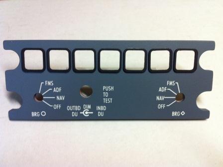
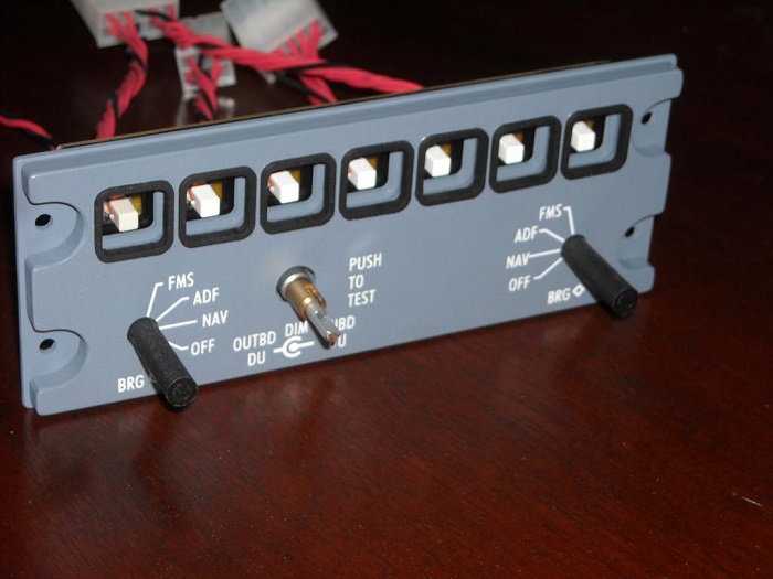
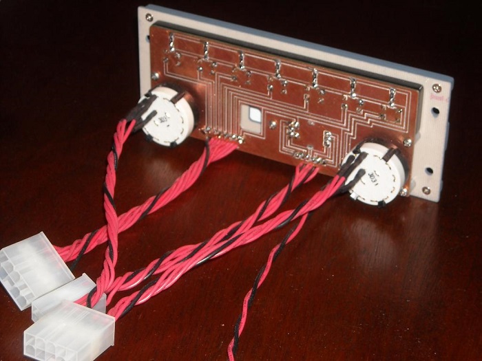
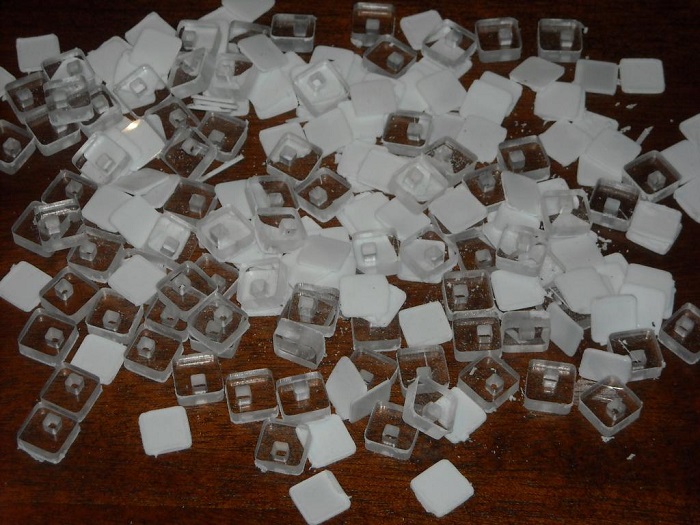
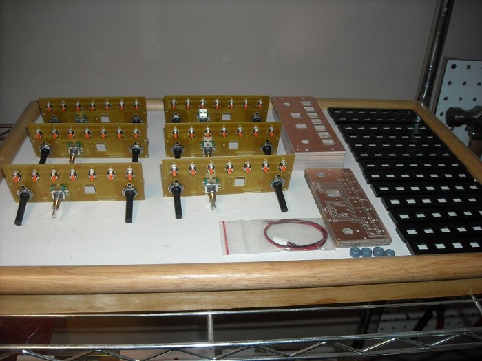
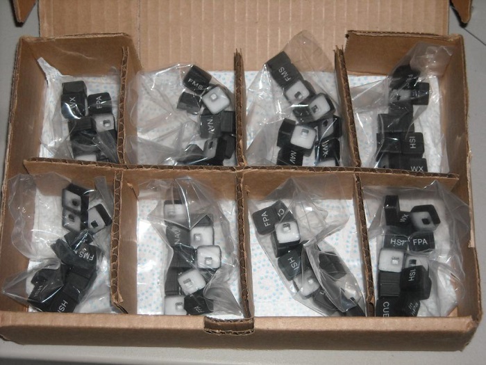
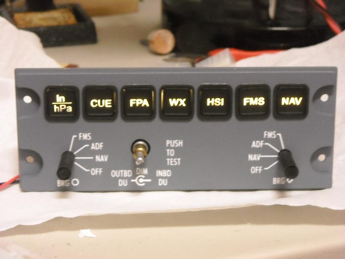
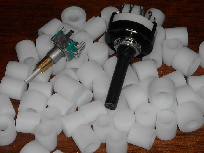
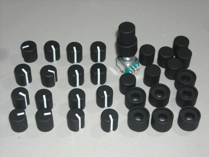
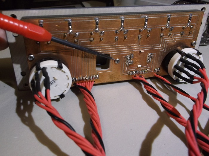
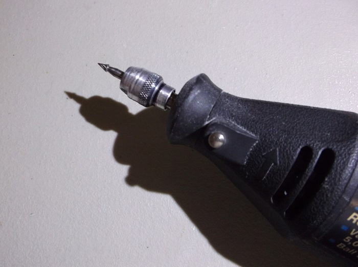
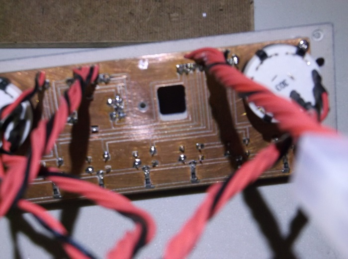
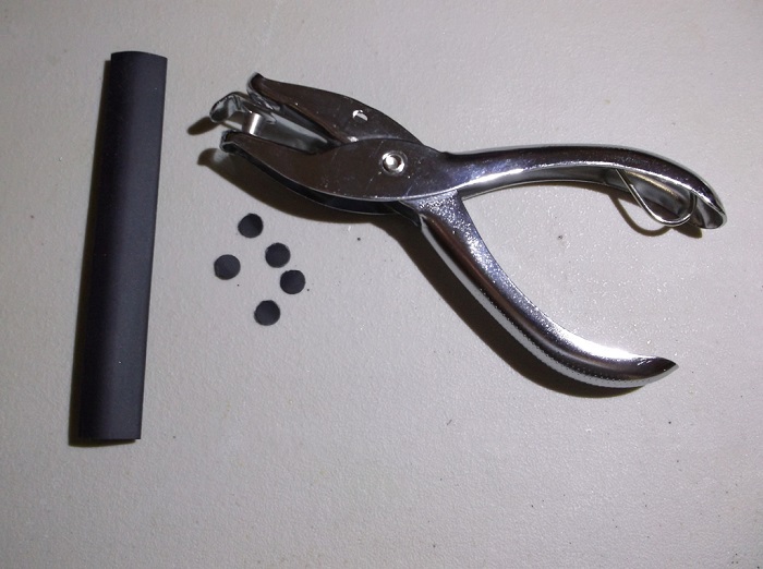
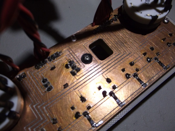
(Original thread started on 06-06-14 by Eric Tomlin) Ron and I have been co-developing EFIS (Electronic Flight Instrument System) Display Controllers to make them available to those that were not able to get a set from Vince. These will be available over the coming weeks. Many of you have contacted us to let us know you are interested in a set. If you have not contacted us to reserve a set, please do so as soon as possible. More info will be provided as pricing becomes final for the entire unit: (Posted by Justin Fletcher on 06-06-14) I'm in, I'm still a ways out, but when the time comes I'd like to have a set of the EFIS panels and the Trim panel. Ron showed me the EFIS prototype; Great craftsmanship. It's awesome you guys do all this on CNC machines in house. (Posted by Ron Rollo on 11-11-14) Eric T. and I are working on the EFIS control panels and the design work is coming along near perfectly. As for what to expect with the EFIS panels? Eric will be working on the front panel and I will be working on the rear in the same manor as we cooperated with the FGC. The back lighting will require 12 volt power as normal and we will offer them in at least two different packages, plug and play and kit form for those of you that like to build things. We will post all updates on the EFIS control panels in this thread. (If you ordered a FGC, don't worry, all FGC orders will be fulfilled prior to the release of the EFIS.) A few months ago I completed the design work of the back side of the EFIS panel and built a prototype. Eric has the front EFIS panel prototype squared away as well. The only thing that is still in the works is the buttons and the knobs. Here is a photo of the prototype to date: And the back side of the EFIS: This design will work effortlessly with the FDS cards being that the inputs are all 8 to 1, meaning that for every set of eight inputs there is one common ground. These EFIS panels will also work with any other interface card, Pokeys, Leo Bodnar, etc..... The pricing for the EFIS panels are as follows: EFIS Panel Kit X2 $550: This will include Eric's front panel ($300) for the set of two and all the hardware for the backer panels including the buttons and knobs which will be supplied by myself ($250). EFIS Panel Head Start X2 $650: This package will include Eric's completed front panels ($300) and the backer panels assembled and all components soldered by myself, ($350). There will be no wires soldered to the backer panels. EFIS Panel Plug and Play X2 $850: This package will include Eric's front panels ($300) and everything listed above plus the wires soldered to the EFIS backers. All the wiring harnesses needed to make both of the EFIS panels plug and play will be included by myself, ($550). We have already taken a few orders for these EFIS panels. If you're in need of a set, please post here or get with either Eric or myself via email. Our expected release will be sometime shortly after the new year. As a side note, because this is a joint effort between myself and Eric, the payment will be split in the same manner as the FGC and the Pitch Trim Panel. (Apologies for any inconvenience in this area) More news and photos to come shortly! UPDATE: Here is a sneak peek at the buttons for the EFIS: The easy part was cutting them out with the CNC. The tedious part is going to be sanding them, one at a time! The buttons are sanded, painted and at the laser shop awaiting engraving. For those who have ordered the Plug and Play version of the EFIS panels, they are about 50% complete. I suspect that they are on scheduled for early January 2015: We have eight sets of button caps ready to be installed into the EFIS panels: UPDATE: Here is another photo of all seven buttons in their right places lit up: Things will slow down over the next week being that Christmas is right around the corner. I have to work Christmas week and we have lots of family coming in town. But don't worry, release will still be the first week or two in January. (Original thread started on 06-06-14 by Eric Tomlin) Ron and I have been co-developing EFIS (Electronic Flight Instrument System) Display Controllers to make them available to those that were not able to get a set from Vince. These will be available over the coming weeks. Many of you have contacted us to let us know you are interested in a set. If you have not contacted us to reserve a set, please do so as soon as possible. More info will be provided as pricing becomes final for the entire unit: (Posted by Justin Fletcher on 06-06-14) I'm in, I'm still a ways out, but when the time comes I'd like to have a set of the EFIS panels and the Trim panel. Ron showed me the EFIS prototype; Great craftsmanship. It's awesome you guys do all this on CNC machines in house. (Posted by Ron Rollo on 11-11-14) Eric T. and I are working on the EFIS control panels and the design work is coming along near perfectly. As for what to expect with the EFIS panels? Eric will be working on the front panel and I will be working on the rear in the same manor as we cooperated with the FGC. The back lighting will require 12 volt power as normal and we will offer them in at least two different packages, plug and play and kit form for those of you that like to build things. We will post all updates on the EFIS control panels in this thread. (If you ordered a FGC, don't worry, all FGC orders will be fulfilled prior to the release of the EFIS.) A few months ago I completed the design work of the back side of the EFIS panel and built a prototype. Eric has the front EFIS panel prototype squared away as well. The only thing that is still in the works is the buttons and the knobs. Here is a photo of the prototype to date: And the back side of the EFIS: This design will work effortlessly with the FDS cards being that the inputs are all 8 to 1, meaning that for every set of eight inputs there is one common ground. These EFIS panels will also work with any other interface card, Pokeys, Leo Bodnar, etc..... The pricing for the EFIS panels are as follows: EFIS Panel Kit X2 $550: This will include Eric's front panel ($300) for the set of two and all the hardware for the backer panels including the buttons and knobs which will be supplied by myself ($250). EFIS Panel Head Start X2 $650: This package will include Eric's completed front panels ($300) and the backer panels assembled and all components soldered by myself, ($350). There will be no wires soldered to the backer panels. EFIS Panel Plug and Play X2 $850: This package will include Eric's front panels ($300) and everything listed above plus the wires soldered to the EFIS backers. All the wiring harnesses needed to make both of the EFIS panels plug and play will be included by myself, ($550). We have already taken a few orders for these EFIS panels. If you're in need of a set, please post here or get with either Eric or myself via email. Our expected release will be sometime shortly after the new year. As a side note, because this is a joint effort between myself and Eric, the payment will be split in the same manner as the FGC and the Pitch Trim Panel. (Apologies for any inconvenience in this area) More news and photos to come shortly! UPDATE: Here is a sneak peek at the buttons for the EFIS: The easy part was cutting them out with the CNC. The tedious part is going to be sanding them, one at a time! The buttons are sanded, painted and at the laser shop awaiting engraving. For those who have ordered the Plug and Play version of the EFIS panels, they are about 50% complete. I suspect that they are on scheduled for early January 2015: We have eight sets of button caps ready to be installed into the EFIS panels: UPDATE: Here is another photo of all seven buttons in their right places lit up: Things will slow down over the next week being that Christmas is right around the corner. I have to work Christmas week and we have lots of family coming in town. But don't worry, release will still be the first week or two in January. UPDATE: I completed all the knobs for the current orders and then some. Here are a few photos of the finished knobs. They turned out near perfect! After cutting and sanding: After the paint process: I am in the process of sending out my part of the EFIS panels to everyone who has an order placed. I have three full sets left over that have not yet been claimed by anyone. Eric's front EFIS panels will soon follow! (Posted by Ron Rollo on 08-07-15) IMPORTANT NOTICE! (Especially those of you who have already received their Project45 EFIS panels) Shane was setting his EFIS panels up and discovered a problem that you might also encounter. There is a potential grounding issue that may need some attention. It is something that I can correct in future EFIS panels so those who have not yet received them, you do not need to worry about this. The issue is the DZUS screws that hold the EFIS panels to the glare shield = GS are actually grounding the EFIS panel to the GS. The EFIS backer clad (which has no electronics on it) is being held in place to the EFIS PCB with five screws. You can see this in a photo in post #7. If the EFIS is not attached to anything you are not going to see an issue. If only one of the EFIS panels is attached to the GS and nothing else, you still will not have an issue. It is only when two or more grounds are conflicting with one another that you will see an issue. Keep in mind that the GS touches the MIP so if you happen to have an improperly grounded panel, screw, LED pin etc... touching either the MIP or the GS you will see an issue. To explain a little further, unfortunately our sim is not like a real airplane when it comes to the common ground. In a real plane, like a car, the frame is the ground. With our sims, the interface cards have their own isolated grounds or commons and only those I/O switches, pots, encoders or rotaries assigned and attached to that card can be associated with that cards ground system. If you happen to have two separate grounds which must be isolated from all others touch each other, you end up with a problem like what Shane experienced. What are some of the clues that you have two grounds conflicting with one another? I had two 12 volt back lighting grounds touching the MIP and GS. In my case one of my panels was lit up twice as bright even with the PWM turned off. I found that one of my back lighting LEDs pins on the REV panel was too long and touching the aluminum GS. Easy fix, I cut the pins shorter so that they would not touch the aluminum GS. In Shane's case, he was having a hot key stroke issue with one of the buttons on the EFIS that was not even assigned an offset. Shane discovered that the ground for the switches on the EFIS which go to one of the FDS cards was somehow touching the GS. How to fix it? My solution would be to remove the five screws that hold the PCB clad to the clad backer. With a Drimel tool or drill bit, remove the copper clad that surrounds those five holes so that the ground current can not cross to those five screws, to the copper clad backer, to the DZUS screws, to the GS and finally to whatever the other ground conflict would be which at the least would be the other EFIS panel. One last thought for you new guys that are not aware how the FDS cards work. It's always worth repeating anyway. The Flight Deck Solution SYS cards are designed to work with isolated common grounds for every eight inputs. That goes for the outputs too for that matter. In other words, if you have eight buttons or switches, there will be one common ground for those eight switches. If you have a ninth input, it will have to go on the next bank of eight with it's own ground. The FDS SYS cards are super star interface cards with it's InterfaceIT software but the common ground issue is just something that you have to be aware of and get use to. All other cards, LeoBodnar, Pokeys, etc... use one common ground for every input that particular card has on it. Even if the card has multiple grounds, they are all the same ground so you don't have to worry about the grounding issue as much. But still, that does not mean you can let a ground from one Pokeys card touch the ground of a totally different Pokeys card or any other card for that matter. I will make the modification to one of the EFIS panels I have on hand and post up some photos for you guys as a bit of a tutorial. Sorry for the headaches! (Posted by Alan Norris on 08-08-15) The other thing to remember with the FDS cards is to ensure that the switch grounds do not come into contact with the LED hot legs. It will not damage the LEDs but will fry the FDS switch card as it puts 12v on the card. (Posted by Ron Rollo on 08-17-15) Sorry for the short delay. I found an easy way to resolve the issue. To recap, the issue is that the PCB that I have all of the components on is also acting as a ground for several of the push buttons. The five screws that hold the PCB to the backer, which is also a blank piece of PCB, is possibly closing a circuit to something else, like back lighting, or another ground that is also touching the glare shield and MIP. By the way, the files have been updated for future EFIS panels so if you don't have one yet, you don't have to worry about this hot fix! So to fix this, we need to isolate the ground to the PCB that all the components are soldered to. And to do that we need to insure that the five screws are no longer conductive or touching the PCB. There are many way to skin a cat and what I have outlined below is just one based on the tools and materials I had on hand. This is the center screw. There are two more at either end: I found that a drill bit with a counter sink can be useful. Also, a Dremel tool like this is a good idea: What you want to do is remove the copper clad away from the hole so that the shaft of the screw has no chance to touch copper. BUT, make sure not to remove too much of the fiberglass part of the PCB. Other wise the screw will go too deep into the face of the backer. You should end up with something like this: Next, I used shrink wrap and a hole punch to make small circular insulators and then popped a small hole in them: And what you end up with is this: Now the screw does not touch the PCB that the components are soldered to which isolates the ground to just that area and not running wildly through your sim causing havoc. Again, I can think of a few other ways to correct this but this seems to be fairly easy. I hope this helps and again, I apologize for the oversight. (Posted by Eric Tomlin 08-17-15) And to add to Ron's post, I too am going to isolate the screws that hold the back-lighting clad in place on this panel as well. In most typical panels with backlighting, this is not required and implemented because typically the hardware plate and front panels either have a gap between them, or there is no exposed clad. Therefore, I will take the extra step to help Ron in isolation too. UPDATE: I completed all the knobs for the current orders and then some. Here are a few photos of the finished knobs. They turned out near perfect! After cutting and sanding: After the paint process: I am in the process of sending out my part of the EFIS panels to everyone who has an order placed. I have three full sets left over that have not yet been claimed by anyone. Eric's front EFIS panels will soon follow! (Posted by Ron Rollo on 08-07-15) IMPORTANT NOTICE! (Especially those of you who have already received their Project45 EFIS panels) Shane was setting his EFIS panels up and discovered a problem that you might also encounter. There is a potential grounding issue that may need some attention. It is something that I can correct in future EFIS panels so those who have not yet received them, you do not need to worry about this. The issue is the DZUS screws that hold the EFIS panels to the glare shield = GS are actually grounding the EFIS panel to the GS. The EFIS backer clad (which has no electronics on it) is being held in place to the EFIS PCB with five screws. You can see this in a photo in post #7. If the EFIS is not attached to anything you are not going to see an issue. If only one of the EFIS panels is attached to the GS and nothing else, you still will not have an issue. It is only when two or more grounds are conflicting with one another that you will see an issue. Keep in mind that the GS touches the MIP so if you happen to have an improperly grounded panel, screw, LED pin etc... touching either the MIP or the GS you will see an issue. To explain a little further, unfortunately our sim is not like a real airplane when it comes to the common ground. In a real plane, like a car, the frame is the ground. With our sims, the interface cards have their own isolated grounds or commons and only those I/O switches, pots, encoders or rotaries assigned and attached to that card can be associated with that cards ground system. If you happen to have two separate grounds which must be isolated from all others touch each other, you end up with a problem like what Shane experienced. What are some of the clues that you have two grounds conflicting with one another? I had two 12 volt back lighting grounds touching the MIP and GS. In my case one of my panels was lit up twice as bright even with the PWM turned off. I found that one of my back lighting LEDs pins on the REV panel was too long and touching the aluminum GS. Easy fix, I cut the pins shorter so that they would not touch the aluminum GS. In Shane's case, he was having a hot key stroke issue with one of the buttons on the EFIS that was not even assigned an offset. Shane discovered that the ground for the switches on the EFIS which go to one of the FDS cards was somehow touching the GS. How to fix it? My solution would be to remove the five screws that hold the PCB clad to the clad backer. With a Drimel tool or drill bit, remove the copper clad that surrounds those five holes so that the ground current can not cross to those five screws, to the copper clad backer, to the DZUS screws, to the GS and finally to whatever the other ground conflict would be which at the least would be the other EFIS panel. One last thought for you new guys that are not aware how the FDS cards work. It's always worth repeating anyway. The Flight Deck Solution SYS cards are designed to work with isolated common grounds for every eight inputs. That goes for the outputs too for that matter. In other words, if you have eight buttons or switches, there will be one common ground for those eight switches. If you have a ninth input, it will have to go on the next bank of eight with it's own ground. The FDS SYS cards are super star interface cards with it's InterfaceIT software but the common ground issue is just something that you have to be aware of and get use to. All other cards, LeoBodnar, Pokeys, etc... use one common ground for every input that particular card has on it. Even if the card has multiple grounds, they are all the same ground so you don't have to worry about the grounding issue as much. But still, that does not mean you can let a ground from one Pokeys card touch the ground of a totally different Pokeys card or any other card for that matter. I will make the modification to one of the EFIS panels I have on hand and post up some photos for you guys as a bit of a tutorial. Sorry for the headaches! (Posted by Alan Norris on 08-08-15) The other thing to remember with the FDS cards is to ensure that the switch grounds do not come into contact with the LED hot legs. It will not damage the LEDs but will fry the FDS switch card as it puts 12v on the card. (Posted by Ron Rollo on 08-17-15) Sorry for the short delay. I found an easy way to resolve the issue. To recap, the issue is that the PCB that I have all of the components on is also acting as a ground for several of the push buttons. The five screws that hold the PCB to the backer, which is also a blank piece of PCB, is possibly closing a circuit to something else, like back lighting, or another ground that is also touching the glare shield and MIP. By the way, the files have been updated for future EFIS panels so if you don't have one yet, you don't have to worry about this hot fix! So to fix this, we need to isolate the ground to the PCB that all the components are soldered to. And to do that we need to insure that the five screws are no longer conductive or touching the PCB. There are many way to skin a cat and what I have outlined below is just one based on the tools and materials I had on hand. This is the center screw. There are two more at either end: I found that a drill bit with a counter sink can be useful. Also, a Dremel tool like this is a good idea: What you want to do is remove the copper clad away from the hole so that the shaft of the screw has no chance to touch copper. BUT, make sure not to remove too much of the fiberglass part of the PCB. Other wise the screw will go too deep into the face of the backer. You should end up with something like this: Next, I used shrink wrap and a hole punch to make small circular insulators and then popped a small hole in them: And what you end up with is this: Now the screw does not touch the PCB that the components are soldered to which isolates the ground to just that area and not running wildly through your sim causing havoc. Again, I can think of a few other ways to correct this but this seems to be fairly easy. I hope this helps and again, I apologize for the oversight. (Posted by Eric Tomlin 08-17-15) And to add to Ron's post, I too am going to isolate the screws that hold the back-lighting clad in place on this panel as well. In most typical panels with backlighting, this is not required and implemented because typically the hardware plate and front panels either have a gap between them, or there is no exposed clad. Therefore, I will take the extra step to help Ron in isolation too.EFIS Panels by Project45 and FLS Discussion
![]()
![]()
2017-10-10