


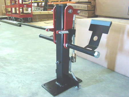
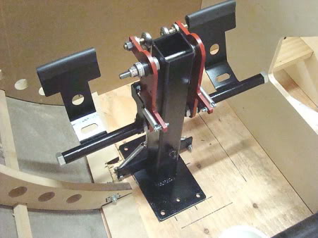
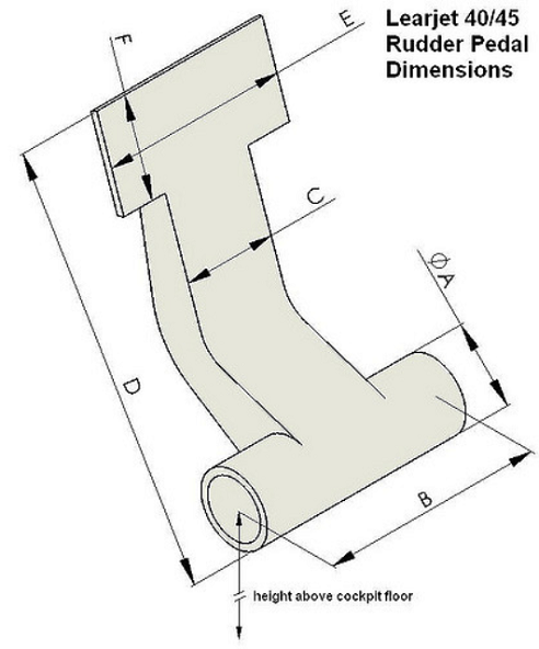
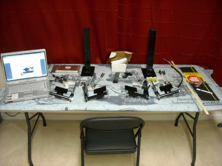
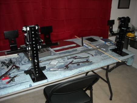
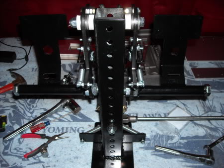
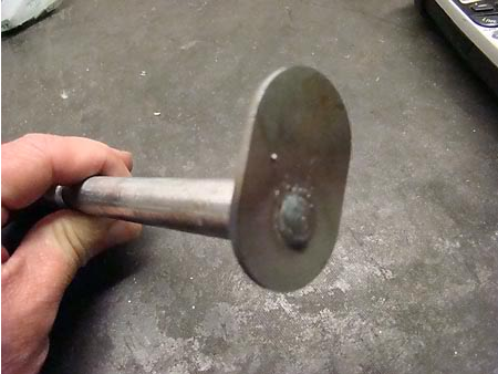
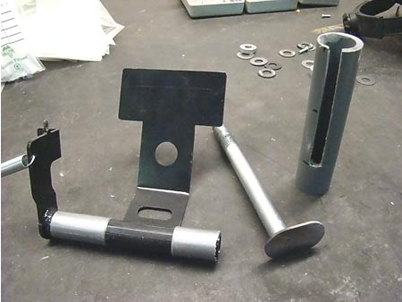
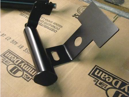
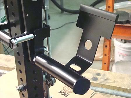
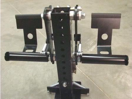
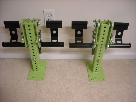
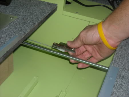
(Original thread started on 01-18-10 by Tom Goldberg) We have been working on a complete set of rudder pedal assemblies for the Lear45 based around Ron's cockpit shell. I can not take full credit for this design as this is similar to Don Jone's design but with some of my own added twists. Thanks Don for the pictures you sent me, it gave me some great ideas! We are still not completely finished with this yet as there are still the pots to mount and a few other details to work out but it gives you the basic idea of what it looks like. One of the key elements to this design is the use of what we call flat torrington bearings. For those of you that don't know what that is, it's a set of small needle roller bearings inserted into a flat disc with a small set of thin thrust washers on each side of the bearing. These little units are placed on each side of the rudder pedal arms and the bell crank so that when you tighten the bolts tight, it will hold the rudder arms solid with no slop or side to side movement, but also creates very little resistance, therefore, the action on the pedals is super smooth. Enjoy the pictures! NOTE: They will be linked together, if you notice the hole in the middle of the bell crank, there will be a linkage running from one to the other. (Posted by Ron Rollo on 01-19-10) Thanks Tom for posting the news and photos! They look very well built! A thousand years from now when we and our projects are nothing but a pile of dust, Tom's Rudder pedals will still be standing and working! Here is a photo of the real Lear45 rudder pedals: Note that the hump, or cover of the mechanism is 5" Wide. Drawing of a Lear45 rudder pedal provided by Mike: (Posted by Eric Tomlin on 02-22-10) Tom sent over the Rudder Pedal Assembly Guide to Ron and I so I created a new page under Resources where the guide is now located for you to download and view. You can find it HERE (Posted by Alaxus on 02-23-10) Nice looking setup! I noticed though that the original Lear pedal assemblies have a parallelogram action to keep the pedals at the same angle regardless of the position of the arms. I assume you left this out for simplicity? (Posted by Tom Goldberg on 02-23-10) Hi Alaxus, I certainly understand what you are talking about with the pedal angle, so to answer your question, yes, simplicity and affordability are key issues here. To try to do what you are talking about would be way to complicated for what we need. this is one reason we built the pedals with an adjustable toe brake setup so you can adjust the pedals to your liking and it seems to work fine with really no issues. But these are not CH pedals and you will have to get used to them. Also seat height and distance from the pedals all play a roll in how you will adjust them for comfort. (Posted by Ron Rollo on 03-10-10) I am the proud owner of the first set of Tom's rudder pedals! They arrived yesterday and I opened the box about an hour ago. Heavy metal and re-balancing the airframe comes to mind because now the shell is nose heavy! Very thick aluminum and good quality parts Tom. I don't think we will be worried about putting too much force on them. It only took about 3 hours to put them together by the book. I don't have the Pots installed yet and they are not in the sim but I can already see that they are going to do the job very well for me. I was looking for three things in a pedal assembly: 1. They look like the real Lear45 pedals. 2. They are dual connected. 3. They have toe brakes! Here is everything set out ready to be put together: Three hours later! A close up of the Pilot's set: All in all, I would give this pedal set design an A+. There are only minor things that I plan to do. I will share them with you as I move forward with the work! Thanks Tom for you hard work on this project! (Posted by Shane Barnes on 03-12-10) Thanks for the update Ron. I am the owner of the second set and the parts look great. I have not had time to assemble them yet, but the parts are first rate, as you said heavy construction. Tom, thanks again for designing the Lear rudder pedals, these will really look awesome in the shell. (Posted by Tom Goldberg on 04-02-10) Here is a small update kit for the rudder pedal set. Basically all it consists of is the pedal tube end cap and you will need to get some 1" gray PVC,which actually measures around an 1 1/4" O.D. This gives us a little more scale appearance to the pedal tube and with the end cap a little more realistic look. Procedure is: Cut bolt head off of pedal tube bolt with Dremel tool. There is a hole in the middle of the end cap. Stick the end cap on top of the bolt shank and weld in the hole. Grind the end flush so no weld is left and looks clean. The PVC has a slot cut down it to go over the pedal itself, then cut to correct length. The I.D. of the PVC is just a little larger than the O.D. of the original pedal tube but not to much. I just used a couple pieces of duct tape wrapped around the tube to take up some space for a snug fit when the PVC tube is slid over it. Paint it up and your done. Seems to work great!
(Original thread started on 01-18-10 by Tom Goldberg) We have been working on a complete set of rudder pedal assemblies for the Lear45 based around Ron's cockpit shell. I can not take full credit for this design as this is similar to Don Jone's design but with some of my own added twists. Thanks Don for the pictures you sent me, it gave me some great ideas! We are still not completely finished with this yet as there are still the pots to mount and a few other details to work out but it gives you the basic idea of what it looks like. One of the key elements to this design is the use of what we call flat torrington bearings. For those of you that don't know what that is, it's a set of small needle roller bearings inserted into a flat disc with a small set of thin thrust washers on each side of the bearing. These little units are placed on each side of the rudder pedal arms and the bell crank so that when you tighten the bolts tight, it will hold the rudder arms solid with no slop or side to side movement, but also creates very little resistance, therefore, the action on the pedals is super smooth. Enjoy the pictures! NOTE: They will be linked together, if you notice the hole in the middle of the bell crank, there will be a linkage running from one to the other. (Posted by Ron Rollo on 01-19-10) Thanks Tom for posting the news and photos! They look very well built! A thousand years from now when we and our projects are nothing but a pile of dust, Tom's Rudder pedals will still be standing and working! Here is a photo of the real Lear45 rudder pedals: Note that the hump, or cover of the mechanism is 5" Wide. Drawing of a Lear45 rudder pedal provided by Mike: (Posted by Eric Tomlin on 02-22-10) Tom sent over the Rudder Pedal Assembly Guide to Ron and I so I created a new page under Resources where the guide is now located for you to download and view. You can find it HERE (Posted by Alaxus on 02-23-10) Nice looking setup! I noticed though that the original Lear pedal assemblies have a parallelogram action to keep the pedals at the same angle regardless of the position of the arms. I assume you left this out for simplicity? (Posted by Tom Goldberg on 02-23-10) Hi Alaxus, I certainly understand what you are talking about with the pedal angle, so to answer your question, yes, simplicity and affordability are key issues here. To try to do what you are talking about would be way to complicated for what we need. this is one reason we built the pedals with an adjustable toe brake setup so you can adjust the pedals to your liking and it seems to work fine with really no issues. But these are not CH pedals and you will have to get used to them. Also seat height and distance from the pedals all play a roll in how you will adjust them for comfort. (Posted by Ron Rollo on 03-10-10) I am the proud owner of the first set of Tom's rudder pedals! They arrived yesterday and I opened the box about an hour ago. Heavy metal and re-balancing the airframe comes to mind because now the shell is nose heavy! Very thick aluminum and good quality parts Tom. I don't think we will be worried about putting too much force on them. It only took about 3 hours to put them together by the book. I don't have the Pots installed yet and they are not in the sim but I can already see that they are going to do the job very well for me. I was looking for three things in a pedal assembly: 1. They look like the real Lear45 pedals. 2. They are dual connected. 3. They have toe brakes! Here is everything set out ready to be put together: Three hours later! A close up of the Pilot's set: All in all, I would give this pedal set design an A+. There are only minor things that I plan to do. I will share them with you as I move forward with the work! Thanks Tom for you hard work on this project! (Posted by Shane Barnes on 03-12-10) Thanks for the update Ron. I am the owner of the second set and the parts look great. I have not had time to assemble them yet, but the parts are first rate, as you said heavy construction. Tom, thanks again for designing the Lear rudder pedals, these will really look awesome in the shell. (Posted by Tom Goldberg on 04-02-10) Here is a small update kit for the rudder pedal set. Basically all it consists of is the pedal tube end cap and you will need to get some 1" gray PVC,which actually measures around an 1 1/4" O.D. This gives us a little more scale appearance to the pedal tube and with the end cap a little more realistic look. Procedure is: Cut bolt head off of pedal tube bolt with Dremel tool. There is a hole in the middle of the end cap. Stick the end cap on top of the bolt shank and weld in the hole. Grind the end flush so no weld is left and looks clean. The PVC has a slot cut down it to go over the pedal itself, then cut to correct length. The I.D. of the PVC is just a little larger than the O.D. of the original pedal tube but not to much. I just used a couple pieces of duct tape wrapped around the tube to take up some space for a snug fit when the PVC tube is slid over it. Paint it up and your done. Seems to work great!
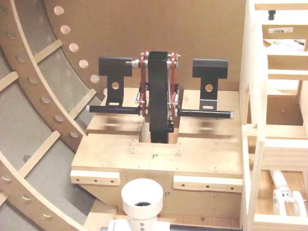
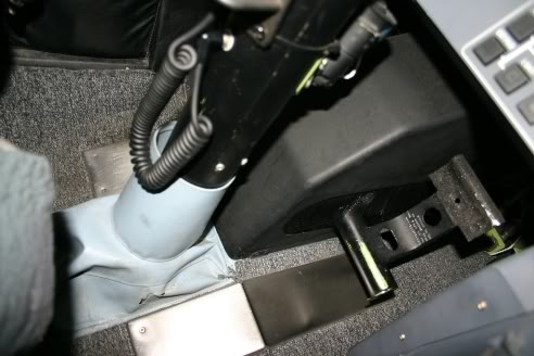
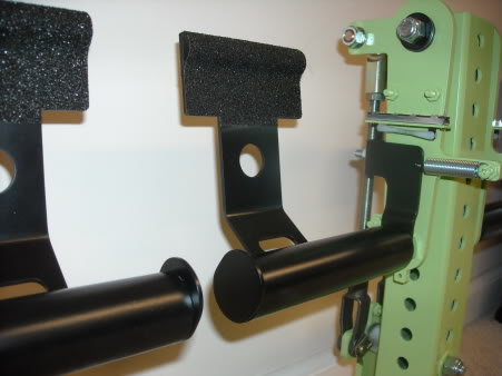
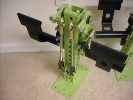
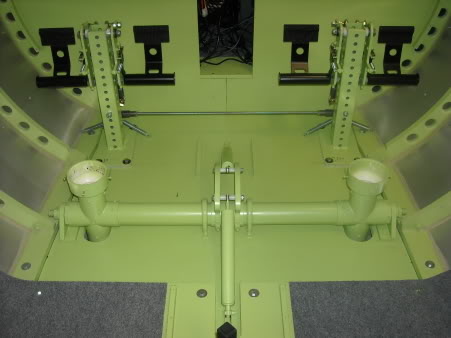
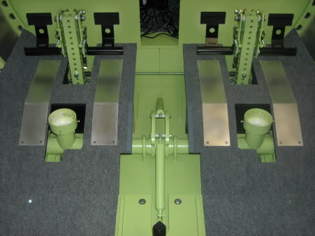
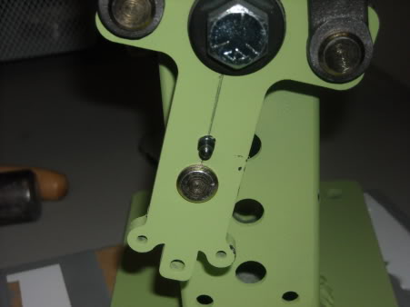
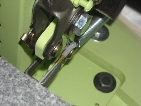
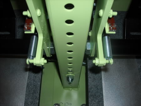
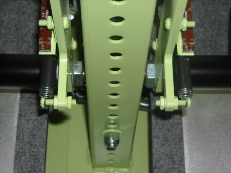
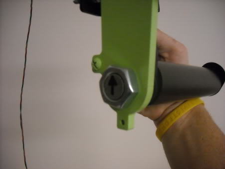
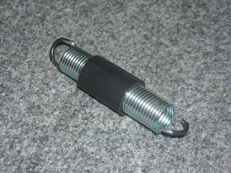
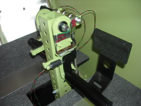
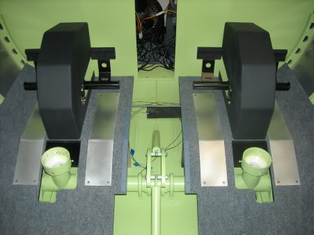
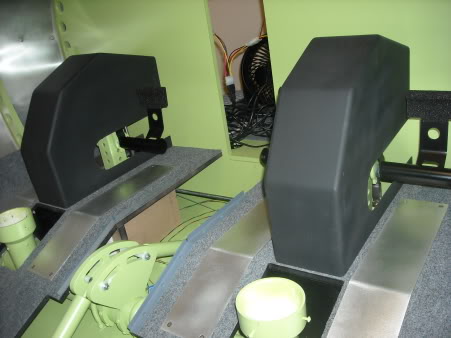
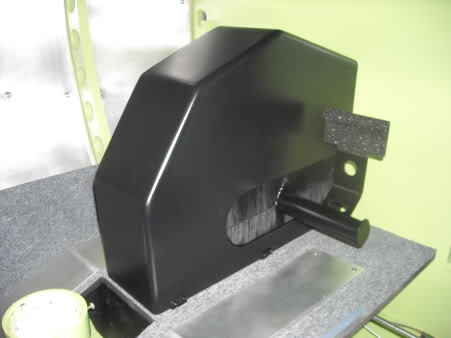
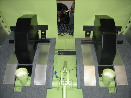
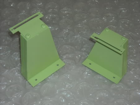
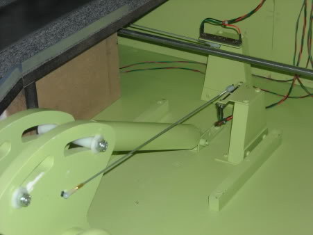
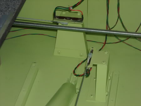
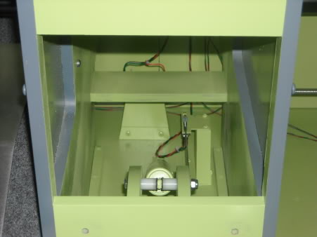
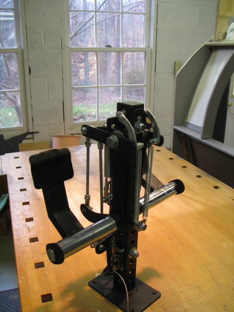
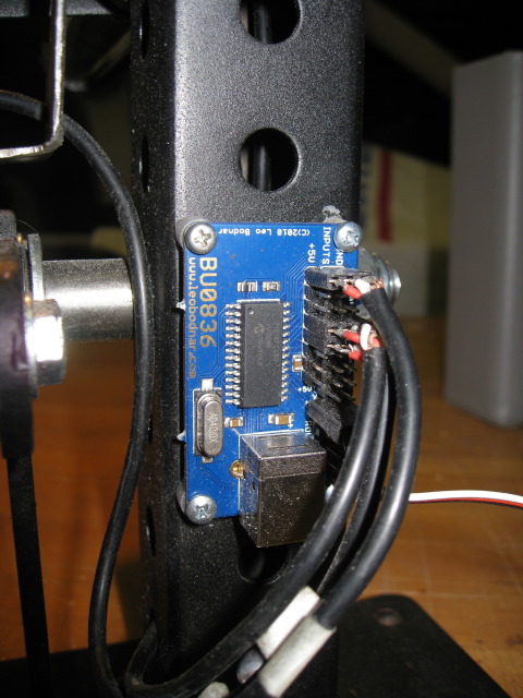
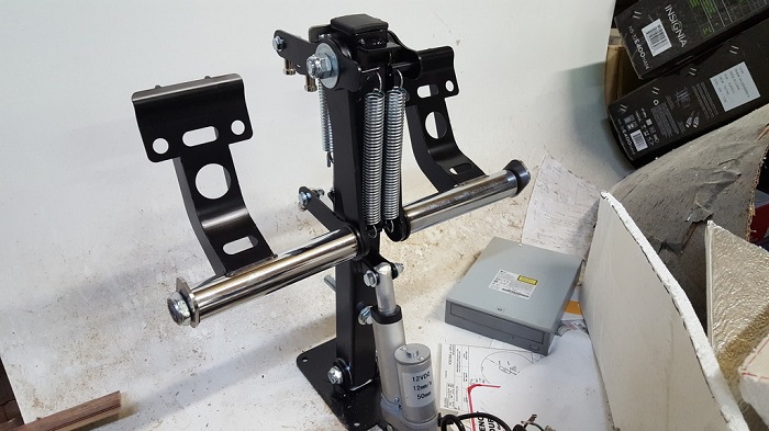
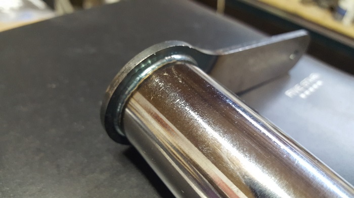
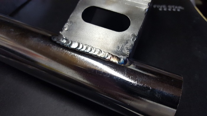
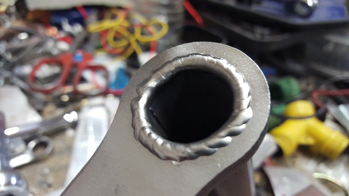
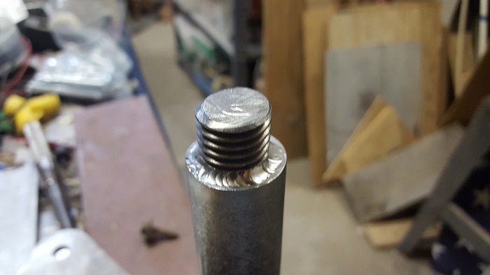
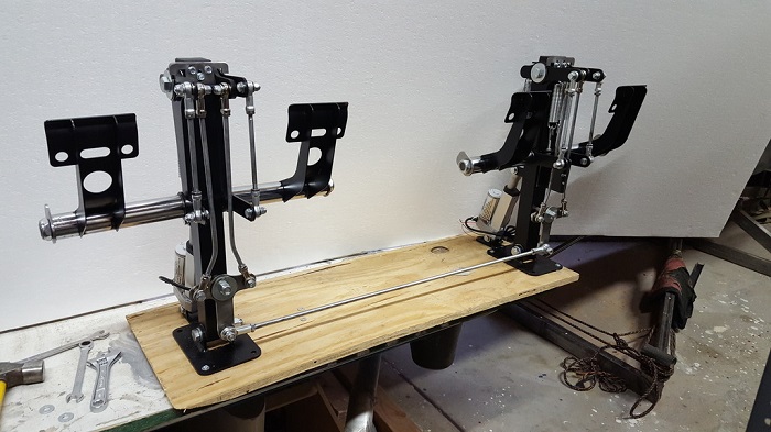
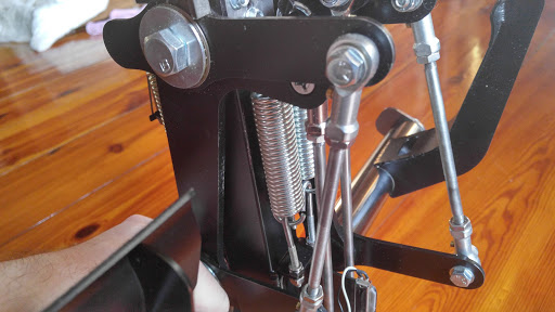
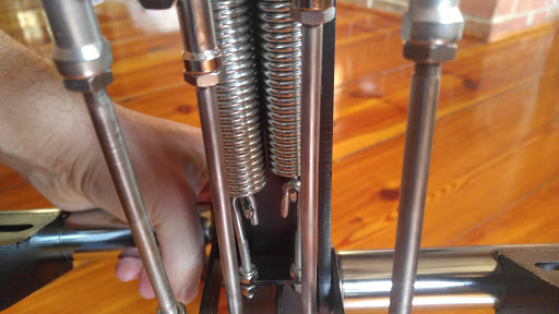
(Posted by Ron Rollo on 06-22-10) I just finished up my mods to the rudder pedal system that I have from Tom. My goal was to make them look and feel as good as possible. I need to thank Tom again for providing the basics to work with. Here is a short list of things that I did and others can do also: 1. Added several locking washers to stop bolts to insure they don't work there way loose. 2. I found another main pivot bolt at the top that had a about .5" more thread so I could discard one of the larger spacers. This allows me to make the rudder box a little smaller. 3. I took about 3/8th" off of the oval end caps that Tom sent, cut the bolt head off the pedal pivot and welded them to the bolt. (Like Tom did above) 4. Added PVC tubing to thicken up the look of the main pedal part and caulking to hold it in place. It is a nice solid feeling. 5. Painted the rudder pedal tower airframe green and the pedals flat black. I also painted the pedals airframe green under the flat black so that with time, as the flat black wears off, the green will show in it's place! 6. Added a curved piece of wood to the top end of the pedal plate and added anti skid material. (This is one of my favorite parts) 7. Greased the main pedal bolts so that when brakes are applied, it is quite and feels smooth. 8. I removed the self contained spring system that brings the pedals back to center. I will use two springs and attach them to the base floor. This means less cutting and notching to do to the shell frame. 9. I am using the aluminum plate that Tom supplied to go directly under the pedal assembly rather than under the base floor. This will raise the pedal assembly up about .25". 10. (Not pictured) I will be adding a slider POT to capture 100% of the pedal movements. Check out these photos of the updated mods: Again, thank you Tom for providing this pedal kit! None of this could have been possible without your hard work on this part of the build. Here are some more images of the recent work I have been doing on the rudder pedal system. I have them installed with the return springs and the POT just about installed. Take note of the four return springs. After I installed the raised floor section, I found that the rudders were a little too tight, so I released the two inside springs so that only the two outside springs are working. This feels really good: I spent most of a whole day trying to find the perfect position for the rudder towers. Once they are bolted down, they are not moving. The real L45 has a pedal system that adjust forward and aft with the flip of a momentary toggle switch. There may be a day in the future (years down the road) when I revisit the rudder pedal system and build a few more features into them: Here is the big deal. I attached a little round ball that a socket will fit onto. It took a few minutes to find just the right point to capture 100% of the rudder pedal movement and at the same time using 98% of the travel on the POT: Here you can see the transfer rod that heads over to the center of the TQ pedestal: Here is the POT bracket near the center of the bottom of the TQ pedestal. Now all I need to do is make a stand for it, wire it up and then make a shield to protect it from others cables and wires. I plan to do the same thing with the pitch POT on the columns: (Posted by Ron Rollo on 09-09-10) I discovered that the springs on the toe brakes were not strong enough when we are working the rudders back and forth. In other words, the brakes are inadvertently applied because they slip under our feet when the rudder arms are swinging back and forth. To fix this issue, I replaced the springs with a slightly shorter spring to give the brakes more tension. The spring on the left is the new shorter spring. Now the brakes do not slip under my feet and they are about twice as hard to apply which feels very nice. You can find these springs at Ace Hardware: Another issue that I just had to do something about is the noise that the springs make. I took a one inch piece of shrink wrap and slid it over the springs so that it dampened the "doying" effect. This is something that I plan to do to all the springs in my simulator. Just some ideas to share with you guys! In order to get the rudder pedal assemblies to fit inside my rudder pedal covers, I had to make them a little thinner. By the end of the day, I was able to take over a half inch out of the width of the original design by doing a little swapping and shaving. In this picture, I had to shave down the bolt so that it was flush with the nut. Then I put my indicator arrow back on the end of the bolt. The arrow indicates which direction the bolt fits best within the brake pedal assembly: My springs were too noisy so I found a way to hush them up. I used shrink wrap at the ends and a plastic sleeve that fits loosely over it to keep it quite: Wiring the slider pots were a bit tricky because these are moving parts. In most switches and buttons, they are stationary and once you have a good solder, your done. But in the case of the pedals, they move! So the idea is to secure the wires so that there is absolutely no movement at the solder points. I used aluminum tape to secure the wire to the pedal arms in two different places: And this is where I am at after another week of working on them: Clearly I need to install the dust brushes to cover up the internal pedal assemblies. One more update next week and this phase of my project will be complete! Additionally, I have finally finished my rudder pedal covers. Here are a few pictures: The brushes work perfectly! You can read more about my rudder pedal covers HERE AT this point, Shane and I are about at the same point in our builds. We need to get at least one interface card so that we can test some of our flight controls that we have been working on. Up until this point, it has been all about mechanics and working the little issues out of things. The only thing that the interface card is concerned with is the POT (potentiometer) . I have set my linkages and pivot points to capture nearly 100% of the travel of the POT in all cases. This will increase the sensitivity on the controls so that any slight movement will be picked up by the POT. (Posted by Shane Barnes on 09-23-10) If I have counted correctly we will need an interface card that has 11 axis inputs, but there is no such card. We will need more than one card if not three in total. Here is a breakdown of the POTs needed in our sims: The control column/yoke assembly will require two axis, the rudder assembly will require 5 axis, and the TQ will require 4 axis. Any suggestions on the best interface cards to use? I've been looking at the one from FDS. I found this board, price including shipping is around $34.00. It supports 8 axis: http://www.leobodnar.com/products/BU0836/ Or this one for $60.00 including shipping: http://www.leobodnar.com/products/BU0836A/ (Posted by Ron Rollo on 09-23-10) Currently there is not an interface board that can handle all eleven POTs that we have. So at best, we would need to purchase two cards. Vince suggested the Pokey card. I think they have 6 each. As for wiring up your four toe brakes, simply run four sets of pot wires from their brake pedal pots to an interface card that can handle analog signals. Pokeys and Leo Bodnar cards as examples just to name a few. By using FSUIPC you can program as many LEFT brake pots and as many RIGHT brake pots as you want with no issues as long as you make sure of just one thing...... NOTE: Before I get into the "one thing" that you have to make sure of, let me first explain that it is easy to connect up one set of pedals. You can't mess that up. In the next paragraph, when I compare the two toe brakes, I am talking about the pilots left toe brake and the co-pilots left toe brake. These are the signals that we are wanting to work well with each other. Same goes for the right toe brakes. The only trick is to make sure that the pots are all facing the same direction so that FSUIPC does not get conflicting signals. In other words, one pot being backwards would be trying to put the brakes on and the other pot being correct would be at rest even though they are both physically at rest. If set up correctly, all the pots, (in our case four: left CPT, right CPT, left CP and right CP) should be at or close to 0 ohms while at rest. Then when either pedal or both pedals are pressed, FSUIPC picks up on it and applies braking. If you are not familiar with FSUIPC, you will be by the time you are finished with your project! (Posted by Eric Tomlin on 09-23-10) Having two pots sending a signal for a single item (like a brake since you mentioned it) isn't a problem when using a USB device like CH yokes/pedals. I don't see any issues with this either. For example, I have 2 CH yokes connected via USB to the same USB hub. As long as the two aren't moved at the same time, then there's no conflict. You simply calibrate them via FSUIPC and you're done with it. Again, I would focus more on finding a card you like than worrying about conflicts. Pokeys is a great value and highly recommended. The FDS card is surely a great piece but is a little expensive compared to other similar devices. (Posted by Ron Rollo on 09-24-10) One more update to the rudder pedals. I completed the POT towers for the YAW and the pitch axis today. They are made out of wood and aluminum "L" angle. I used two of Tom's POT brackets at the top: The same rules apply to both of these Pots. You can clearly see the pivot point on the pitch. It takes a little time but the idea is to find the spot that gives you maximum travel but does not bind the travel rod or put tension on the POT. In my case, I was able to capture 95% to 98% of the POT: Another thing that I got schooled on was the wiring. I was using a very small, maybe 24 or 26 gauge solid wire. It was actually alarm system wire. As a matter of fact, it is still wired up to the toe brakes in this picture. I found that 22 gauge stranded wire works best. 20 gauge will also work but you get much more wire on the spool with the 22 gauge: In this picture, the TQ is in place. Notice the cross over that helps protect the linkages? I will end up putting at least one more in the lower end of the TQ. This is so that all the large and heavy cables will have something to rest on rather than pushing or being up against the mechanical linkage arms: (Posted by Ron Rollo on 06-22-10) I just finished up my mods to the rudder pedal system that I have from Tom. My goal was to make them look and feel as good as possible. I need to thank Tom again for providing the basics to work with. Here is a short list of things that I did and others can do also: 1. Added several locking washers to stop bolts to insure they don't work there way loose. 2. I found another main pivot bolt at the top that had a about .5" more thread so I could discard one of the larger spacers. This allows me to make the rudder box a little smaller. 3. I took about 3/8th" off of the oval end caps that Tom sent, cut the bolt head off the pedal pivot and welded them to the bolt. (Like Tom did above) 4. Added PVC tubing to thicken up the look of the main pedal part and caulking to hold it in place. It is a nice solid feeling. 5. Painted the rudder pedal tower airframe green and the pedals flat black. I also painted the pedals airframe green under the flat black so that with time, as the flat black wears off, the green will show in it's place! 6. Added a curved piece of wood to the top end of the pedal plate and added anti skid material. (This is one of my favorite parts) 7. Greased the main pedal bolts so that when brakes are applied, it is quite and feels smooth. 8. I removed the self contained spring system that brings the pedals back to center. I will use two springs and attach them to the base floor. This means less cutting and notching to do to the shell frame. 9. I am using the aluminum plate that Tom supplied to go directly under the pedal assembly rather than under the base floor. This will raise the pedal assembly up about .25". 10. (Not pictured) I will be adding a slider POT to capture 100% of the pedal movements. Check out these photos of the updated mods: Again, thank you Tom for providing this pedal kit! None of this could have been possible without your hard work on this part of the build. Here are some more images of the recent work I have been doing on the rudder pedal system. I have them installed with the return springs and the POT just about installed. Take note of the four return springs. After I installed the raised floor section, I found that the rudders were a little too tight, so I released the two inside springs so that only the two outside springs are working. This feels really good: I spent most of a whole day trying to find the perfect position for the rudder towers. Once they are bolted down, they are not moving. The real L45 has a pedal system that adjust forward and aft with the flip of a momentary toggle switch. There may be a day in the future (years down the road) when I revisit the rudder pedal system and build a few more features into them: Here is the big deal. I attached a little round ball that a socket will fit onto. It took a few minutes to find just the right point to capture 100% of the rudder pedal movement and at the same time using 98% of the travel on the POT: Here you can see the transfer rod that heads over to the center of the TQ pedestal: Here is the POT bracket near the center of the bottom of the TQ pedestal. Now all I need to do is make a stand for it, wire it up and then make a shield to protect it from others cables and wires. I plan to do the same thing with the pitch POT on the columns: (Posted by Ron Rollo on 09-09-10) I discovered that the springs on the toe brakes were not strong enough when we are working the rudders back and forth. In other words, the brakes are inadvertently applied because they slip under our feet when the rudder arms are swinging back and forth. To fix this issue, I replaced the springs with a slightly shorter spring to give the brakes more tension. The spring on the left is the new shorter spring. Now the brakes do not slip under my feet and they are about twice as hard to apply which feels very nice. You can find these springs at Ace Hardware: Another issue that I just had to do something about is the noise that the springs make. I took a one inch piece of shrink wrap and slid it over the springs so that it dampened the "doying" effect. This is something that I plan to do to all the springs in my simulator. Just some ideas to share with you guys! In order to get the rudder pedal assemblies to fit inside my rudder pedal covers, I had to make them a little thinner. By the end of the day, I was able to take over a half inch out of the width of the original design by doing a little swapping and shaving. In this picture, I had to shave down the bolt so that it was flush with the nut. Then I put my indicator arrow back on the end of the bolt. The arrow indicates which direction the bolt fits best within the brake pedal assembly: My springs were too noisy so I found a way to hush them up. I used shrink wrap at the ends and a plastic sleeve that fits loosely over it to keep it quite: Wiring the slider pots were a bit tricky because these are moving parts. In most switches and buttons, they are stationary and once you have a good solder, your done. But in the case of the pedals, they move! So the idea is to secure the wires so that there is absolutely no movement at the solder points. I used aluminum tape to secure the wire to the pedal arms in two different places: And this is where I am at after another week of working on them: Clearly I need to install the dust brushes to cover up the internal pedal assemblies. One more update next week and this phase of my project will be complete! Additionally, I have finally finished my rudder pedal covers. Here are a few pictures: The brushes work perfectly! You can read more about my rudder pedal covers HERE AT this point, Shane and I are about at the same point in our builds. We need to get at least one interface card so that we can test some of our flight controls that we have been working on. Up until this point, it has been all about mechanics and working the little issues out of things. The only thing that the interface card is concerned with is the POT (potentiometer) . I have set my linkages and pivot points to capture nearly 100% of the travel of the POT in all cases. This will increase the sensitivity on the controls so that any slight movement will be picked up by the POT. (Posted by Shane Barnes on 09-23-10) If I have counted correctly we will need an interface card that has 11 axis inputs, but there is no such card. We will need more than one card if not three in total. Here is a breakdown of the POTs needed in our sims: The control column/yoke assembly will require two axis, the rudder assembly will require 5 axis, and the TQ will require 4 axis. Any suggestions on the best interface cards to use? I've been looking at the one from FDS. I found this board, price including shipping is around $34.00. It supports 8 axis: http://www.leobodnar.com/products/BU0836/ Or this one for $60.00 including shipping: http://www.leobodnar.com/products/BU0836A/ (Posted by Ron Rollo on 09-23-10) Currently there is not an interface board that can handle all eleven POTs that we have. So at best, we would need to purchase two cards. Vince suggested the Pokey card. I think they have 6 each. As for wiring up your four toe brakes, simply run four sets of pot wires from their brake pedal pots to an interface card that can handle analog signals. Pokeys and Leo Bodnar cards as examples just to name a few. By using FSUIPC you can program as many LEFT brake pots and as many RIGHT brake pots as you want with no issues as long as you make sure of just one thing...... NOTE: Before I get into the "one thing" that you have to make sure of, let me first explain that it is easy to connect up one set of pedals. You can't mess that up. In the next paragraph, when I compare the two toe brakes, I am talking about the pilots left toe brake and the co-pilots left toe brake. These are the signals that we are wanting to work well with each other. Same goes for the right toe brakes. The only trick is to make sure that the pots are all facing the same direction so that FSUIPC does not get conflicting signals. In other words, one pot being backwards would be trying to put the brakes on and the other pot being correct would be at rest even though they are both physically at rest. If set up correctly, all the pots, (in our case four: left CPT, right CPT, left CP and right CP) should be at or close to 0 ohms while at rest. Then when either pedal or both pedals are pressed, FSUIPC picks up on it and applies braking. If you are not familiar with FSUIPC, you will be by the time you are finished with your project! (Posted by Eric Tomlin on 09-23-10) Having two pots sending a signal for a single item (like a brake since you mentioned it) isn't a problem when using a USB device like CH yokes/pedals. I don't see any issues with this either. For example, I have 2 CH yokes connected via USB to the same USB hub. As long as the two aren't moved at the same time, then there's no conflict. You simply calibrate them via FSUIPC and you're done with it. Again, I would focus more on finding a card you like than worrying about conflicts. Pokeys is a great value and highly recommended. The FDS card is surely a great piece but is a little expensive compared to other similar devices. (Posted by Ron Rollo on 09-24-10) One more update to the rudder pedals. I completed the POT towers for the YAW and the pitch axis today. They are made out of wood and aluminum "L" angle. I used two of Tom's POT brackets at the top: The same rules apply to both of these Pots. You can clearly see the pivot point on the pitch. It takes a little time but the idea is to find the spot that gives you maximum travel but does not bind the travel rod or put tension on the POT. In my case, I was able to capture 95% to 98% of the POT: Another thing that I got schooled on was the wiring. I was using a very small, maybe 24 or 26 gauge solid wire. It was actually alarm system wire. As a matter of fact, it is still wired up to the toe brakes in this picture. I found that 22 gauge stranded wire works best. 20 gauge will also work but you get much more wire on the spool with the 22 gauge: In this picture, the TQ is in place. Notice the cross over that helps protect the linkages? I will end up putting at least one more in the lower end of the TQ. This is so that all the large and heavy cables will have something to rest on rather than pushing or being up against the mechanical linkage arms: (Posted by Alan Norris on 12-12-12) Got an early Christmas present from Randy today, pedals! Nice job Randy! Bloody heavy! Here's the Leo Bodnar board. Not sure what that little push button that is wired to the board does: Without a doubt, these pedals more closely resemble the real Lear45 pedal motion. Although the brake springs may need to be a little stronger but time will tell. (Posted by Ron Rollo on 06-21-17) Some of you are aware that long time Hamgar45 member Randy Buchanan has been working hard on a new design for the rudder pedals which includes the "parallelogram feature" that is found in the real Lear45 and most other advanced aircraft. This designs basically keeps the angel of the toe brake pedals at the same angle no matter if they are in the center (neutral), hard left or hard right positions. The angle of the toe brake pedals only change if we are to apply braking to that pedal at which time it will angle back like you are pressing a gas pedal in a vehicle. This is the correct way the pedals should work! Additionally, Randy has implemented into his design the feature to adjust the position of the pedals forward or back by using a mechanical motor and the PEDAL ADJUST momentary toggles on the outboard lower panels, again, just like what you would find in the real Lear45! Congrats to Randy for taking the pedals to an all new level of functionality! Here is a photo of one of his prototype pedal assemblies several months ago: And here are a couple photos of Randy's superb welding skills! This is a photo of the custom threaded pedal shaft he has designed: Maciej is one of the first members of Hangar45 to get a dual set of Randy's rudder pedals. You may have already seen them in his build thread: Here are a couple photos of the assembled linkage arms: If you guys have a set of Randy's rudder pedal assemblies and have a few tips on how to install them and finish them off please post your photos and findings here! (Posted by Alan Norris on 12-12-12) Got an early Christmas present from Randy today, pedals! Nice job Randy! Bloody heavy! Here's the Leo Bodnar board. Not sure what that little push button that is wired to the board does: Without a doubt, these pedals more closely resemble the real Lear45 pedal motion. Although the brake springs may need to be a little stronger but time will tell. (Posted by Ron Rollo on 06-21-17) Some of you are aware that long time Hamgar45 member Randy Buchanan has been working hard on a new design for the rudder pedals which includes the "parallelogram feature" that is found in the real Lear45 and most other advanced aircraft. This designs basically keeps the angel of the toe brake pedals at the same angle no matter if they are in the center (neutral), hard left or hard right positions. The angle of the toe brake pedals only change if we are to apply braking to that pedal at which time it will angle back like you are pressing a gas pedal in a vehicle. This is the correct way the pedals should work! Additionally, Randy has implemented into his design the feature to adjust the position of the pedals forward or back by using a mechanical motor and the PEDAL ADJUST momentary toggles on the outboard lower panels, again, just like what you would find in the real Lear45! Congrats to Randy for taking the pedals to an all new level of functionality! Here is a photo of one of his prototype pedal assemblies several months ago: And here are a couple photos of Randy's superb welding skills! This is a photo of the custom threaded pedal shaft he has designed: Maciej is one of the first members of Hangar45 to get a dual set of Randy's rudder pedals. You may have already seen them in his build thread: Here are a couple photos of the assembled linkage arms: If you guys have a set of Randy's rudder pedal assemblies and have a few tips on how to install them and finish them off please post your photos and findings here! Hey guys, I am in the process of reinstalling my Tom Goldberg pedal set back into my sim. A hurdle I had to overcome before I could do this was to line up the pedals directly behind the control columns. The limiting factor is shell base plate which is right there and I have already cut into it as much as I can. After a few days of working on a solution, the only viable option was to bite the bullet and replace the bottom mounting plates which are welded to the 2 inch square tubing. Not what I wanted to do, but this was the only option to move forward. I used a standard Dremel tool and a 90 degree head to grind down the welds. Here you can clearly see that the 2 inch square tubing was welded in the center of the mounting plate. I designed a set of mounting plates in dxf and had them made using an online waterjet service. These new plates have the 2 inch square tubing offset outboard by about a half inch. Additionally, I made the four mounting holes oblong so that I could fine tune the mounting points if needed so that the pedals are exactly lined up behind the control columns. Sanded and painted with primer. Again, this was a lot of work, took some time and cost a little ,but well worth it. Remember, this pedal set is the old Tom Goldberg design and I am reinstalling them for now until I have time to work on my new pedal design. But in order to save time in the long run, this pedal set has to be mounted properly behind the control columns. This way, the new and improved raised floor sections only have to be made once. Here is a close up of the First Officer's mounting plates. Notice the 2 inch square tubing is now set further outboard. Additionally, I added a thin foam bottom to the mounting plate to give me the ability to fine tune them if they are not perfectly straight up and down. Here they are rebuilt and ready to be reinstalled back into the sim. And here they are installed, now perfectly lined up behind the control columns. Notice I don't have them bolted down yet because I still have to make and add a couple riser plates to bring the pedal height up slightly. The amount of lift will be between 1/4" to 1/2", the exact number is still to be determined. Because the pedals are now wider than previously, the cross over push rod had to be adjusted along with the potentiometer rod. I still have to add a hydraulic steering dampener to them and a couple springs to smoothly return the pedals to the center natural position. So one more update coming soon! Hey guys, I am in the process of reinstalling my Tom Goldberg pedal set back into my sim. A hurdle I had to overcome before I could do this was to line up the pedals directly behind the control columns. The limiting factor is shell base plate which is right there and I have already cut into it as much as I can. After a few days of working on a solution, the only viable option was to bite the bullet and replace the bottom mounting plates which are welded to the 2 inch square tubing. Not what I wanted to do, but this was the only option to move forward. I used a standard Dremel tool and a 90 degree head to grind down the welds. Here you can clearly see that the 2 inch square tubing was welded in the center of the mounting plate. I designed a set of mounting plates in dxf and had them made using an online waterjet service. These new plates have the 2 inch square tubing offset outboard by about a half inch. Additionally, I made the four mounting holes oblong so that I could fine tune the mounting points if needed so that the pedals are exactly lined up behind the control columns. Sanded and painted with primer. Again, this was a lot of work, took some time and cost a little ,but well worth it. Remember, this pedal set is the old Tom Goldberg design and I am reinstalling them for now until I have time to work on my new pedal design. But in order to save time in the long run, this pedal set has to be mounted properly behind the control columns. This way, the new and improved raised floor sections only have to be made once. Here is a close up of the First Officer's mounting plates. Notice the 2 inch square tubing is now set further outboard. Additionally, I added a thin foam bottom to the mounting plate to give me the ability to fine tune them if they are not perfectly straight up and down. Here they are rebuilt and ready to be reinstalled back into the sim. And here they are installed, now perfectly lined up behind the control columns. Notice I don't have them bolted down yet because I still have to make and add a couple riser plates to bring the pedal height up slightly. The amount of lift will be between 1/4" to 1/2", the exact number is still to be determined. Because the pedals are now wider than previously, the cross over push rod had to be adjusted along with the potentiometer rod. I still have to add a hydraulic steering dampener to them and a couple springs to smoothly return the pedals to the center natural position. So one more update coming soon! Careful with dampeners. They have tendency to slow down “return to center” phase since it’s regulated by springs. Closer to center less force is used by centering springs. They work well imitating resistance to push phase but thats it. Wish we could measure force needed to move rudder pedals and adjust accordingly or use some electronic assist form with BOTH. I think I saw a design somewhere. Will report back once I locate it. Careful with dampeners. They have tendency to slow down “return to center” phase since it’s regulated by springs. Closer to center less force is used by centering springs. They work well imitating resistance to push phase but thats it. Wish we could measure force needed to move rudder pedals and adjust accordingly or use some electronic assist form with BOTH. I think I saw a design somewhere. Will report back once I locate it. Hi Maciej, This article suggests 35-40kg of force needed to maintain directional control for one engine out at V1 type scenarios.. I could be wrong but i reckon that would be about the maximum effort a pilots should need Hi Maciej, This article suggests 35-40kg of force needed to maintain directional control for one engine out at V1 type scenarios.. I could be wrong but i reckon that would be about the maximum effort a pilots should need Thanks guys! Yes Maciej, I see what you are talking about. Return to center with the springs may not always guarantee the pedals returning to the exact center. I will have to monitor this to see if I need to adjust the springs or even add two more. A couple weeks ago I installed the hydraulic steering dampener which does what I expected it to do. By the way, there are no springs inside this dampener, only steering fluid. It adds resistance and allows the pedals to return to center "under control". If you look at the photo below, you will see a spring off to the left of the pedal tower. There is another one over on the FO side. The springs help to return the pedals to center position. The hydraulic dampener adds extra resistance. Together they do a decent job of replicating a heavy load on the ruder system. It's not perfect but way better than what I had in the past. I had to make a connecting point out of Polly plastic for the hydraulic steering dampener arm. It's super strong and I will never have to worry about it failing. But if this was a real aircraft, I would want this part made of metal. Today I took the time to mount the heel plates and install the pedal covers. This was not as easy as you might think. Marking the holes on carpet was sketchy. The last thing I wanted to do was get this wrong and end up with crooked plates. Drilling through the carpet was equally as challenging. It took most of the day but in the end, success! These heel plates are from my V1.0 build, there was nothing wrong with them except they are not heated like the real ones. A couple more photos of the pedal covers in place. In this photo you can see just how offset the heel plates are. I was temped to set them symmetrically even with one another but that would not be correct. The pedal covers were also saved over from my V1.0 build. They are not exactly the correct shape but that's okay. Remember, what I have under the pedal covers is Tom's old pedal design which is not adjustable and does not include the parallelogram effect. In the future I will be replacing them with my own custom V2.0 pedal design. But at least I have all the peripheral work around the pedals complete which will make that transition from old to new much smoother when that time comes. At this point I think I can finally say the V1.0 pedals are now fully reinstalled in my V2.0 sim. I might have to adjust something here or there but as of right now, I am marking this job as COMPLETE. Thanks guys! Yes Maciej, I see what you are talking about. Return to center with the springs may not always guarantee the pedals returning to the exact center. I will have to monitor this to see if I need to adjust the springs or even add two more. A couple weeks ago I installed the hydraulic steering dampener which does what I expected it to do. By the way, there are no springs inside this dampener, only steering fluid. It adds resistance and allows the pedals to return to center "under control". If you look at the photo below, you will see a spring off to the left of the pedal tower. There is another one over on the FO side. The springs help to return the pedals to center position. The hydraulic dampener adds extra resistance. Together they do a decent job of replicating a heavy load on the ruder system. It's not perfect but way better than what I had in the past. I had to make a connecting point out of Polly plastic for the hydraulic steering dampener arm. It's super strong and I will never have to worry about it failing. But if this was a real aircraft, I would want this part made of metal. Today I took the time to mount the heel plates and install the pedal covers. This was not as easy as you might think. Marking the holes on carpet was sketchy. The last thing I wanted to do was get this wrong and end up with crooked plates. Drilling through the carpet was equally as challenging. It took most of the day but in the end, success! These heel plates are from my V1.0 build, there was nothing wrong with them except they are not heated like the real ones. A couple more photos of the pedal covers in place. In this photo you can see just how offset the heel plates are. I was temped to set them symmetrically even with one another but that would not be correct. The pedal covers were also saved over from my V1.0 build. They are not exactly the correct shape but that's okay. Remember, what I have under the pedal covers is Tom's old pedal design which is not adjustable and does not include the parallelogram effect. In the future I will be replacing them with my own custom V2.0 pedal design. But at least I have all the peripheral work around the pedals complete which will make that transition from old to new much smoother when that time comes. At this point I think I can finally say the V1.0 pedals are now fully reinstalled in my V2.0 sim. I might have to adjust something here or there but as of right now, I am marking this job as COMPLETE. Randy's wife Carol kindly sent some unfinished rudder pedals from Randy's workshop to us downunder. From the components we have managed to assemble three rudder pedals - two for my sim and one for Will (he had one set already). Most of the components for another two rudder pedals remain if anyone is interested (contact me by email). Here is a photo of my assembled pair. Randy's wife Carol kindly sent some unfinished rudder pedals from Randy's workshop to us downunder. From the components we have managed to assemble three rudder pedals - two for my sim and one for Will (he had one set already). Most of the components for another two rudder pedals remain if anyone is interested (contact me by email). Here is a photo of my assembled pair. …And thanks to Terry sorting through a pile of parts, I have a second set now too. I have fitted 20mm sliding potentiometers to pick up left and right brake travel. Rudder pedal movement is more easily picked up from the tie bar between pilot and co-pilot, not from the pedals themselves. Close up of 20mm sliding pots and assorted connections. I installed the pots on a short length of 40x40mm aluminum ‘T’ extrusion which I painted black I 3D printed some brackets to hold the pots in position and used RC pushrods and connectors for the actuators. The parts I used to install the pots (I forgot to include the pushrods!); …And thanks to Terry sorting through a pile of parts, I have a second set now too. I have fitted 20mm sliding potentiometers to pick up left and right brake travel. Rudder pedal movement is more easily picked up from the tie bar between pilot and co-pilot, not from the pedals themselves. Close up of 20mm sliding pots and assorted connections. I installed the pots on a short length of 40x40mm aluminum ‘T’ extrusion which I painted black I 3D printed some brackets to hold the pots in position and used RC pushrods and connectors for the actuators. The parts I used to install the pots (I forgot to include the pushrods!); Hey guys, looking good! Randy would be proud to see that he now has two complete sets of pedals in Australia. The only suggestion I would make is to make sure your pot wires are mounted in a way that they can not fail at the solder joints. You may not have this problem but the way the Tom Goldberg pedals were designed, you have to find a way to get the wires off the pots to the center support. See photo. Notice I grouped and zip tied them together near the solder joints then looped the grouped wires around and used shrink tube to protect against bending a eventual failure. This way there is movement in the wires but over about an eight inch span of wire. This will reduce the chances of wire fatigue to zero at least in this area. I mention this because I have had a couple wires fail where there are also moving parts involved. And because the pedals are deep down in your sim, it would not be fun to have to take everything apart again just to get to this area. This might not be something you guys have to worry about because of the way Randy's pedals are designed but just in case, it's easier to have you guys double check this potential issue than to find out the hard way later. You guys look as if you are set and ready to mount up some pedals in your sims! And they are adjustable and they have the parallelogram effect. Nice features! Hey guys, looking good! Randy would be proud to see that he now has two complete sets of pedals in Australia. The only suggestion I would make is to make sure your pot wires are mounted in a way that they can not fail at the solder joints. You may not have this problem but the way the Tom Goldberg pedals were designed, you have to find a way to get the wires off the pots to the center support. See photo. Notice I grouped and zip tied them together near the solder joints then looped the grouped wires around and used shrink tube to protect against bending a eventual failure. This way there is movement in the wires but over about an eight inch span of wire. This will reduce the chances of wire fatigue to zero at least in this area. I mention this because I have had a couple wires fail where there are also moving parts involved. And because the pedals are deep down in your sim, it would not be fun to have to take everything apart again just to get to this area. This might not be something you guys have to worry about because of the way Randy's pedals are designed but just in case, it's easier to have you guys double check this potential issue than to find out the hard way later. You guys look as if you are set and ready to mount up some pedals in your sims! And they are adjustable and they have the parallelogram effect. Nice features!Dual Rudder Pedal Assembly
![]()
![]()
![]()
![]()


![]()
![]()
![]()


![]()

![]()


![]()
Forum NavigationDual Rudder Pedal Assembly
![]() #1 · December 13, 2017, 8:11 am
#1 · December 13, 2017, 8:11 am![]() #2 · January 8, 2018, 9:57 pm
#2 · January 8, 2018, 9:57 pm![]() #3 · January 9, 2018, 6:44 am
#3 · January 9, 2018, 6:44 am![]() #4 · October 10, 2024, 12:36 amTerryC has reacted to this post.TerryC
#4 · October 10, 2024, 12:36 amTerryC has reacted to this post.TerryC![]() #5 · December 7, 2024, 4:34 pmRon Rollo and TerryC have reacted to this post.Ron RolloTerryC
#5 · December 7, 2024, 4:34 pmRon Rollo and TerryC have reacted to this post.Ron RolloTerryC![]() #6 · December 11, 2024, 7:47 amRon Rollo and TerryC have reacted to this post.Ron RolloTerryC
#6 · December 11, 2024, 7:47 amRon Rollo and TerryC have reacted to this post.Ron RolloTerryC![]() #7 · December 11, 2024, 10:23 pmMark Speechley and TerryC have reacted to this post.Mark SpeechleyTerryC
#7 · December 11, 2024, 10:23 pmMark Speechley and TerryC have reacted to this post.Mark SpeechleyTerryC![]() #8 · December 15, 2024, 11:29 pmRon Rollo and Mark Speechley have reacted to this post.Ron RolloMark Speechley
#8 · December 15, 2024, 11:29 pmRon Rollo and Mark Speechley have reacted to this post.Ron RolloMark Speechley![]() #9 · December 23, 2024, 5:39 amRon Rollo has reacted to this post.Ron Rollo
#9 · December 23, 2024, 5:39 amRon Rollo has reacted to this post.Ron Rollo![]() #10 · December 23, 2024, 7:55 am
#10 · December 23, 2024, 7:55 am
2017-10-10