


(Original thread started on 10-16-09 by Ron Rollo) I picked up a set of the real deal Davtron M850 Clocks Rick Trantham on our Classified page: Read about the Davtron M850 specifics HERE If you want a real set for yourself, there are several websites that have them available as low as $345 per unit. The purpose of this thread is to share ideas as far as getting the clocks interfaced with our flight simulators. But before we can do that, we need to get the clocks mounted in our aluminum MIPs. The new design, which will accept the real Davtron Clocks and any form of a replica, will be built into the newer MIPs. For the guys who purchase Tom Goldberg's aluminum MIP from this date forward, you don't have to do anything but slide them in and bolt them down. For those of us who currently have an aluminum MIP and want the option of real clocks at some point in the future, there is a little modifying that we must do to our current MIP. I have created a small plastic JIG to be used as a template over the current holes in the MIP. Line up the attachment holes, screw it in place and then trace out the larger inside hole. I have not done my own yet, but I plan to use a Jig saw and a Dremel tool to remove the excess aluminum. I have made several modifications to my MIP and found that the aluminum is very easy to work with, so don't be afraid to tackle this job! Notice the 9 pin port and the AA battery! I will be sending this JIG to Eric and Shane. Does anyone else need or want one? Dean, I think you need one. (Posted by DonnyRay Jones on 10-17-09) I have two Davtron M877s in my Lear. I found both of them on e-bay over a period of several weeks and paid about $100 for each. One unit had a dim digit display and it was also equipped for 5 volt lighting so I had to call Davtron for the display and to get the lamp conversion details. I asked them about the square cover plate used in the Lear 45. “That’s a Lear part, not available from us. But the clock behind it is our standard clock. The ones we sell to Bombardier are painted gray.” The 877 runs on 14v or 28v dc power with no changes required. DC power goes in on pin 2 and should be fused at 2 amps. Ground goes to pin 1. If you install the standby battery (a standard AA alkaline) on the back of the clock you don’t need to use the keep alive input on pin 9. The M877s offer a couple of features that you can use in your cockpit exactly as they are used in the real aircraft. Pin 5 on the connector is intended to drive a Sonalert audible transducer for the alarm output. The alarm occurs in different operating modes of the clock, such as when the count down timer reaches zero. This is used for things like timing approaches or holding fixes. You don’t have to WATCH the clock all the time. Pin 5 sinks a maximum of 25ma. Pin 3 and pin 4 form a logical OR circuit inside the clock. You use one or the other of these pins depending on what kind of signal you drive it with. They control the operation of the flight timer. Applying +4 to +28 vdc to pin 3 starts the flight timer. Removing it stops the timer. Applying GROUND to pin 4 does exactly the same thing. Give some thought to exactly what you are timing as you select the signal to drive these inputs. If you hook up pin 3 to your battery bus, the flight timer will start when you turn on the batteries. That is much like the simple “hour meter” found on many small aircraft. But that’s not what this input is intended for – it’s a FLIGHT timer, not an hour meter. I drive pin 4 via a Phidget card output that monitors the variable “Aircraft on ground” (AOG, 0366 in FSUIPC). As soon as the weight comes off the wheels, the flight timer starts automatically. When you land, the flight timer stops. Pin 8 is the lamp dimmer input. The 877 can be optioned for 5v, 14v, or 28v lighting by changing a dropping resistor and the internal bulbs. For 14v or 28v lighting the dropping resistor value is the same, although the bulb voltages are different. For 5v lighting both the bulbs and the resistor must be changed. You can order the bulbs from Davtron for about $2 each. On a 28 volt lighting system the bulbs require about 50 ma. A note about mounting these clocks. The 877 is intended to be mounted BEHIND the instrument panel in a standard 2.25” ROUND instrument hole. That’s how I have mine mounted. The square Lear jet “cover plate” mounts from the front and is attached to the MIP directly. If you have 850s or some other clock you may have to modify your mounting method to suit your particular unit. (Posted by Vince on 10-18-09) Thanks Don. Excellent explaining as usual. I'll know when I have in my hands what voltage is my 877 driven. I think that I'll anyway change the bulbs to 5v because getting 14 or 28v bulbs here might be difficult. I'll post images when I have it here. (Posted by Ron Rollo on 10-18-09) Hey Don, your information is golden! I have a printout of the pin port and it has some explanation with it but you put the icing on the cake. I will try to post it soon so everyone can see it. Question: Is the main body of your M877 round? The M877 that Vince is getting looks like it has a square rear body. Maybe it's an older version? (Posted by DonnyRay Jones on 10-18-09) The case on an 877 is square, but the front panel is extended out in a round shape intended for rear mounting in a standard 2.25" instrument hole. The round part sticks out .080". When you put it in an .080" aircraft panel the surface of the clock display comes out just about dead flush. This is a little difficult to explain in words but once you SEE it it's sort of a "Oh - duh" kind of thing. Some of this info is available from the Davtron web site at http://www.davtron.com/. I have noted some discrepancies between the online version and the printed versions of their data. The online version of the DRAWING says fuse the battery supply to an 877 at 2 amperes, but the printed version of the BROCHURE shows a 1/2 amp fuse. The 877 requires about 200 ma, so either would work. It's worth downloading anyway because it contains the operating instructions for the clock. You *will* need those <G>. The 877s are FAA approved for installation in Lear 35As and 60s. The 850 does not appear in the list for a Lear 45. I'm guessing they sell it direct to Bombardier and it's certificated by Learjet with that cover plate added. Here is a picture of the guts to a M877: (Posted by Eric Tomlin on 10-19-09) BTW, I noticed the very same thing you mentioned above- the M850 isn't listed for the LJ45 and I suspect that it's close to what you propose for the equipment approval list. I found this out when researching the 850 for dim information when drawing the file out. I also discovered that their engineering drawing is not quite to scale compared to the dims they show on their drawing once scaled per their specs in AutoCAD. Now Ron has the real deal and can find the discrepancies and I will be glad to redraw it. (Posted by DonnyRay Jones on 1019-09) I'm happy to help. A long time ago in a galaxy far far away I used to run an FAA-approved avionics repair station. A lot of the info I am able to share is based on direct experience. Thanks to Ron Rollo for putting that photo of the circuit board on the forum here. I still don't have an easy way to put up photos and I appreciate Ron's help. The dropping resistor is NOT INSTALLED in this picture, but you can see the marks indicating where it goes. The part number for the 5 volt 115ma bulbs is Lumitron L-715-AS15. The bulbs mount on wire leads and simply lay flat against the circuit board. Mostly they are intended to illuminate the buttons on the clock. You don't need light on the clock face itself. (Posted by Vince on 10-21-09) I just have a doubt. Is the 5v dropping voltage resistor really just 2.7Ohm? I think that if it has to drop a lot of current should be maybe 2.7K... Or maybe that is a feedback resistor and not a current limiting one? (Posted by DonnyRay Jones on 10-21-09) Vince, the photo and info is direct from Davtron tech support. It shows a 2.7 ohm resistor for 5v bulbs. That's essentially a current limiter to protect the dimmer source in case of a shorted bulb. The bulbs themselves are rated at 5 vdc. The Lumitron web site doesn't show that part number though, so I don't know unless Davtron has them special made: http://lumitron.com/P11.html#anchor136797 (Posted by Shane Barnes on 10-21-09) Hey Ron, Don stated "The case on an 877 is square, but the front panel is extended out in a round shape intended for rear mounting in a standard 2.25" instrument hole. The round part sticks out .080". Will this work with the template you made and are sending to us. I don't recall you mentioning what size the cutout is with your template, just wondering if both type clocks will work with your template. (Posted by Ron Rollo on 10-21-09) Hey Shane, I would say yes, the 2.25" hole will accept both clocks. The M850 round body has a diameter right at 2.24", which means it will slide right into a 2.25" hole. So if you use the template to make your 2.25" diameter holes on your aluminum MIP, you will be able to use either the M850 which is a front mounted clock, or the M877, a rear mounted clock. (Posted by DonnyRay Jones on 10-22-09) What Ron says is exactly how Davtron describes the 877 and the 850 on their web site. The 877 is "Rear mount" and the 850 is a "Front mount" clock. It's the same hole. When buying used Davtron clocks, I would encourage you to ASK THE SELLER to verify that all of the digits are working properly. These clocks use incandescent segmented displays, one for each digit. Each digit can cost anywhere from $30-40 for the PART. They are relatively easy to replace, no soldering required, but you do have to bear the cost of the display itself. One of the clocks I bought on e-bay had a DIM digit. The seller disclosed this in his listing so I was prepared to spend the extra money to replace that digit. A DIM display digit is a *common problem* with anything using these incandescent displays - not just Davtron clocks. It doesn't cost anything to ASK before sending your money. (Posted by Vince on 11-02-09) My clock arrived today (bad 16 euros of custom duties). It's conditions are a bit poor I have to say, and I'm having some problems opening it, because the screws locked in the threading. I'll do the whole job later tonight at home where I have more tools. The only good part of the story up to now is that the clock already came with 5V back lighting, and bulbs used are almost the same ones that I'm using for back lighting my panels. I'll post some images as soon as I've successfully opened it possible without damaging the part. Though it is suggested that 14-28V power is needed to use the clock, it works just fine with 12V. This means that we can use a regular ATX supply to feed it, saving to add another piece to the already crowded back of the MIP. (Posted by Ron Rollo on 11-19-09) Today, I fit the Davtron Clocks into the aluminum MIP with the help of the template that I talked about earlier in this thread: One less thing to worry about. Now it is just a matter of screwing it in and plugging it up! (Posted by DonnyRay Jones on 11-30-09) Ron, I need clock covers. Don't need AOAs because I'm using real AOA instruments with standard aircraft instrument mounts. In airplanes, a "14 volt" system is really 13.75 volts. Most of the stuff intended for a "14 volt" system will operate down to about 11 volts. A "28 volt" system is really 27.5 volts. That stuff will operate down to about 22-23 volts before giving up. Both of those statements are generalizations, but they should give you a better feel for the DC buss margins in aircraft. (Posted by Shane Barnes on 06-04-11) I was talking to Ron today about interfacing the Davtron clocks (either the 850's as Ron and I have or 877's as I think some of our members have) Here is info that we have so far. DonnyRay has a great explanation earlier in this thread concerning the activation of the flight timer. (This can be accomplished using Phidgets or the FDS relay board so we have a couple options here.) Here are a couple of questions that Ron and I wanted to shoot out to the members and see if we have an answer: 1. When do the clocks receive power (ie are the digits powered on with the batteries or do they come on with the activation of the avionics switch ) we are thinking with the avionics switch activation 2. When does the back lighting come on (this will be the two small push button switches "SEL and CTL") we are thinking that these would turn on with the instrument panel switch that will illuminate our back lit panels for the respective sides captain or FO. DonnyRay may be able to answer these for us and point us in the right direction! (Posted by DonnyRay Jones on 06-04-11) In the Lear 45 each clock receives DC power via a breaker. The left side clock breaker is supplied from the LEFT MAIN bus, and the right side clock breaker is supplied from the RIGHT MAIN bus. If the LEFT or RIGHT MAIN bus is energized and the associated clock breaker is closed the clock will receive operating power. The clocks are NOT on the avionics busses. The internal clock lighting is likewise supplied from the left and right dimmer systems via a somewhat complex set of relay logic in a box called the "Cockpit Misc Relay Box". The LEFT clock receives lamp supply from the Lighting Control Unit #1, (dimmer unit) which is in turn supplied via the LEFT ESSENTIAL BUS. This is a 5 volt dimmer in the LJ45. The RIGHT clock receives lamp supply from the Lighting Control Unit #2, (dimmer unit) which is in turn supplied via the RIGHT MAIN BUS. This is also a 5 volt dimmer in the LJ45. NOTICE that the left clock LAMPS are supplied from a different power bus than the right clock. This is a redundancy feature intended to keep the left clock illuminated if it becomes necessary to fly the aircraft using only the ESSENTIAL power busses. In my cockpit I have built the entire electrical system in hardware, and I have my clocks supplied with power as described above. If you're not building a working electrical system in your cockpit, it probably doesn't matter where you get the operating power for the clocks or their internal lamps. I wonder, by the way, how builders might preserve the functionality of the Lear electrical system UNLESS you build it in hardware. If you don't have working audio panels, radios, or etc., I guess it doesn't matter, but you are certainly giving up a lot of the magic by missing out on having those parts work. (Posted by Shane Barnes on 06-04-11) Hey DonnyRay, thanks for the answer. Ron and I are starting to explore this area and I know that Ron at this point is working on a left/right system and I am also tossing around ideas as to how things are going to work at this point with a left/right system so this kind of input is important to guide us along. You mentioned circuit breakers: Do you have any info/input as to the types of circuit breakers that will work for us? I've noted a few differences in the ones that I have seen on eBay and also some carry a hefty price. Any cheaper solutions that you know of that will look the part and not break the wallet? (Posted by Ron Rollo on 06-05-11) Thanks Shane for posting this for us. DonnyRay, you partially answered our question about where the clocks get power. (I actually read all this info yesterday.) What you elude to is that the clocks come on when power is supplied to the left and or right main bus. In other words, when the battery switch is pressed? I understand that if the circuit breaker is pulled it will kill the power to the clock(s), but that is not the normal way to turn them off and on. I don't have time to do this myself, but could someone who has FSX or FS9 fire it up and start clicking on some of the buttons on the Electrical panel to see when the clocks turn off and on? Of course this is just in the SIM game but it may give us some clues. Thanks guys! (Posted by Shane Barnes on 06-05-11) The red digits on the Davtron light up when the battery button is turned on in FSX. In reviewing DonnyRay's info it appears that the battery switch will turn on the red digits when wiring/interfacing the real Davtron's into our sims. The back lit CTL AND SEL buttons will turn on with the respective instr panel knob on pilot/co-pilot side. (Posted by DonnyRay Jones on 06-05-11) This conversation sorta splintered off in multiple directions with your questions above, but let me try and answer the easy ones first: 1. Breakers. I'm using real aircraft breakers in my cockpit, because I've built the electrical system as it exists in the real aircraft. I have not populated ALL of the breakers on either side of the cockpit though, because there are some items that MSFS does not model even if you provide a logic input to it. I got nearly all these breakers off e-bay. It took me "months" of finding a few here and a few there. But I got all of them cheap (about $1-$2 each) by simply waiting until cheap ones would show up. Most of my breakers are of the correct current rating to match the airplane, but not all. For many items that don't actually exist in our cockpits, like say....the reversers....you can use any value you find since all that breaker is doing is providing a logic signal to an input card. Others need to match the equipment being supplied with power. For my audio panels, clocks, the CDR, and some other assorted stuff I use the value breaker required by the real hardware. 2. "When do the clock digits come on?" The correct answer is, "At any time the LEFT main or RIGHT main bus is energized." It is important to understand this correctly because there are multiple sources for providing power to energize the MAIN buses. The "Battery" is only ONE source which can energize that bus. You can also energize the bus from the generator on each side, or from the GPU or APU via the Bus Tie relay. This is one of those things that MSFS does not model correctly. MSFS only provides a "battery" switch (sometimes an avionics master switch), and it assumes that when the battery switch is "on" the pilot wants everything electrical to have power. That's NOT how the real airplane works, and that's a big reason I went to the trouble to build the electrical system in hardware. Each of you will need to decide whether "high fidelity systems simulation" is important to your cockpit or not because the specific way you implement things like "clock power" is going to depend on your decision. If you don't build at least SOME part of the electrical system, you may as well just install a switch somewhere and run power to the clock through it. I need to write more about the electrical system and how to interface things to it since MSFS does not model it well. There are a variety of ways to do this, some simple and some more complex, and they are entangled with the specific way you wire your panel switches. We really need to have a systems design conversation on this topic. But I'm thinking that's probably a topic that should go elsewhere and not here under the clock discussion. I also promised to write something on panel bulbs and the dimming systems, and I haven't done that either. I need to do a drawing to accompany each explanation and I haven't taken the time to do so. I have no excuse except laziness and that worked pretty well this afternoon when I took a nap on the couch. This would be a good topic for another of Eric's excellent conference calls once I get the drawings done so that people will have something to look at. (Posted by Alan Norris on 09-21-11) I can get a couple of Davtron M877s for $50 each. William Holliday with MTW Aerospace, Inc (334)613-2025 or (866)660-1963 gets them from time to time. I'm checking to see what condition they are in but is the M877 okay to use? The Davtron website shows it as a rear mounted unit with a 2.238" diameter mounting hole and attaches with (4) 40x3/8" screws. Here's a drawing from the Davtron website: http://www.davtron.com/product-detail.php?M877-17 As you can see it's the same as the 855, just rear mounted. (Posted by Ron Rollo on 02-20-12) For the record, the Lear45 uses the M850 which mounts to the front side of the MIP. If you do decide to get the M877, you might have to rework the aluminum MIP by either removing material or adding with JB Weld. Another possible issue with the M877 is the clock body and the LCD might be fighting for the same space behind the MIP. I don't know what the M877 looks like on the back side. Just some things for you to think about. Here is some great information on how to install and make your M850 Davtron Clocks operational in your sims. I have a pair of M850 Davtron Clocks. They should work the same as the 877 model: (The right one is in and working also.) The first thing that you should take a look at is to check to see what type of bulbs you have in your clock. They are designed for two 5 volt, 14 volt or 28 volt bulbs. Mine had 5 volt bulbs in them. Really, you can install any bulb you need, in my case, (as most of us are), I am using a 12 volt power supply system, so ideally, I would want 12 volt bulbs. I actually bought four 12 volt bulbs and was going to remove the 5 volt bulbs but decided not to go digging into my expensive clocks for fear that I might damage something. So instead, I opted to use a resistor to drop the 12 volts down to 5 volts. Which brings me to the resistor for your back lighting if you need one. If your in my shoes and you have 5 volt bulbs and using a 12 volt power supply system, you will want to use a 50 Ohm 10 Watt resistor. 10 Watts sounds like a lot but trust me, it isn't. I first started off using a 25 Ohm 5 Watt resistor and found that it ran so hot that I could not even hold it. Replace the "N" size 1.5 volt batteries on the back of the clocks. You don't know how old they are and as it turns out, mine were nearly dead! The batteries hold the memory so when you turn on the clocks, they should pick up in real time. There are four features on the clock, GMT, LT, FT and ET. GMT and LT (Local Time) are pretty much straight forward. The FT (Flight Time) is cool because we can run this pin to the FDS relay card and use the "Weight On Wheels" offset to trigger this feature. I have tested the wiring portion of this and it works! The last feature is the ET (Elapsed Time Count Down). This is where the audible alarm comes into play. When your elapsed time runs down, the alarm will sound and the clock will flash! We are using Mallory Sonalert SC628D. You can get them for around $10 each. There is one Mallory Sonalert available right now on eBay: http://www.ebay.com/sch/i.html?_from=R40&_trksid=p3984.m570.l1313&_nkw=%09+Mallory+Sonalert+SC628D&_sacat=See-All-Categories I made a 6 inch long pig tail with a plug with all the little things that the clock needs before it breaks out into the wiring harness to the Avionics bay. As you can see from the photo, I have my 50 Ohm 10 Watt resistor and audible alarm built into this section. This way, if I need to, I can remove only this section to make repairs if needed instead of the whole harness: Here is an updated chronometer wiring diagram of what you see above and how it ties into the rest of the system: (Right click to enlarge) If you have the right PWM (Pulse Width Modulation) dimmer for your back lighting, you can control the built in back lighting of the clock with your left and right panel lighting knobs. I say "IF" because I have the KICK-KR6 PWM and it does not work like we need it to. Pictured below: Here is the thing: The Davtron clock has a single common ground line for all the functions that are happening within the clock. But, it has to very important power lines coming out of the clock. The first is the power to the clock itself. This line I have running to my ESS BUS. The second power line is for the clock's internal back lighting which is controlled by a PWM. This line I have (had) running to the lighting terminal where all the other panels on that channel can be dimmed together. The common ground line has to be ran to the grounding terminal of the ESS BUS. The problem? There is no common ground running to the lighting terminal which is controlled by the PWM. AND, the way the KICK-KR6 operates, it is giving 12 volts of power to the positive OUTPUT terminal even when the PWM is in the OFF position! Which means the back lighting to the clocks is always on. This can be corrected by finding a PWM that works the way we need it to work. DonnyRay and I are looking into this matter as I type this. So hopefully, we will have an answer to this issue soon. As of right now, I am planning on leaving my own set up so that when the clocks come to life, so does the clock back lighting. If I leave it this way, I will leave my 50 Ohm 10 Watt resistor in place because it is a very soft glow and is set at about where I plan to run the other back lit panels. If I decide to go with the "other" PWM, I may change out the resistor and replace it with a 25 Ohm 10 Watt. This way at full strength, the brightness of the clock's back lighting will match the other panels, but I will never run them at that. I find that I run the back lighting between 30% and 50% of full power. This is what the 50 Ohm 10 Watt resistor looks like: And this is the 25 Ohm 5 Watt resistor: So if you can imagine this being full brightness, if it were on a PWM dimmer, it would look more like the other one above. The last thought that I have for you is that the clocks are not linked together in any way. They work independently of each other and if you want them synced up, you and your co pilot will have to do the old 3,2,1 thing. However, there are two lines coming out of each clock called the "Serial Data Output" and the "Serial Clock Output". These two lines are in case you want to set up a remote clock somewhere, say in the cabin or in our case at the instructors station. I went ahead and included them in on my 6 inch pig tail just in case I ever decide to go that route. I now consider myself an "expert" on the Davtron Clock 850 series! For more information on the clocks, go to the Davtron website: http://www.davtron.com/product-detail.php?M850-16 You can get them for around $389 each. (Posted by Eric Tomlin on 02-21-12) Here are a couple photos of the M877 Davtron clock installed in our aluminum MIP. They are mismatched because of a mis communication but I really don't even care although the gray one is supposed to go back to DonnyRay and he's to send a black one: I wanted to point out too that Shane and I have started a new hobby within the hobby. It's called "Spot the outta place part in a Learjet 40/45" and I will tell ya, there are all kinds of things that are seemingly 'non standard' that if you really become intimately familiar with the LJ40/45, you will notice that is out of place. Different clocks, gray clocks, black clocks, clocks with different fonts, vents in different locations, different colored gray panels, different panels located in the center pedestal, different standby gauges, etc. It makes me feel better knowing that there is a bit of flexibility when it comes to this project, because some times you just have to go with what you can find for the time. Supposedly, there are around 38 LJ40/45's with Davtron 877's vs. the 850's installed. (Posted by Alan Norris on 02-22-12) The connections on the back of the M877 are identical to the M850 as are the functions and appearance on the face. The only difference is that the 877 has a square body with a round raised face and the 850 has a round body and a square face. As you probably know the 877 goes in from the back and the 850 from the front. (Posted by Alan Norris on 09-15-12) I have a couple of questions in reference to the Davtron clocks: What is the correct connector that plugs into the clock? Which terminal is the one that outputs 12VDC to the Sonalert -- a wiring diagram would help? (Posted by Shane Barnes on 09-15-12) Hey Alan, here is a link to Davtron M877 (I think that is the version you have) This page has the manual along with wiring diagrams and other info you might need: http://www.davtron.com/product-detail.php?M877-17 Wiring diagram link: http://www.davtron.com/cmsAdmin/uploads/M877E.pdf (Posted by Dave Simmons on 05-17-17) I just purchased a Davtron 800. It uses 14 volts. Most of my lights are 12 volts and the lights in the TQ are 3 volts. Any comments on how to increase voltage? I am not an EE. (Posted by Ron Rollo on 05-17-17) Most of us and I think you too are either using or are planning to use a 12 volt electrical system. The 14 volt Davtron clocks should work on a 12 volt system. By the way, does your 3 volt TQ lighting require a 3 volt power supply? What you could do is find the right size resistor to drop 12 volt power down to 3 volts. I had to do that in a few places in my build. As a matter of fact, I think the lighting in my Davtron clock is 5 volts and I am using resistors to drop down 12 volt power from the power supply to 5 volts so that the clocks are on the same pot as the rest of the lighting. (Posted by Dave Simmons on 05-18-17) Thanks Ron, I have some LEDs that are 12 volt. Most of my panel LEDs are 5 volt and I have a voltage reducer to 3 volts for the TQ. I may exchange the dimmed lights to 5 volt LEDs. I don't know what you did with the ground but I am going to connect the Davtron ground to both grounds - Aircraft buss and 5 volt power ground. Electrons flow to the ground and all grounds end up the the ground literally if all power is grounded through a 120 volt AC system. (Original thread started on 10-16-09 by Ron Rollo) I picked up a set of the real deal Davtron M850 Clocks Rick Trantham on our Classified page: Read about the Davtron M850 specifics HERE If you want a real set for yourself, there are several websites that have them available as low as $345 per unit. The purpose of this thread is to share ideas as far as getting the clocks interfaced with our flight simulators. But before we can do that, we need to get the clocks mounted in our aluminum MIPs. The new design, which will accept the real Davtron Clocks and any form of a replica, will be built into the newer MIPs. For the guys who purchase Tom Goldberg's aluminum MIP from this date forward, you don't have to do anything but slide them in and bolt them down. For those of us who currently have an aluminum MIP and want the option of real clocks at some point in the future, there is a little modifying that we must do to our current MIP. I have created a small plastic JIG to be used as a template over the current holes in the MIP. Line up the attachment holes, screw it in place and then trace out the larger inside hole. I have not done my own yet, but I plan to use a Jig saw and a Dremel tool to remove the excess aluminum. I have made several modifications to my MIP and found that the aluminum is very easy to work with, so don't be afraid to tackle this job! Notice the 9 pin port and the AA battery! I will be sending this JIG to Eric and Shane. Does anyone else need or want one? Dean, I think you need one. (Posted by DonnyRay Jones on 10-17-09) I have two Davtron M877s in my Lear. I found both of them on e-bay over a period of several weeks and paid about $100 for each. One unit had a dim digit display and it was also equipped for 5 volt lighting so I had to call Davtron for the display and to get the lamp conversion details. I asked them about the square cover plate used in the Lear 45. “That’s a Lear part, not available from us. But the clock behind it is our standard clock. The ones we sell to Bombardier are painted gray.” The 877 runs on 14v or 28v dc power with no changes required. DC power goes in on pin 2 and should be fused at 2 amps. Ground goes to pin 1. If you install the standby battery (a standard AA alkaline) on the back of the clock you don’t need to use the keep alive input on pin 9. The M877s offer a couple of features that you can use in your cockpit exactly as they are used in the real aircraft. Pin 5 on the connector is intended to drive a Sonalert audible transducer for the alarm output. The alarm occurs in different operating modes of the clock, such as when the count down timer reaches zero. This is used for things like timing approaches or holding fixes. You don’t have to WATCH the clock all the time. Pin 5 sinks a maximum of 25ma. Pin 3 and pin 4 form a logical OR circuit inside the clock. You use one or the other of these pins depending on what kind of signal you drive it with. They control the operation of the flight timer. Applying +4 to +28 vdc to pin 3 starts the flight timer. Removing it stops the timer. Applying GROUND to pin 4 does exactly the same thing. Give some thought to exactly what you are timing as you select the signal to drive these inputs. If you hook up pin 3 to your battery bus, the flight timer will start when you turn on the batteries. That is much like the simple “hour meter” found on many small aircraft. But that’s not what this input is intended for – it’s a FLIGHT timer, not an hour meter. I drive pin 4 via a Phidget card output that monitors the variable “Aircraft on ground” (AOG, 0366 in FSUIPC). As soon as the weight comes off the wheels, the flight timer starts automatically. When you land, the flight timer stops. Pin 8 is the lamp dimmer input. The 877 can be optioned for 5v, 14v, or 28v lighting by changing a dropping resistor and the internal bulbs. For 14v or 28v lighting the dropping resistor value is the same, although the bulb voltages are different. For 5v lighting both the bulbs and the resistor must be changed. You can order the bulbs from Davtron for about $2 each. On a 28 volt lighting system the bulbs require about 50 ma. A note about mounting these clocks. The 877 is intended to be mounted BEHIND the instrument panel in a standard 2.25” ROUND instrument hole. That’s how I have mine mounted. The square Lear jet “cover plate” mounts from the front and is attached to the MIP directly. If you have 850s or some other clock you may have to modify your mounting method to suit your particular unit. (Posted by Vince on 10-18-09) Thanks Don. Excellent explaining as usual. I'll know when I have in my hands what voltage is my 877 driven. I think that I'll anyway change the bulbs to 5v because getting 14 or 28v bulbs here might be difficult. I'll post images when I have it here. (Posted by Ron Rollo on 10-18-09) Hey Don, your information is golden! I have a printout of the pin port and it has some explanation with it but you put the icing on the cake. I will try to post it soon so everyone can see it. Question: Is the main body of your M877 round? The M877 that Vince is getting looks like it has a square rear body. Maybe it's an older version? (Posted by DonnyRay Jones on 10-18-09) The case on an 877 is square, but the front panel is extended out in a round shape intended for rear mounting in a standard 2.25" instrument hole. The round part sticks out .080". When you put it in an .080" aircraft panel the surface of the clock display comes out just about dead flush. This is a little difficult to explain in words but once you SEE it it's sort of a "Oh - duh" kind of thing. Some of this info is available from the Davtron web site at http://www.davtron.com/. I have noted some discrepancies between the online version and the printed versions of their data. The online version of the DRAWING says fuse the battery supply to an 877 at 2 amperes, but the printed version of the BROCHURE shows a 1/2 amp fuse. The 877 requires about 200 ma, so either would work. It's worth downloading anyway because it contains the operating instructions for the clock. You *will* need those <G>. The 877s are FAA approved for installation in Lear 35As and 60s. The 850 does not appear in the list for a Lear 45. I'm guessing they sell it direct to Bombardier and it's certificated by Learjet with that cover plate added. Here is a picture of the guts to a M877: (Posted by Eric Tomlin on 10-19-09) BTW, I noticed the very same thing you mentioned above- the M850 isn't listed for the LJ45 and I suspect that it's close to what you propose for the equipment approval list. I found this out when researching the 850 for dim information when drawing the file out. I also discovered that their engineering drawing is not quite to scale compared to the dims they show on their drawing once scaled per their specs in AutoCAD. Now Ron has the real deal and can find the discrepancies and I will be glad to redraw it. (Posted by DonnyRay Jones on 1019-09) I'm happy to help. A long time ago in a galaxy far far away I used to run an FAA-approved avionics repair station. A lot of the info I am able to share is based on direct experience. Thanks to Ron Rollo for putting that photo of the circuit board on the forum here. I still don't have an easy way to put up photos and I appreciate Ron's help. The dropping resistor is NOT INSTALLED in this picture, but you can see the marks indicating where it goes. The part number for the 5 volt 115ma bulbs is Lumitron L-715-AS15. The bulbs mount on wire leads and simply lay flat against the circuit board. Mostly they are intended to illuminate the buttons on the clock. You don't need light on the clock face itself. (Posted by Vince on 10-21-09) I just have a doubt. Is the 5v dropping voltage resistor really just 2.7Ohm? I think that if it has to drop a lot of current should be maybe 2.7K... Or maybe that is a feedback resistor and not a current limiting one? (Posted by DonnyRay Jones on 10-21-09) Vince, the photo and info is direct from Davtron tech support. It shows a 2.7 ohm resistor for 5v bulbs. That's essentially a current limiter to protect the dimmer source in case of a shorted bulb. The bulbs themselves are rated at 5 vdc. The Lumitron web site doesn't show that part number though, so I don't know unless Davtron has them special made: http://lumitron.com/P11.html#anchor136797 (Posted by Shane Barnes on 10-21-09) Hey Ron, Don stated "The case on an 877 is square, but the front panel is extended out in a round shape intended for rear mounting in a standard 2.25" instrument hole. The round part sticks out .080". Will this work with the template you made and are sending to us. I don't recall you mentioning what size the cutout is with your template, just wondering if both type clocks will work with your template. (Posted by Ron Rollo on 10-21-09) Hey Shane, I would say yes, the 2.25" hole will accept both clocks. The M850 round body has a diameter right at 2.24", which means it will slide right into a 2.25" hole. So if you use the template to make your 2.25" diameter holes on your aluminum MIP, you will be able to use either the M850 which is a front mounted clock, or the M877, a rear mounted clock. (Posted by DonnyRay Jones on 10-22-09) What Ron says is exactly how Davtron describes the 877 and the 850 on their web site. The 877 is "Rear mount" and the 850 is a "Front mount" clock. It's the same hole. When buying used Davtron clocks, I would encourage you to ASK THE SELLER to verify that all of the digits are working properly. These clocks use incandescent segmented displays, one for each digit. Each digit can cost anywhere from $30-40 for the PART. They are relatively easy to replace, no soldering required, but you do have to bear the cost of the display itself. One of the clocks I bought on e-bay had a DIM digit. The seller disclosed this in his listing so I was prepared to spend the extra money to replace that digit. A DIM display digit is a *common problem* with anything using these incandescent displays - not just Davtron clocks. It doesn't cost anything to ASK before sending your money. (Posted by Vince on 11-02-09) My clock arrived today (bad 16 euros of custom duties). It's conditions are a bit poor I have to say, and I'm having some problems opening it, because the screws locked in the threading. I'll do the whole job later tonight at home where I have more tools. The only good part of the story up to now is that the clock already came with 5V back lighting, and bulbs used are almost the same ones that I'm using for back lighting my panels. I'll post some images as soon as I've successfully opened it possible without damaging the part. Though it is suggested that 14-28V power is needed to use the clock, it works just fine with 12V. This means that we can use a regular ATX supply to feed it, saving to add another piece to the already crowded back of the MIP. (Posted by Ron Rollo on 11-19-09) Today, I fit the Davtron Clocks into the aluminum MIP with the help of the template that I talked about earlier in this thread: One less thing to worry about. Now it is just a matter of screwing it in and plugging it up! (Posted by DonnyRay Jones on 11-30-09) Ron, I need clock covers. Don't need AOAs because I'm using real AOA instruments with standard aircraft instrument mounts. In airplanes, a "14 volt" system is really 13.75 volts. Most of the stuff intended for a "14 volt" system will operate down to about 11 volts. A "28 volt" system is really 27.5 volts. That stuff will operate down to about 22-23 volts before giving up. Both of those statements are generalizations, but they should give you a better feel for the DC buss margins in aircraft. (Posted by Shane Barnes on 06-04-11) I was talking to Ron today about interfacing the Davtron clocks (either the 850's as Ron and I have or 877's as I think some of our members have) Here is info that we have so far. DonnyRay has a great explanation earlier in this thread concerning the activation of the flight timer. (This can be accomplished using Phidgets or the FDS relay board so we have a couple options here.) Here are a couple of questions that Ron and I wanted to shoot out to the members and see if we have an answer: 1. When do the clocks receive power (ie are the digits powered on with the batteries or do they come on with the activation of the avionics switch ) we are thinking with the avionics switch activation 2. When does the back lighting come on (this will be the two small push button switches "SEL and CTL") we are thinking that these would turn on with the instrument panel switch that will illuminate our back lit panels for the respective sides captain or FO. DonnyRay may be able to answer these for us and point us in the right direction! (Posted by DonnyRay Jones on 06-04-11) In the Lear 45 each clock receives DC power via a breaker. The left side clock breaker is supplied from the LEFT MAIN bus, and the right side clock breaker is supplied from the RIGHT MAIN bus. If the LEFT or RIGHT MAIN bus is energized and the associated clock breaker is closed the clock will receive operating power. The clocks are NOT on the avionics busses. The internal clock lighting is likewise supplied from the left and right dimmer systems via a somewhat complex set of relay logic in a box called the "Cockpit Misc Relay Box". The LEFT clock receives lamp supply from the Lighting Control Unit #1, (dimmer unit) which is in turn supplied via the LEFT ESSENTIAL BUS. This is a 5 volt dimmer in the LJ45. The RIGHT clock receives lamp supply from the Lighting Control Unit #2, (dimmer unit) which is in turn supplied via the RIGHT MAIN BUS. This is also a 5 volt dimmer in the LJ45. NOTICE that the left clock LAMPS are supplied from a different power bus than the right clock. This is a redundancy feature intended to keep the left clock illuminated if it becomes necessary to fly the aircraft using only the ESSENTIAL power busses. In my cockpit I have built the entire electrical system in hardware, and I have my clocks supplied with power as described above. If you're not building a working electrical system in your cockpit, it probably doesn't matter where you get the operating power for the clocks or their internal lamps. I wonder, by the way, how builders might preserve the functionality of the Lear electrical system UNLESS you build it in hardware. If you don't have working audio panels, radios, or etc., I guess it doesn't matter, but you are certainly giving up a lot of the magic by missing out on having those parts work. (Posted by Shane Barnes on 06-04-11) Hey DonnyRay, thanks for the answer. Ron and I are starting to explore this area and I know that Ron at this point is working on a left/right system and I am also tossing around ideas as to how things are going to work at this point with a left/right system so this kind of input is important to guide us along. You mentioned circuit breakers: Do you have any info/input as to the types of circuit breakers that will work for us? I've noted a few differences in the ones that I have seen on eBay and also some carry a hefty price. Any cheaper solutions that you know of that will look the part and not break the wallet? (Posted by Ron Rollo on 06-05-11) Thanks Shane for posting this for us. DonnyRay, you partially answered our question about where the clocks get power. (I actually read all this info yesterday.) What you elude to is that the clocks come on when power is supplied to the left and or right main bus. In other words, when the battery switch is pressed? I understand that if the circuit breaker is pulled it will kill the power to the clock(s), but that is not the normal way to turn them off and on. I don't have time to do this myself, but could someone who has FSX or FS9 fire it up and start clicking on some of the buttons on the Electrical panel to see when the clocks turn off and on? Of course this is just in the SIM game but it may give us some clues. Thanks guys! (Posted by Shane Barnes on 06-05-11) The red digits on the Davtron light up when the battery button is turned on in FSX. In reviewing DonnyRay's info it appears that the battery switch will turn on the red digits when wiring/interfacing the real Davtron's into our sims. The back lit CTL AND SEL buttons will turn on with the respective instr panel knob on pilot/co-pilot side. (Posted by DonnyRay Jones on 06-05-11) This conversation sorta splintered off in multiple directions with your questions above, but let me try and answer the easy ones first: 1. Breakers. I'm using real aircraft breakers in my cockpit, because I've built the electrical system as it exists in the real aircraft. I have not populated ALL of the breakers on either side of the cockpit though, because there are some items that MSFS does not model even if you provide a logic input to it. I got nearly all these breakers off e-bay. It took me "months" of finding a few here and a few there. But I got all of them cheap (about $1-$2 each) by simply waiting until cheap ones would show up. Most of my breakers are of the correct current rating to match the airplane, but not all. For many items that don't actually exist in our cockpits, like say....the reversers....you can use any value you find since all that breaker is doing is providing a logic signal to an input card. Others need to match the equipment being supplied with power. For my audio panels, clocks, the CDR, and some other assorted stuff I use the value breaker required by the real hardware. 2. "When do the clock digits come on?" The correct answer is, "At any time the LEFT main or RIGHT main bus is energized." It is important to understand this correctly because there are multiple sources for providing power to energize the MAIN buses. The "Battery" is only ONE source which can energize that bus. You can also energize the bus from the generator on each side, or from the GPU or APU via the Bus Tie relay. This is one of those things that MSFS does not model correctly. MSFS only provides a "battery" switch (sometimes an avionics master switch), and it assumes that when the battery switch is "on" the pilot wants everything electrical to have power. That's NOT how the real airplane works, and that's a big reason I went to the trouble to build the electrical system in hardware. Each of you will need to decide whether "high fidelity systems simulation" is important to your cockpit or not because the specific way you implement things like "clock power" is going to depend on your decision. If you don't build at least SOME part of the electrical system, you may as well just install a switch somewhere and run power to the clock through it. I need to write more about the electrical system and how to interface things to it since MSFS does not model it well. There are a variety of ways to do this, some simple and some more complex, and they are entangled with the specific way you wire your panel switches. We really need to have a systems design conversation on this topic. But I'm thinking that's probably a topic that should go elsewhere and not here under the clock discussion. I also promised to write something on panel bulbs and the dimming systems, and I haven't done that either. I need to do a drawing to accompany each explanation and I haven't taken the time to do so. I have no excuse except laziness and that worked pretty well this afternoon when I took a nap on the couch. This would be a good topic for another of Eric's excellent conference calls once I get the drawings done so that people will have something to look at. (Posted by Alan Norris on 09-21-11) I can get a couple of Davtron M877s for $50 each. William Holliday with MTW Aerospace, Inc (334)613-2025 or (866)660-1963 gets them from time to time. I'm checking to see what condition they are in but is the M877 okay to use? The Davtron website shows it as a rear mounted unit with a 2.238" diameter mounting hole and attaches with (4) 40x3/8" screws. Here's a drawing from the Davtron website: http://www.davtron.com/product-detail.php?M877-17 As you can see it's the same as the 855, just rear mounted. (Posted by Ron Rollo on 02-20-12) For the record, the Lear45 uses the M850 which mounts to the front side of the MIP. If you do decide to get the M877, you might have to rework the aluminum MIP by either removing material or adding with JB Weld. Another possible issue with the M877 is the clock body and the LCD might be fighting for the same space behind the MIP. I don't know what the M877 looks like on the back side. Just some things for you to think about. Here is some great information on how to install and make your M850 Davtron Clocks operational in your sims. I have a pair of M850 Davtron Clocks. They should work the same as the 877 model: (The right one is in and working also.) The first thing that you should take a look at is to check to see what type of bulbs you have in your clock. They are designed for two 5 volt, 14 volt or 28 volt bulbs. Mine had 5 volt bulbs in them. Really, you can install any bulb you need, in my case, (as most of us are), I am using a 12 volt power supply system, so ideally, I would want 12 volt bulbs. I actually bought four 12 volt bulbs and was going to remove the 5 volt bulbs but decided not to go digging into my expensive clocks for fear that I might damage something. So instead, I opted to use a resistor to drop the 12 volts down to 5 volts. Which brings me to the resistor for your back lighting if you need one. If your in my shoes and you have 5 volt bulbs and using a 12 volt power supply system, you will want to use a 50 Ohm 10 Watt resistor. 10 Watts sounds like a lot but trust me, it isn't. I first started off using a 25 Ohm 5 Watt resistor and found that it ran so hot that I could not even hold it. Replace the "N" size 1.5 volt batteries on the back of the clocks. You don't know how old they are and as it turns out, mine were nearly dead! The batteries hold the memory so when you turn on the clocks, they should pick up in real time. There are four features on the clock, GMT, LT, FT and ET. GMT and LT (Local Time) are pretty much straight forward. The FT (Flight Time) is cool because we can run this pin to the FDS relay card and use the "Weight On Wheels" offset to trigger this feature. I have tested the wiring portion of this and it works! The last feature is the ET (Elapsed Time Count Down). This is where the audible alarm comes into play. When your elapsed time runs down, the alarm will sound and the clock will flash! We are using Mallory Sonalert SC628D. You can get them for around $10 each. There is one Mallory Sonalert available right now on eBay: I made a 6 inch long pig tail with a plug with all the little things that the clock needs before it breaks out into the wiring harness to the Avionics bay. As you can see from the photo, I have my 50 Ohm 10 Watt resistor and audible alarm built into this section. This way, if I need to, I can remove only this section to make repairs if needed instead of the whole harness: Here is an updated chronometer wiring diagram of what you see above and how it ties into the rest of the system: (Right click to enlarge) If you have the right PWM (Pulse Width Modulation) dimmer for your back lighting, you can control the built in back lighting of the clock with your left and right panel lighting knobs. I say "IF" because I have the KICK-KR6 PWM and it does not work like we need it to. Pictured below: Here is the thing: The Davtron clock has a single common ground line for all the functions that are happening within the clock. But, it has to very important power lines coming out of the clock. The first is the power to the clock itself. This line I have running to my ESS BUS. The second power line is for the clock's internal back lighting which is controlled by a PWM. This line I have (had) running to the lighting terminal where all the other panels on that channel can be dimmed together. The common ground line has to be ran to the grounding terminal of the ESS BUS. The problem? There is no common ground running to the lighting terminal which is controlled by the PWM. AND, the way the KICK-KR6 operates, it is giving 12 volts of power to the positive OUTPUT terminal even when the PWM is in the OFF position! Which means the back lighting to the clocks is always on. This can be corrected by finding a PWM that works the way we need it to work. DonnyRay and I are looking into this matter as I type this. So hopefully, we will have an answer to this issue soon. As of right now, I am planning on leaving my own set up so that when the clocks come to life, so does the clock back lighting. If I leave it this way, I will leave my 50 Ohm 10 Watt resistor in place because it is a very soft glow and is set at about where I plan to run the other back lit panels. If I decide to go with the "other" PWM, I may change out the resistor and replace it with a 25 Ohm 10 Watt. This way at full strength, the brightness of the clock's back lighting will match the other panels, but I will never run them at that. I find that I run the back lighting between 30% and 50% of full power. This is what the 50 Ohm 10 Watt resistor looks like: And this is the 25 Ohm 5 Watt resistor: So if you can imagine this being full brightness, if it were on a PWM dimmer, it would look more like the other one above. The last thought that I have for you is that the clocks are not linked together in any way. They work independently of each other and if you want them synced up, you and your co pilot will have to do the old 3,2,1 thing. However, there are two lines coming out of each clock called the "Serial Data Output" and the "Serial Clock Output". These two lines are in case you want to set up a remote clock somewhere, say in the cabin or in our case at the instructors station. I went ahead and included them in on my 6 inch pig tail just in case I ever decide to go that route. I now consider myself an "expert" on the Davtron Clock 850 series! For more information on the clocks, go to the Davtron website: http://www.davtron.com/product-detail.php?M850-16 You can get them for around $389 each. (Posted by Eric Tomlin on 02-21-12) Here are a couple photos of the M877 Davtron clock installed in our aluminum MIP. They are mismatched because of a mis communication but I really don't even care although the gray one is supposed to go back to DonnyRay and he's to send a black one: I wanted to point out too that Shane and I have started a new hobby within the hobby. It's called "Spot the outta place part in a Learjet 40/45" and I will tell ya, there are all kinds of things that are seemingly 'non standard' that if you really become intimately familiar with the LJ40/45, you will notice that is out of place. Different clocks, gray clocks, black clocks, clocks with different fonts, vents in different locations, different colored gray panels, different panels located in the center pedestal, different standby gauges, etc. It makes me feel better knowing that there is a bit of flexibility when it comes to this project, because some times you just have to go with what you can find for the time. Supposedly, there are around 38 LJ40/45's with Davtron 877's vs. the 850's installed. (Posted by Alan Norris on 02-22-12) The connections on the back of the M877 are identical to the M850 as are the functions and appearance on the face. The only difference is that the 877 has a square body with a round raised face and the 850 has a round body and a square face. As you probably know the 877 goes in from the back and the 850 from the front. (Posted by Alan Norris on 09-15-12) I have a couple of questions in reference to the Davtron clocks: What is the correct connector that plugs into the clock? Which terminal is the one that outputs 12VDC to the Sonalert -- a wiring diagram would help? (Posted by Shane Barnes on 09-15-12) Hey Alan, here is a link to Davtron M877 (I think that is the version you have) This page has the manual along with wiring diagrams and other info you might need: http://www.davtron.com/product-detail.php?M877-17 Wiring diagram link: http://www.davtron.com/cmsAdmin/uploads/M877E.pdf (Posted by Dave Simmons on 05-17-17) I just purchased a Davtron 800. It uses 14 volts. Most of my lights are 12 volts and the lights in the TQ are 3 volts. Any comments on how to increase voltage? I am not an EE. (Posted by Ron Rollo on 05-17-17) Most of us and I think you too are either using or are planning to use a 12 volt electrical system. The 14 volt Davtron clocks should work on a 12 volt system. By the way, does your 3 volt TQ lighting require a 3 volt power supply? What you could do is find the right size resistor to drop 12 volt power down to 3 volts. I had to do that in a few places in my build. As a matter of fact, I think the lighting in my Davtron clock is 5 volts and I am using resistors to drop down 12 volt power from the power supply to 5 volts so that the clocks are on the same pot as the rest of the lighting. (Posted by Dave Simmons on 05-18-17) Thanks Ron, I have some LEDs that are 12 volt. Most of my panel LEDs are 5 volt and I have a voltage reducer to 3 volts for the TQ. I may exchange the dimmed lights to 5 volt LEDs. I don't know what you did with the ground but I am going to connect the Davtron ground to both grounds - Aircraft buss and 5 volt power ground. Electrons flow to the ground and all grounds end up the the ground literally if all power is grounded through a 120 volt AC system. Hey guys, Shane and I were talking about the Davtron M850 Chronometers (clocks) the other day and we realized that several of our members have obtained either one or a set of M850s with the black face plate. After a little drawing and planning, I was able to come up with a very nice solution to this problem. Check it out: What you see above are two authentic Davtron M850 Chronometers but one of them has a replica face plate. It will take a minute or two to figure out which one is which! Here are a couple sets of replica face plates that are cut, sanded, painted, dry transfers applied, clear matte coated and ready to go: A closer look at the front side of a set: And the backside. Notice the lens notch on the backside for the lens from the old M850 face plate: (Right click on any photo to get a closer look!) I also took a few minutes to rework the Project45 Chronometer Wiring Diagram. Now it is much easier to read and follow: Need a set of Chronometer Replica Face Plates? Check out the HANGAR PRODUCTS page for these and other cool Lear45 simulator products! Hey guys, Shane and I were talking about the Davtron M850 Chronometers (clocks) the other day and we realized that several of our members have obtained either one or a set of M850s with the black face plate. After a little drawing and planning, I was able to come up with a very nice solution to this problem. Check it out: What you see above are two authentic Davtron M850 Chronometers but one of them has a replica face plate. It will take a minute or two to figure out which one is which! Here are a couple sets of replica face plates that are cut, sanded, painted, dry transfers applied, clear matte coated and ready to go: A closer look at the front side of a set: And the backside. Notice the lens notch on the backside for the lens from the old M850 face plate: (Right click on any photo to get a closer look!) I also took a few minutes to rework the Project45 Chronometer Wiring Diagram. Now it is much easier to read and follow: Need a set of Chronometer Replica Face Plates? Check out the HANGAR PRODUCTS page for these and other cool Lear45 simulator products! Because the future path forward is switching to 5 volt power for all backlit panels including the Davtron clocks, I need to post an update here on the changes that effect the back lighting to the clocks! For more information on the path forward using 5 volt lighting, click HERE So if you currently have Davtron clocks with the 5 volt bulbs and are using 12 volt power to back light the clocks, you also have a 50 ohm 10 watt inline CONCRETE resistor to drop down the voltage from 12 volts to 5 volts. (By the way, the correct solution to this problem would have been to replace the 5 volt bulbs with 12 volt bulbs to match the 12 volt power rather than to use an external resistor.) You can see the concrete resistor in the photo below: This 10 watt resistor is every bit necessary to safely drop the voltage down from 12 volts to 5 volts and not cause a fire. If you were to use anything less than a 10 watt concrete resistor, it would more than likely overheat and smoke check itself! The new path forward now that we are switching to 5 volt power (for back lighting only) no longer requires an in line resistor. As long as the bulbs in the Davtron clock are 5 volts and your power supply is 5 volts, you are safe. This is what your Davtron clock pig tail should look like without the resistor: For us guys who have to make the change, it is well worth the effort. For you guys who have not yet got this far, it is now an easier straight forward process. WARNING: Please pay very close attention to the voltage of the bulbs in the Davtron clocks. With a 5 volt power supply system, you will need Davtron Clocks with 5 volt bulbs. So no matter if your are ordering them new or picking them up second hand, make sure you have 5 volt bulbs. (Your other two options are 14 and 28 volt bulbs.) If you do not have 5 volt bulbs installed, there is information on the Davtron website that will help walk you through the steps to switch out either the 14 volt bulbs or the 28 volt bulbs with the 5 volt bulbs you need. If you are still not comfortable or have further questions, please post up your questions here in this thread. The good news with this 5 volt power supply path that we are moving to is it will be nearly impossible to hurt your Davtron Clock if you do happen to have the wrong bulbs installed. Imagine if the situation was reversed and we were using 28 volt power and you had 5 volt bulbs installed? Not good! Again, if you have any questions and need further clarification on this subject, just ask. Because the future path forward is switching to 5 volt power for all backlit panels including the Davtron clocks, I need to post an update here on the changes that effect the back lighting to the clocks! For more information on the path forward using 5 volt lighting, click HERE So if you currently have Davtron clocks with the 5 volt bulbs and are using 12 volt power to back light the clocks, you also have a 50 ohm 10 watt inline CONCRETE resistor to drop down the voltage from 12 volts to 5 volts. (By the way, the correct solution to this problem would have been to replace the 5 volt bulbs with 12 volt bulbs to match the 12 volt power rather than to use an external resistor.) You can see the concrete resistor in the photo below: This 10 watt resistor is every bit necessary to safely drop the voltage down from 12 volts to 5 volts and not cause a fire. If you were to use anything less than a 10 watt concrete resistor, it would more than likely overheat and smoke check itself! The new path forward now that we are switching to 5 volt power (for back lighting only) no longer requires an in line resistor. As long as the bulbs in the Davtron clock are 5 volts and your power supply is 5 volts, you are safe. This is what your Davtron clock pig tail should look like without the resistor: For us guys who have to make the change, it is well worth the effort. For you guys who have not yet got this far, it is now an easier straight forward process. WARNING: Please pay very close attention to the voltage of the bulbs in the Davtron clocks. With a 5 volt power supply system, you will need Davtron Clocks with 5 volt bulbs. So no matter if your are ordering them new or picking them up second hand, make sure you have 5 volt bulbs. (Your other two options are 14 and 28 volt bulbs.) If you do not have 5 volt bulbs installed, there is information on the Davtron website that will help walk you through the steps to switch out either the 14 volt bulbs or the 28 volt bulbs with the 5 volt bulbs you need. If you are still not comfortable or have further questions, please post up your questions here in this thread. The good news with this 5 volt power supply path that we are moving to is it will be nearly impossible to hurt your Davtron Clock if you do happen to have the wrong bulbs installed. Imagine if the situation was reversed and we were using 28 volt power and you had 5 volt bulbs installed? Not good! Again, if you have any questions and need further clarification on this subject, just ask. Nice update to the Davtron's. Switching to 5 volt will make interfacing much simpler. One more "to do item" to add to the growing list of improvements! Shane Nice update to the Davtron's. Switching to 5 volt will make interfacing much simpler. One more "to do item" to add to the growing list of improvements! Shane Hey guys, In reference to the Davtron clocks, I have a CAUTION message for you, an update and a tutorial! First the CAUTION Make sure to check the condition of the backup batteries mounted on the back side of the Davtrons at least once a year and for the price of the N size batteries, you might as well replace them when you are running through your house checking and changing batteries in the smoke detectors. If you neglect the batteries expect to find what I found. Batteries that tried to turn themselves inside out. (corrosion) This caused damage beyond repair to the battery holders mounted on the rear. I thought about making my own version but then decided to give Davtron a call. To my surprise, they were very helpful and got me a couple battery holders at only $11 each. I picked up a couple spares while I was at it. So other than the minor inconvenience of changing out the battery holders, all is well. But wait there is more! Somehow I misplaced the CTL button. Last known position was in the parts tray. Weeks later it still has not made itself known. I had to call Davtron and again, like the time before they were very helpful and able to provide a replacement CTL button at only $2.75 each. At that price, I picked up several of each, CTL and SEL because until I figure out where my parts are going, I really don't want to have to call Davtron again, although a pleasant experience! That covers the CAUTION, lesson learned, check and change your batteries! And if you need replacement parts, call Davtron, they can and will help! Next, a minor update to my Davtron Clocks. As best as I can tell, the Lear45 calls for the M850 Davtron with the white pin striping all the way around the face of the front plate. I have seen a couple photos where this pin striping is missing but the function of the clock is the same either way. So in an effort to try to make the pair of Davtron Clock I have look like they were made to order, I added the pin striping using dry transfers. The photo above shows one of my Davtron clocks without the pin striping and the dry transfer sheet to the right. Of course I had to draw and create the artwork file for the dry transfer and send it off to the Dry Transfer company HERE As you can see if you visited the site, they are not cheap. But the product they create is flawless. I have had them do other projects and as a matter of fact, I squeeze as much stuff onto a sheet as possible to try to get the greatest bang for the buck! Placement is key. If the alignment is off even a tad, then all is for nothing because you will probably end up REMOVING the mistake and either trying again or going without. I used blue painters tape to hold the transfer in place. If you have ever worked with Dry Transfers you know that you have to rub every tiny bit in order to transfer the artwork to the part you want it on. If you fail to rub anything, that piece of Dry Transfer will want to stay with the paper and not transfer to the part with the rest of the artwork. You can see where this can be tricky and requires some concentration, glasses and time. This time everything worked out perfectly! And as you can see, the Davtron face plate with the pin stripe looks "finished" compared to the one without. The last step is to remove the lens and hit the face plate with clear flat paint. Just a light coat will do. All we are looking to do is lock in the transfer and keep it from rubbing off accidentally. HOW TO REPLACE THE BATTERY HOLDERS TUTORIAL Now for the tutorial on how to swap out the battery holders. I felt the need to do a tutorial on this, something that seems straight forward but the fear factor kicked in. What I mean by that is if I was a little hesitant to rip into nearly $500 clocks, you might have the same feeling so hopefully this tutorial will remove any fear of damaging your clocks. After removing the face plate and putting all your loose hardware in the safe, you need to pull the guts out of the case. This is done by removing one screw that is hidden in the tall piece of plastic standing in the center of the back. It might be a little tight but don't worry about turning too hard. It will come loose. If you have come this far the only thing I can't help you with is soldering skills. You need to have at least basic soldering skills to move forward. If not, put your clock back together and send it to someone who does. Assuming you do, take a couple photos of which way the battery holder sits and where the wires solder into the pcb. There is actually a small + sign on the pcb but it is difficult to see. Snip the wires, (Never the red one first!) so that you can work on removing the battery holder rivets without worrying about damaging the innards. When you order the battery holders form Davtron make sure to ask for the rivets and washers and a couple spares. The rivets are made of a soft brass and are easy to remove with a over sized drill bit. Once the bent over part of the rivet is removed, a small punch will knock them out the rest of the way without damaging the case. Now that we have removed the old battery carrier, time to install the new one. Only trick here is to make sure you run the red wire through the same hole as the red wire on the damaged battery holder was on. You might have noticed that the black wire is not yet soldered to the battery holder. If you have a bench rivet fastener tool great! I hope it is big enough to handle a small job like this. Looking around on the net I was not able to find one for less than $100 so I opted to do it by hand with a kit like this: You can find these kits on Amazon for $11. Search "Rivet Punch kit" You will also need a bench anvil to hold a flat tool so that you can pound the rivet in place. Looks something like this: And this: And this is why you might need a couple extra spare rivets. I ended up screwing two up and had eight successes. And with that said, the two I screwed up were fine, I just felt I could do better! Here is the new battery holder riveted in place looking as good as new! Now the fun part. Soldering. Again, you have to have at least basic soldering skills to take this job on. I found it to be easy now that I am looking back on it. A couple tips before you get started. First, take an ohm meter and touch points where the wires come into the pcb. You will see that there is some ohm measurements to take note of. I find it is always a good idea to check the points to see what you have prior so that you have the same results after. The photo above is not the best and is hard to see. I already have the wires desoldered and the new ones ready to be soldered. Each hole where the wires go are through hole via. I found it easiest to touch the soldering tip to the underside of the via and slip the wire in through the top. And a touch more solder and done! Here is the M850 with it's new battery holder ready to be reassembled. And here is a pair of M850s put back together ready for the sim! With new pin striping, push buttons and all! So check you batteries. If you are not using your Davtrons, remove the batteries until you are ready for them. Check them at least once a year. If not, you could be referring to this thread and following this tutorial. Hey guys, In reference to the Davtron clocks, I have a CAUTION message for you, an update and a tutorial! First the CAUTION Make sure to check the condition of the backup batteries mounted on the back side of the Davtrons at least once a year and for the price of the N size batteries, you might as well replace them when you are running through your house checking and changing batteries in the smoke detectors. If you neglect the batteries expect to find what I found. Batteries that tried to turn themselves inside out. (corrosion) This caused damage beyond repair to the battery holders mounted on the rear. I thought about making my own version but then decided to give Davtron a call. To my surprise, they were very helpful and got me a couple battery holders at only $11 each. I picked up a couple spares while I was at it. So other than the minor inconvenience of changing out the battery holders, all is well. But wait there is more! Somehow I misplaced the CTL button. Last known position was in the parts tray. Weeks later it still has not made itself known. I had to call Davtron and again, like the time before they were very helpful and able to provide a replacement CTL button at only $2.75 each. At that price, I picked up several of each, CTL and SEL because until I figure out where my parts are going, I really don't want to have to call Davtron again, although a pleasant experience! That covers the CAUTION, lesson learned, check and change your batteries! And if you need replacement parts, call Davtron, they can and will help! Next, a minor update to my Davtron Clocks. As best as I can tell, the Lear45 calls for the M850 Davtron with the white pin striping all the way around the face of the front plate. I have seen a couple photos where this pin striping is missing but the function of the clock is the same either way. So in an effort to try to make the pair of Davtron Clock I have look like they were made to order, I added the pin striping using dry transfers. The photo above shows one of my Davtron clocks without the pin striping and the dry transfer sheet to the right. Of course I had to draw and create the artwork file for the dry transfer and send it off to the Dry Transfer company HERE As you can see if you visited the site, they are not cheap. But the product they create is flawless. I have had them do other projects and as a matter of fact, I squeeze as much stuff onto a sheet as possible to try to get the greatest bang for the buck! Placement is key. If the alignment is off even a tad, then all is for nothing because you will probably end up REMOVING the mistake and either trying again or going without. I used blue painters tape to hold the transfer in place. If you have ever worked with Dry Transfers you know that you have to rub every tiny bit in order to transfer the artwork to the part you want it on. If you fail to rub anything, that piece of Dry Transfer will want to stay with the paper and not transfer to the part with the rest of the artwork. You can see where this can be tricky and requires some concentration, glasses and time. This time everything worked out perfectly! And as you can see, the Davtron face plate with the pin stripe looks "finished" compared to the one without. The last step is to remove the lens and hit the face plate with clear flat paint. Just a light coat will do. All we are looking to do is lock in the transfer and keep it from rubbing off accidentally. HOW TO REPLACE THE BATTERY HOLDERS TUTORIAL Now for the tutorial on how to swap out the battery holders. I felt the need to do a tutorial on this, something that seems straight forward but the fear factor kicked in. What I mean by that is if I was a little hesitant to rip into nearly $500 clocks, you might have the same feeling so hopefully this tutorial will remove any fear of damaging your clocks. After removing the face plate and putting all your loose hardware in the safe, you need to pull the guts out of the case. This is done by removing one screw that is hidden in the tall piece of plastic standing in the center of the back. It might be a little tight but don't worry about turning too hard. It will come loose. If you have come this far the only thing I can't help you with is soldering skills. You need to have at least basic soldering skills to move forward. If not, put your clock back together and send it to someone who does. Assuming you do, take a couple photos of which way the battery holder sits and where the wires solder into the pcb. There is actually a small + sign on the pcb but it is difficult to see. Snip the wires, (Never the red one first!) so that you can work on removing the battery holder rivets without worrying about damaging the innards. When you order the battery holders form Davtron make sure to ask for the rivets and washers and a couple spares. The rivets are made of a soft brass and are easy to remove with a over sized drill bit. Once the bent over part of the rivet is removed, a small punch will knock them out the rest of the way without damaging the case. Now that we have removed the old battery carrier, time to install the new one. Only trick here is to make sure you run the red wire through the same hole as the red wire on the damaged battery holder was on. You might have noticed that the black wire is not yet soldered to the battery holder. If you have a bench rivet fastener tool great! I hope it is big enough to handle a small job like this. Looking around on the net I was not able to find one for less than $100 so I opted to do it by hand with a kit like this: You can find these kits on Amazon for $11. Search "Rivet Punch kit" You will also need a bench anvil to hold a flat tool so that you can pound the rivet in place. Looks something like this: And this: And this is why you might need a couple extra spare rivets. I ended up screwing two up and had eight successes. And with that said, the two I screwed up were fine, I just felt I could do better! Here is the new battery holder riveted in place looking as good as new! Now the fun part. Soldering. Again, you have to have at least basic soldering skills to take this job on. I found it to be easy now that I am looking back on it. A couple tips before you get started. First, take an ohm meter and touch points where the wires come into the pcb. You will see that there is some ohm measurements to take note of. I find it is always a good idea to check the points to see what you have prior so that you have the same results after. The photo above is not the best and is hard to see. I already have the wires desoldered and the new ones ready to be soldered. Each hole where the wires go are through hole via. I found it easiest to touch the soldering tip to the underside of the via and slip the wire in through the top. And a touch more solder and done! Here is the M850 with it's new battery holder ready to be reassembled. And here is a pair of M850s put back together ready for the sim! With new pin striping, push buttons and all! So check you batteries. If you are not using your Davtrons, remove the batteries until you are ready for them. Check them at least once a year. If not, you could be referring to this thread and following this tutorial. looks fantastic Ron! Why did you choose for the dry cleaning transfers instead of a normal transfer? looks fantastic Ron! Why did you choose for the dry cleaning transfers instead of a normal transfer? Hey guys, This is a tutorial on how to modify the Davtron 850/877 clocks so that they work with LED isolated back lighting. To start, we first need to understand what the issue is and why a modification is necessary. The authentic Davtron 850/877 clocks use a common ground for all aspects of the clock's functions including the clock's incandescent back lighting. The set of 850 clocks I am working with both have 5v incandescent bulbs and work perfectly fine when installed in a real airplane, however, using them in a sim environment is not that simple. Years ago we elected to use LEDs for all the back lighting in the Lear45 sim. LEDs are cheaper, use less energy, and run cooler than incandescent bulbs. The downside is they each require current limiting resistors and PWMs to enable dimming. And that's the problem when it comes to our real world clocks. In order to use PWMs, the backlighting must be isolated from other power systems, or better yet, those other power systems have to be isolated from the PWMs. In our case, every panel in our sims are replicas and have been made with isolated LED back lighting. The Davtron clocks are the exception, where the best path forward is to use authentic clocks to easily capture all the functions they provide, however, the issue for us sim builders using LEDs and PWMs is the common ground it uses. What if we leave the clocks just as they are? If we use the clocks as is with the common ground, the back lighting will only come on when the clocks come on. You will not be able to adjust the intensity of the back lighting and the clock's back lighting will not be dimmed along with the other panels on that particular Light Control Unit channel. In other words, back lighting is all on or all off in sync with the clock being on or off. The solution is to isolate the backlighting in the clock so that the backlighting has it's own dedicated ground line and 5v power line just like every other panel and instrument in our sims. How do we do this? With this BL MOD PCB kit! In a nut shell, we will be removing the 5v incandescent bulbs and installing these form fitted PCBs with LEDs and resistors. The red and black 5v power lines will tie into the internal side of the nine pin socket plug. From there, the clock's wiring pigtail will have a dedicated set of lines for just the clock's backlighting, making it isolated from the rest of the clock's internal functions. I will be the first to say that I am not crazy about this idea and have been stalling on this modification for several months, hoping that a better idea will come to mind.......nothing......I got nothing.......this is the best bad idea we currently have, by far! (Argo movie quote) I opted to start with the wiring pigtails that use the nine pine socket connectors. It's a connector that looks like a VGA plug, but it's not. Follow the wiring diagrams on pages 70 and 71 in the Jet45 AAS Systems Modules document found HERE It's not documented in the wiring diagrams, but I opted to go ahead and solder in the Serial Data and Serial Clock lines using blue wires. They are currently not used in our sims but if we ever do need them, I will be ready. Shrink wrap is our friend in cases like this when things are close. In addition to wrapping each line individually, I slipped a sleeve over all the lines to group them together for additional strength and to keep the plug clamp from rubbing against the wires directly. Here is what the updated and finished wiring pigtail looks like. What you see here is the wiring pigtail including a Sonalert alarm, the main clock free hanging plug and the isolated 5v back lighting lines. What's interesting is this little bit of wiring represents the wiring diagrams for the clocks in full! Now for the fun part, modifying the Davtron clocks. It's no big deal, but before I got started on them, I was more than a little apprehensive about the idea of modifying perfectly good clocks, but it's the only path forward at this point. With that said, I spent extra time thinking of a way that was the least evasive as possible and reversible if needed. Step one, remove the four screws and set the face off to the side in a safe place. Here you can see the two incandescent bulbs that will be replaced with the PCB and LEDs. Next we have to remove the rear case with a single screw on the back side. So far so good! Be careful not to put stress on the "keep alive" wires. They are super thin, maybe 28 gauge wire and would be really easy to damage. Even as careful as I was being, I ended up pulling the ground wire loose on one of them and had to resolder it, so if you happen to do the same, you are not alone. There are three things we have to do to modify the clock to accept the BL MOD PCB. Remove the bulbs, notch wire channels in the two layers of green clock pcb and last but not least snip a couple internal plug pins. (All of these modifications can be reversed if we needed to change course for some reason.) Here is a nice photo of the two incandescent bulbs that need to be removed. This is the part where I have to say "You better have some decent soldering/desoldering skills!" If not, this is not the place to start practicing. The bulbs both came out fairly easily. Then with some desoldering wick, I was able to remove the remainder of leftover solder. Final clean up with a little Isopropyl alcohol and you should be good to go. Now we are finally in a position to see how close we are to installing the new BL MOD PCB. As you can see, we need to notch the clock's green pcb in a couple places in order to pass the isolated back lighting lines through and to the rear of the clock. THIS IS CRITICAL! There are four places where we have to notch into the clock's pcb. Three of the four areas are clear of trace lines. But look at the top right area. There is a trace line that passes between the edge of the pcb and the through hole for the right button. Whatever you do, don't Drimel too deep and break this connection. Start with the other three areas to get a good feel of how fast your Drimel cuts. I used a 1/16" endmill bit, meaning it also cuts using the side of the bit which means it cuts fast! Four successful notches without busting through the trace line in the upper right. Another test fit to see where we are. I found that the solder joints for a couple resistors had too much solder on them and was effecting the fit of the BL MOD PCB. Using the solder wick helped fix this little issue. Now we are getting somewhere! You might also find that you need to bevel out the top side of the two holes for the buttons. I found it was not necessary, but was afraid that with time, maybe the BL MOD PCB lifts up causing the buttons to become impeded. I went ahead and did it, call it insurance. Last part of the modification, we need to snip two pins to tie our new isolated backlighting lines into. These are pin 8 and pin 9. Pin 8 was originally for the 5v incandescent dimming and will now be used for the 5v isolated LED dimming. Pin 9 was originally for the "Keep Alive" line to the aircraft batteries. This is something that we don't have in our sims, actual batteries, therefore, we are able to repurpose this pin as our 5v isolated back lighting ground. Did you know: The Davtron website recommends removing the N battery and battery holder IF the "keep alive" pin is used. (In our case, we are using the N battery making pin 9 available.) Double and triple check and then double and triple check again before snipping these pins. Make sure you are snipping pins 8 and 9. Each of the pins have a tiny marking next to them in the face of the plug that will help determine which ones are which. Make sure you snip the pins as close to the green pcb as possible so you can bend the pins and have enough room to slip the connectors on to them. Here is the BL MOD PCB installed and hooked into the two snipped pins. Make sure you tuck the wires in a way that they don't bind and won't get pinched when the rear cover is reinstalled. Take the extra step of soldering the wires to the snipped pins to insure they don't come loose. This is a pretty cool shot. Reinstall the rear cover with the single center screw. The BL MOD PCB is now in place and all the modifications are "under the hood". The new LEDs are in exactly the same locations as where the incandescent bulbs were. Before buttoning everything up, do a "press test" with the two buttons. Make sure there is clearance and they have plenty of room. Reinstall the four screws and that's it! It looks just like it did prior to the modification. The only noticeable difference from the outside is the BL MOD PCB sticker. Does it work? YES! I started off easy with a simple isolated BL test with a 9v battery. The back lighting of the clock looks great. I thought I might have to add some transparent colored paper filters but I think it's going to be fine just as it is. Then I took everything up stairs and did some deeper testing. This time I hooked the isolated backlighting up to a 5v power supply via a PWM while at the same time I hooked the internal clock functions to a 12v power supply. All systems are go! EMI testing also revealed zero interference as expected. Both clocks now work 100%. The Sonalert works properly, the start flight time pin work as intended and the BL dimming works as it should. I also grabbed a few unrelated panels and lit them up next to the clock and the back lighting matches perfectly, an unintended positive outcome! (This last photo shows both clock's back lighting working, but only one is hooked up to the 12v power supply) If you need and would like one of these BL MOD PCB kits, just send me an email request. No charge, just pay shipping! Another issue marked as solved! Hey guys, This is a tutorial on how to modify the Davtron 850/877 clocks so that they work with LED isolated back lighting. To start, we first need to understand what the issue is and why a modification is necessary. The authentic Davtron 850/877 clocks use a common ground for all aspects of the clock's functions including the clock's incandescent back lighting. The set of 850 clocks I am working with both have 5v incandescent bulbs and work perfectly fine when installed in a real airplane, however, using them in a sim environment is not that simple. Years ago we elected to use LEDs for all the back lighting in the Lear45 sim. LEDs are cheaper, use less energy, and run cooler than incandescent bulbs. The downside is they each require current limiting resistors and PWMs to enable dimming. And that's the problem when it comes to our real world clocks. In order to use PWMs, the backlighting must be isolated from other power systems, or better yet, those other power systems have to be isolated from the PWMs. In our case, every panel in our sims are replicas and have been made with isolated LED back lighting. The Davtron clocks are the exception, where the best path forward is to use authentic clocks to easily capture all the functions they provide, however, the issue for us sim builders using LEDs and PWMs is the common ground it uses. What if we leave the clocks just as they are? If we use the clocks as is with the common ground, the back lighting will only come on when the clocks come on. You will not be able to adjust the intensity of the back lighting and the clock's back lighting will not be dimmed along with the other panels on that particular Light Control Unit channel. In other words, back lighting is all on or all off in sync with the clock being on or off. The solution is to isolate the backlighting in the clock so that the backlighting has it's own dedicated ground line and 5v power line just like every other panel and instrument in our sims. How do we do this? With this BL MOD PCB kit! In a nut shell, we will be removing the 5v incandescent bulbs and installing these form fitted PCBs with LEDs and resistors. The red and black 5v power lines will tie into the internal side of the nine pin socket plug. From there, the clock's wiring pigtail will have a dedicated set of lines for just the clock's backlighting, making it isolated from the rest of the clock's internal functions. I will be the first to say that I am not crazy about this idea and have been stalling on this modification for several months, hoping that a better idea will come to mind.......nothing......I got nothing.......this is the best bad idea we currently have, by far! (Argo movie quote) I opted to start with the wiring pigtails that use the nine pine socket connectors. It's a connector that looks like a VGA plug, but it's not. Follow the wiring diagrams on pages 70 and 71 in the Jet45 AAS Systems Modules document found HERE It's not documented in the wiring diagrams, but I opted to go ahead and solder in the Serial Data and Serial Clock lines using blue wires. They are currently not used in our sims but if we ever do need them, I will be ready. Shrink wrap is our friend in cases like this when things are close. In addition to wrapping each line individually, I slipped a sleeve over all the lines to group them together for additional strength and to keep the plug clamp from rubbing against the wires directly. Here is what the updated and finished wiring pigtail looks like. What you see here is the wiring pigtail including a Sonalert alarm, the main clock free hanging plug and the isolated 5v back lighting lines. What's interesting is this little bit of wiring represents the wiring diagrams for the clocks in full! Now for the fun part, modifying the Davtron clocks. It's no big deal, but before I got started on them, I was more than a little apprehensive about the idea of modifying perfectly good clocks, but it's the only path forward at this point. With that said, I spent extra time thinking of a way that was the least evasive as possible and reversible if needed. Step one, remove the four screws and set the face off to the side in a safe place. Here you can see the two incandescent bulbs that will be replaced with the PCB and LEDs. Next we have to remove the rear case with a single screw on the back side. So far so good! Be careful not to put stress on the "keep alive" wires. They are super thin, maybe 28 gauge wire and would be really easy to damage. Even as careful as I was being, I ended up pulling the ground wire loose on one of them and had to resolder it, so if you happen to do the same, you are not alone. There are three things we have to do to modify the clock to accept the BL MOD PCB. Remove the bulbs, notch wire channels in the two layers of green clock pcb and last but not least snip a couple internal plug pins. (All of these modifications can be reversed if we needed to change course for some reason.) Here is a nice photo of the two incandescent bulbs that need to be removed. This is the part where I have to say "You better have some decent soldering/desoldering skills!" If not, this is not the place to start practicing. The bulbs both came out fairly easily. Then with some desoldering wick, I was able to remove the remainder of leftover solder. Final clean up with a little Isopropyl alcohol and you should be good to go. Now we are finally in a position to see how close we are to installing the new BL MOD PCB. As you can see, we need to notch the clock's green pcb in a couple places in order to pass the isolated back lighting lines through and to the rear of the clock. THIS IS CRITICAL! There are four places where we have to notch into the clock's pcb. Three of the four areas are clear of trace lines. But look at the top right area. There is a trace line that passes between the edge of the pcb and the through hole for the right button. Whatever you do, don't Drimel too deep and break this connection. Start with the other three areas to get a good feel of how fast your Drimel cuts. I used a 1/16" endmill bit, meaning it also cuts using the side of the bit which means it cuts fast! Four successful notches without busting through the trace line in the upper right. Another test fit to see where we are. I found that the solder joints for a couple resistors had too much solder on them and was effecting the fit of the BL MOD PCB. Using the solder wick helped fix this little issue. Now we are getting somewhere! You might also find that you need to bevel out the top side of the two holes for the buttons. I found it was not necessary, but was afraid that with time, maybe the BL MOD PCB lifts up causing the buttons to become impeded. I went ahead and did it, call it insurance. Last part of the modification, we need to snip two pins to tie our new isolated backlighting lines into. These are pin 8 and pin 9. Pin 8 was originally for the 5v incandescent dimming and will now be used for the 5v isolated LED dimming. Pin 9 was originally for the "Keep Alive" line to the aircraft batteries. This is something that we don't have in our sims, actual batteries, therefore, we are able to repurpose this pin as our 5v isolated back lighting ground. Did you know: The Davtron website recommends removing the N battery and battery holder IF the "keep alive" pin is used. (In our case, we are using the N battery making pin 9 available.) Double and triple check and then double and triple check again before snipping these pins. Make sure you are snipping pins 8 and 9. Each of the pins have a tiny marking next to them in the face of the plug that will help determine which ones are which. Make sure you snip the pins as close to the green pcb as possible so you can bend the pins and have enough room to slip the connectors on to them. Here is the BL MOD PCB installed and hooked into the two snipped pins. Make sure you tuck the wires in a way that they don't bind and won't get pinched when the rear cover is reinstalled. Take the extra step of soldering the wires to the snipped pins to insure they don't come loose. This is a pretty cool shot. Reinstall the rear cover with the single center screw. The BL MOD PCB is now in place and all the modifications are "under the hood". The new LEDs are in exactly the same locations as where the incandescent bulbs were. Before buttoning everything up, do a "press test" with the two buttons. Make sure there is clearance and they have plenty of room. Reinstall the four screws and that's it! It looks just like it did prior to the modification. The only noticeable difference from the outside is the BL MOD PCB sticker. Does it work? YES! I started off easy with a simple isolated BL test with a 9v battery. The back lighting of the clock looks great. I thought I might have to add some transparent colored paper filters but I think it's going to be fine just as it is. Then I took everything up stairs and did some deeper testing. This time I hooked the isolated backlighting up to a 5v power supply via a PWM while at the same time I hooked the internal clock functions to a 12v power supply. All systems are go! EMI testing also revealed zero interference as expected. Both clocks now work 100%. The Sonalert works properly, the start flight time pin work as intended and the BL dimming works as it should. I also grabbed a few unrelated panels and lit them up next to the clock and the back lighting matches perfectly, an unintended positive outcome! (This last photo shows both clock's back lighting working, but only one is hooked up to the 12v power supply) If you need and would like one of these BL MOD PCB kits, just send me an email request. No charge, just pay shipping! Another issue marked as solved!Davtron Chronometer Discussion
![]()
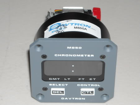
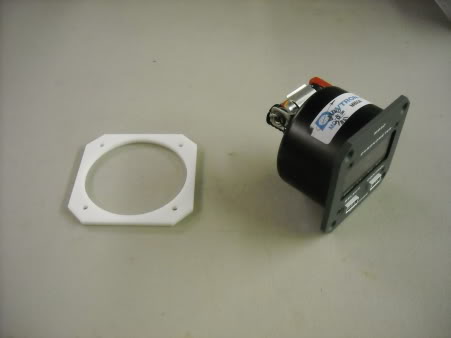
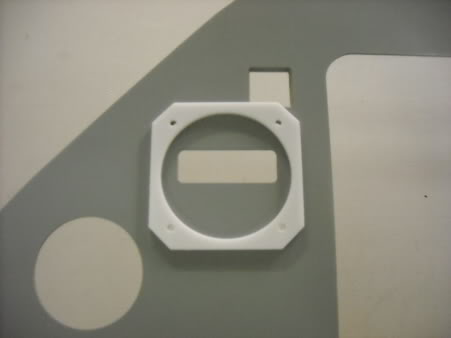
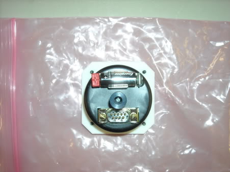
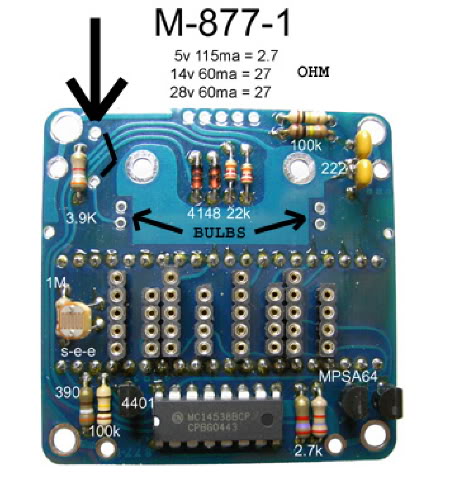
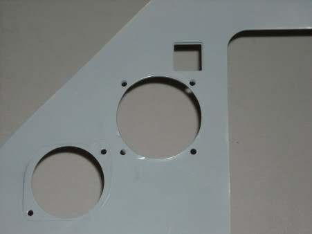
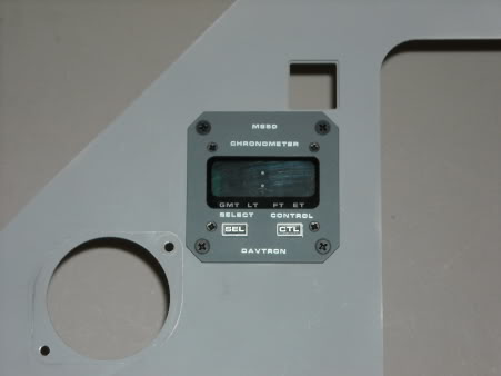
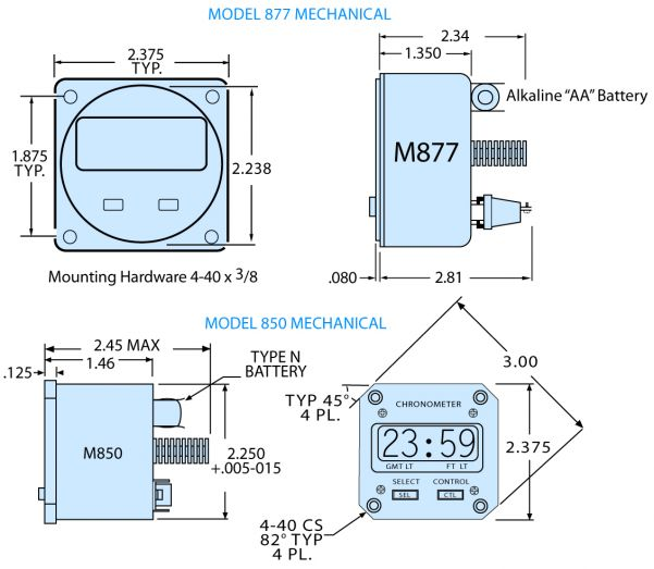
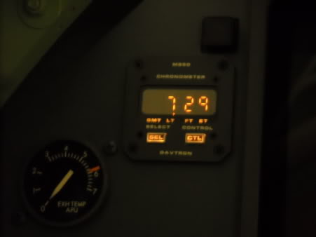
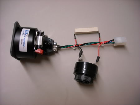
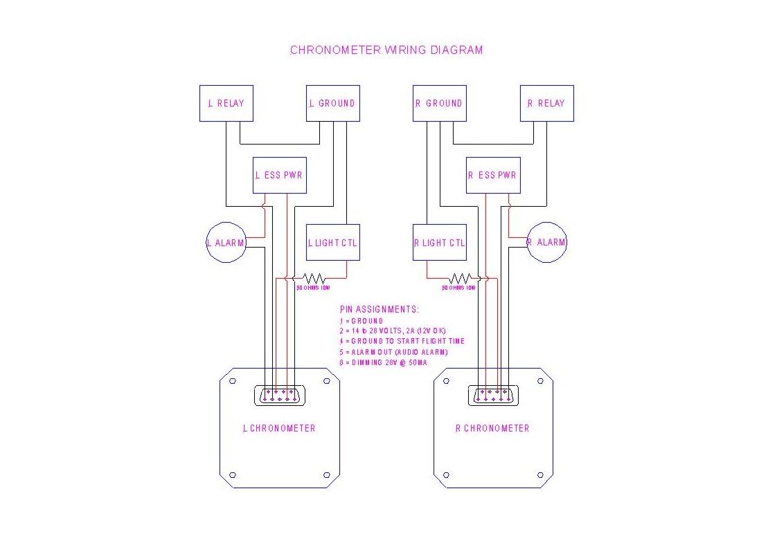
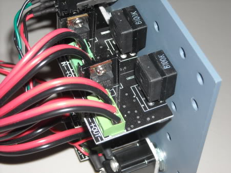
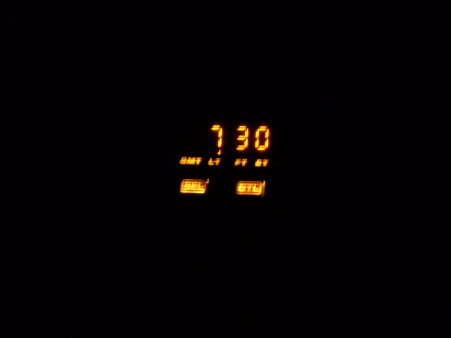
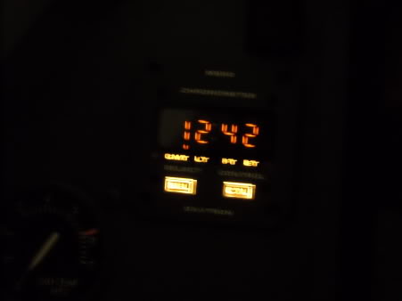
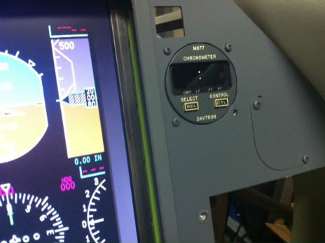
![]()
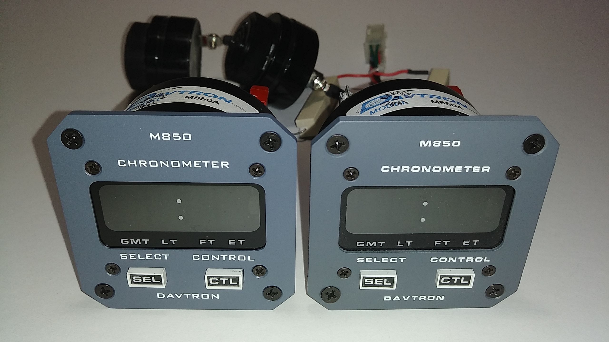
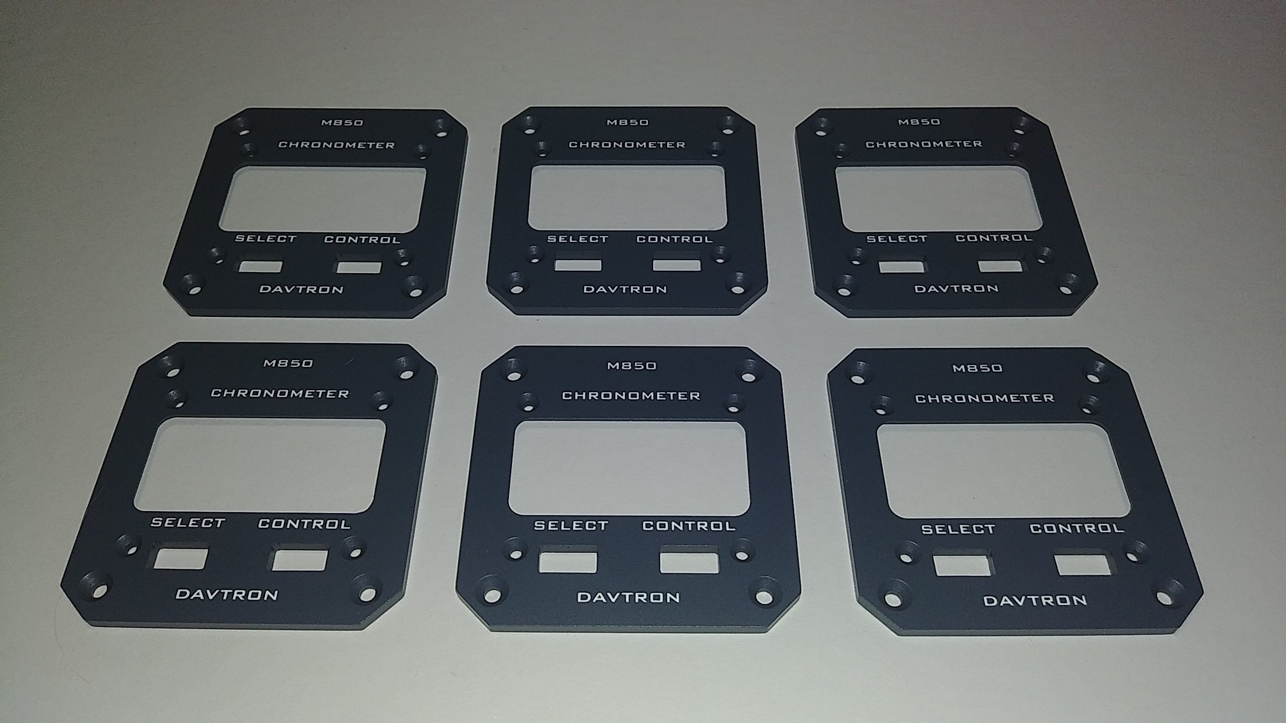
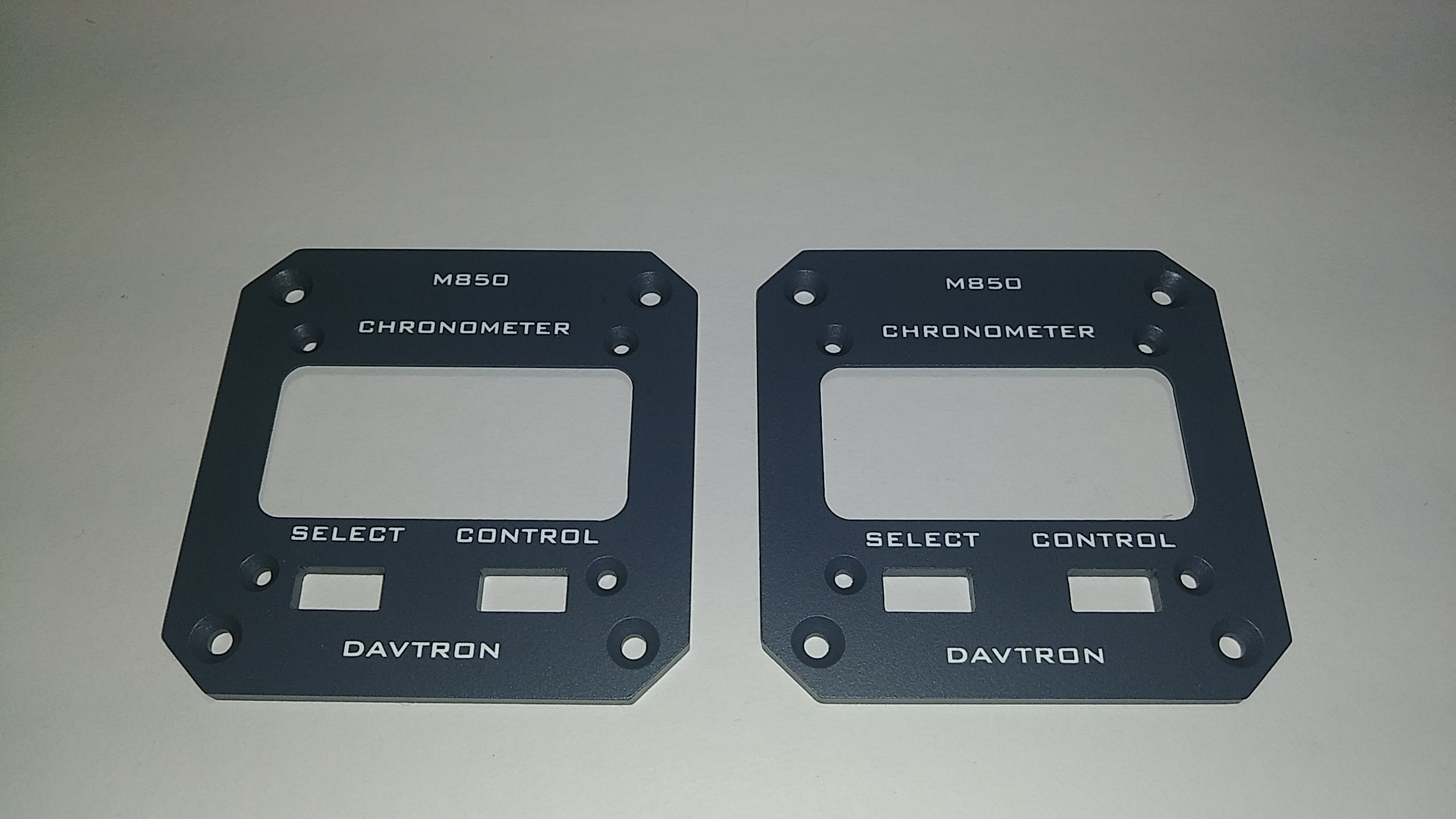
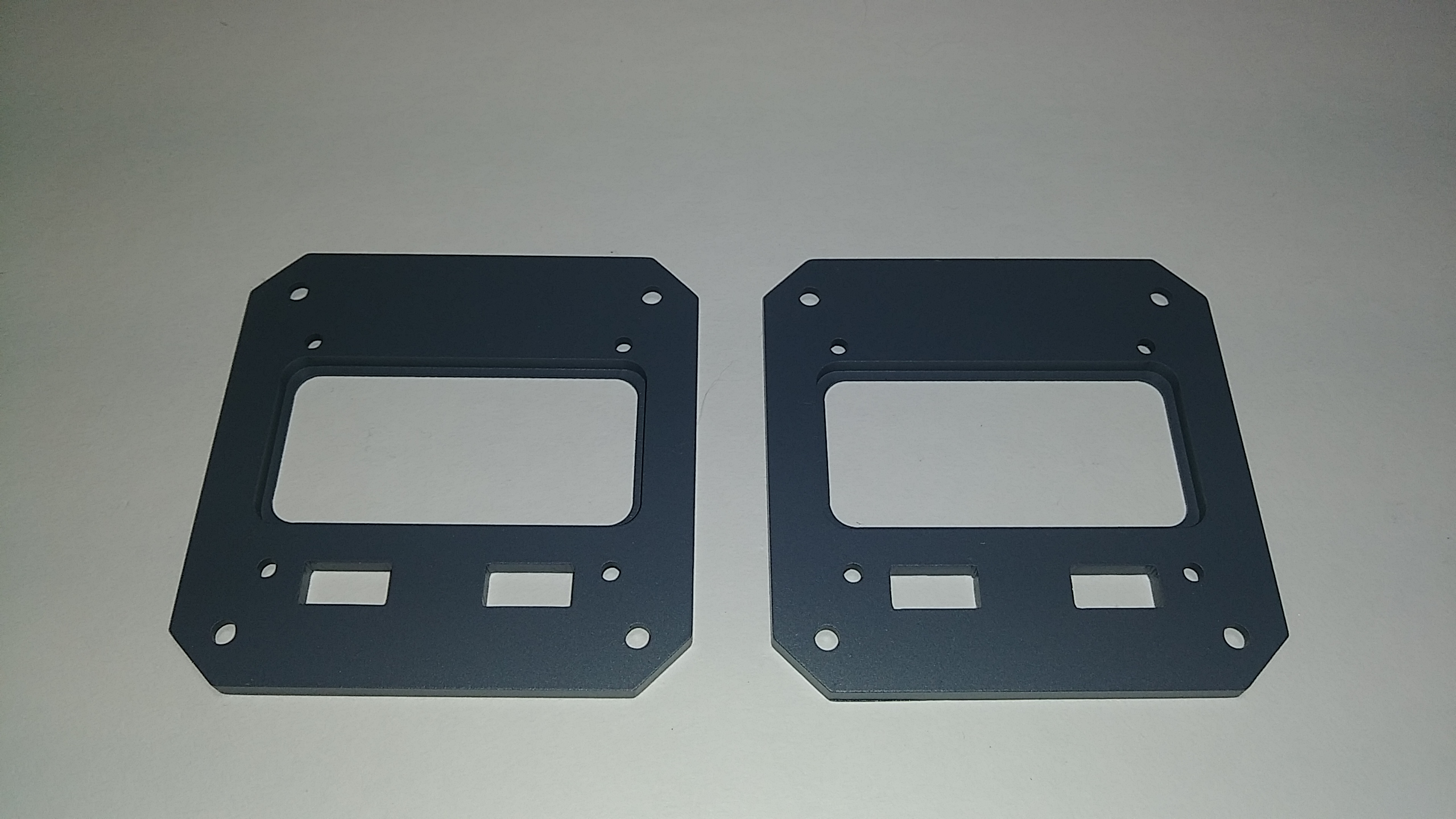
![]()
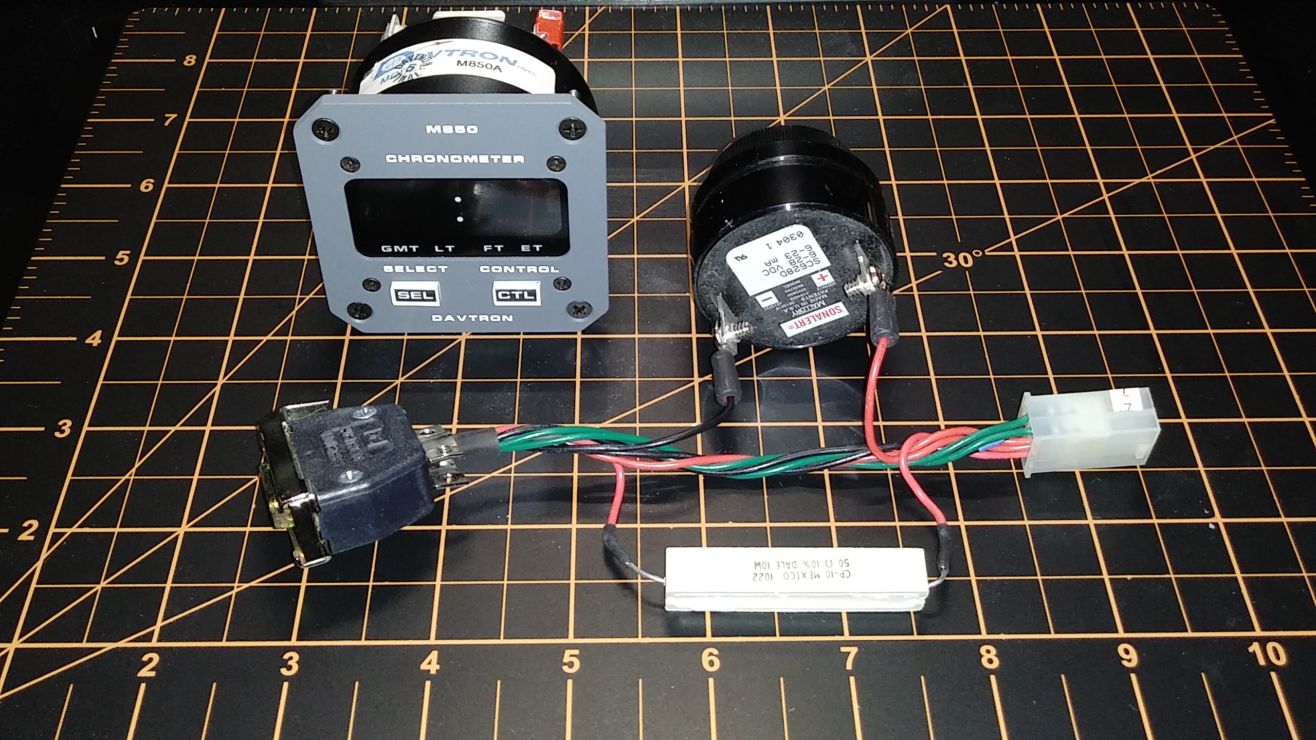
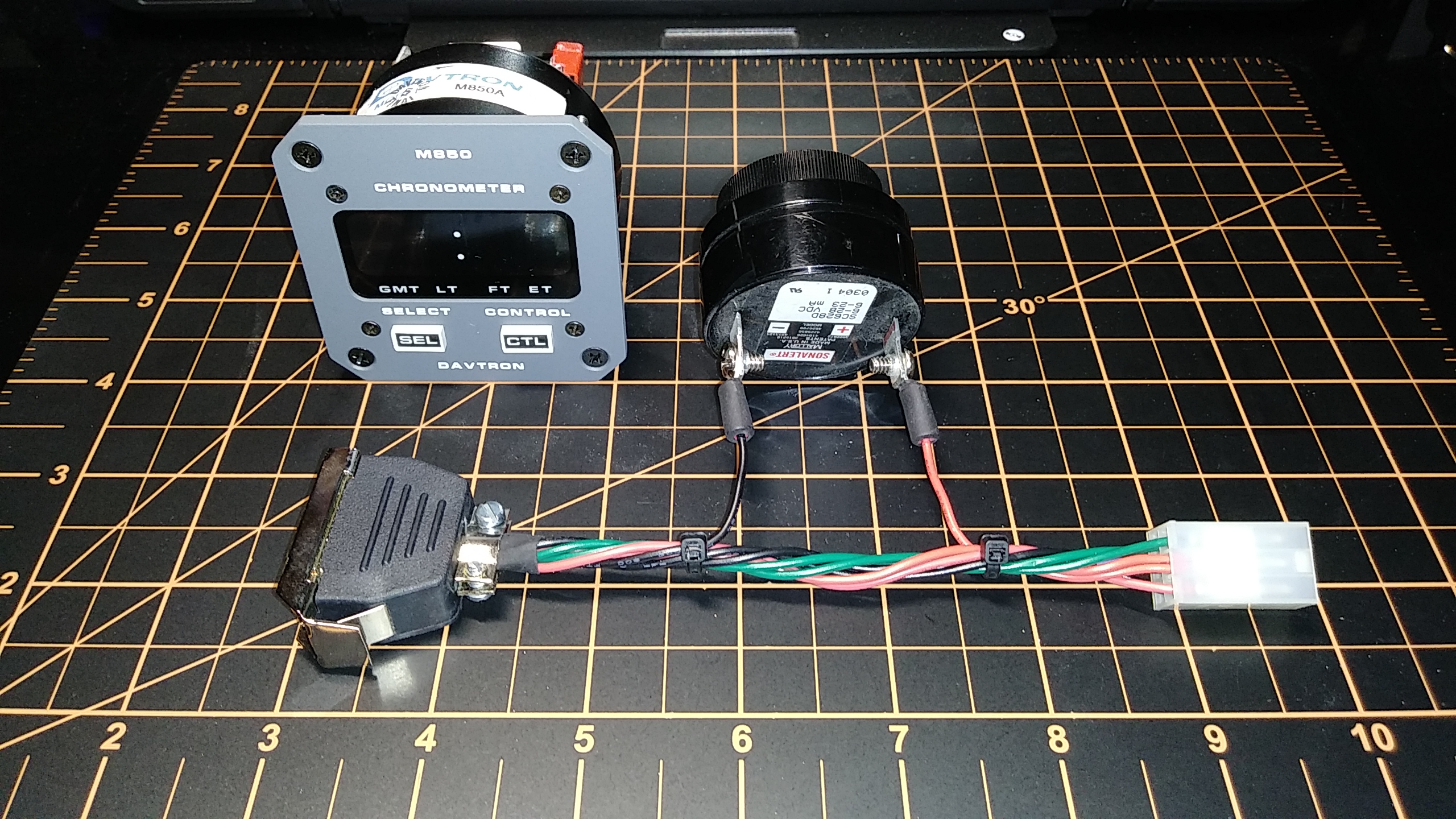
![]()
![]()
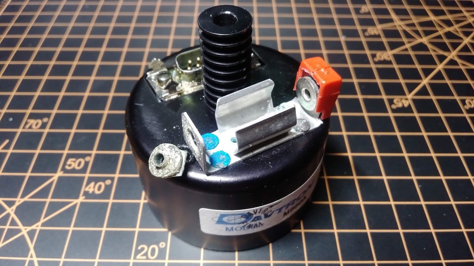
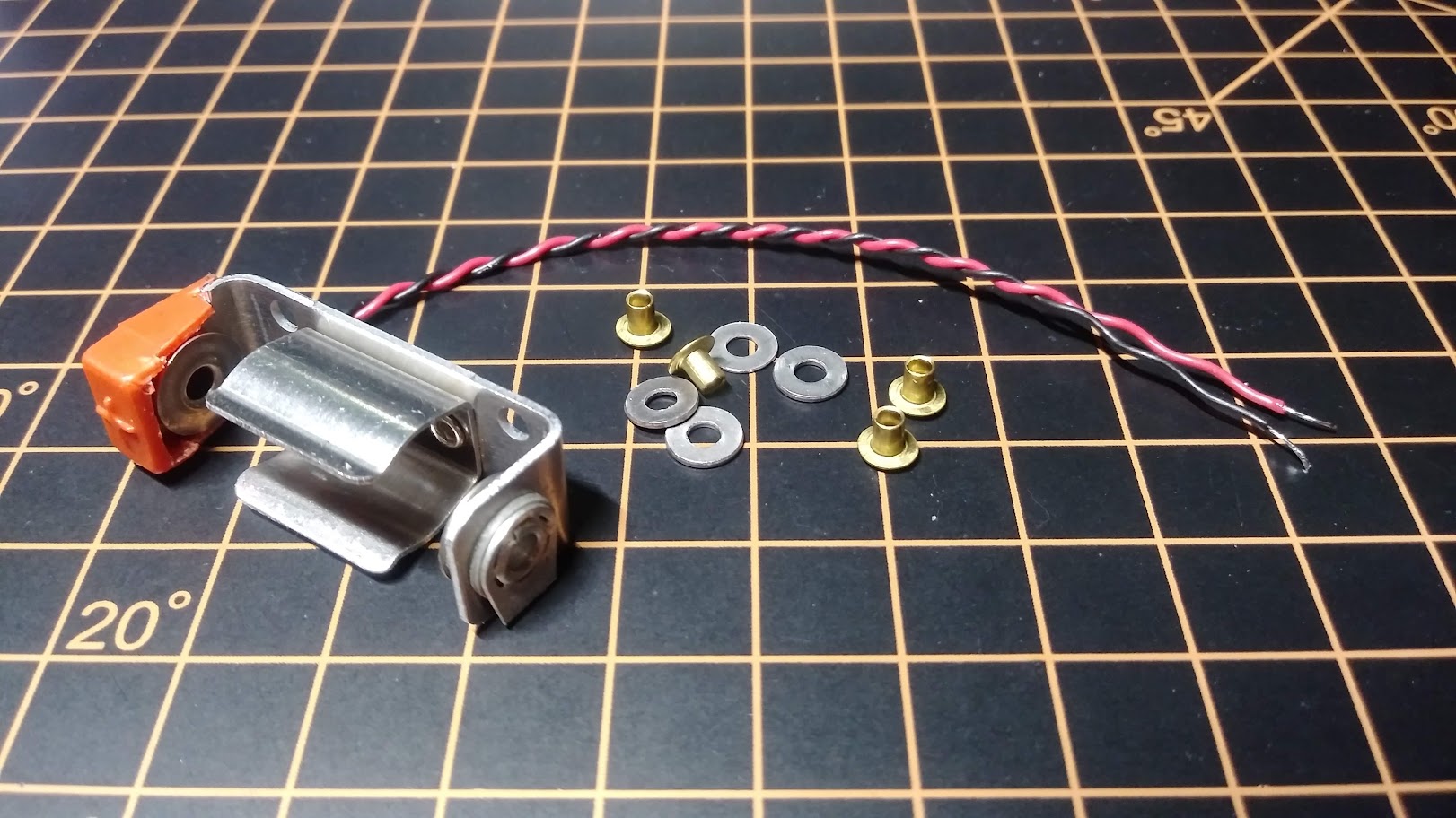
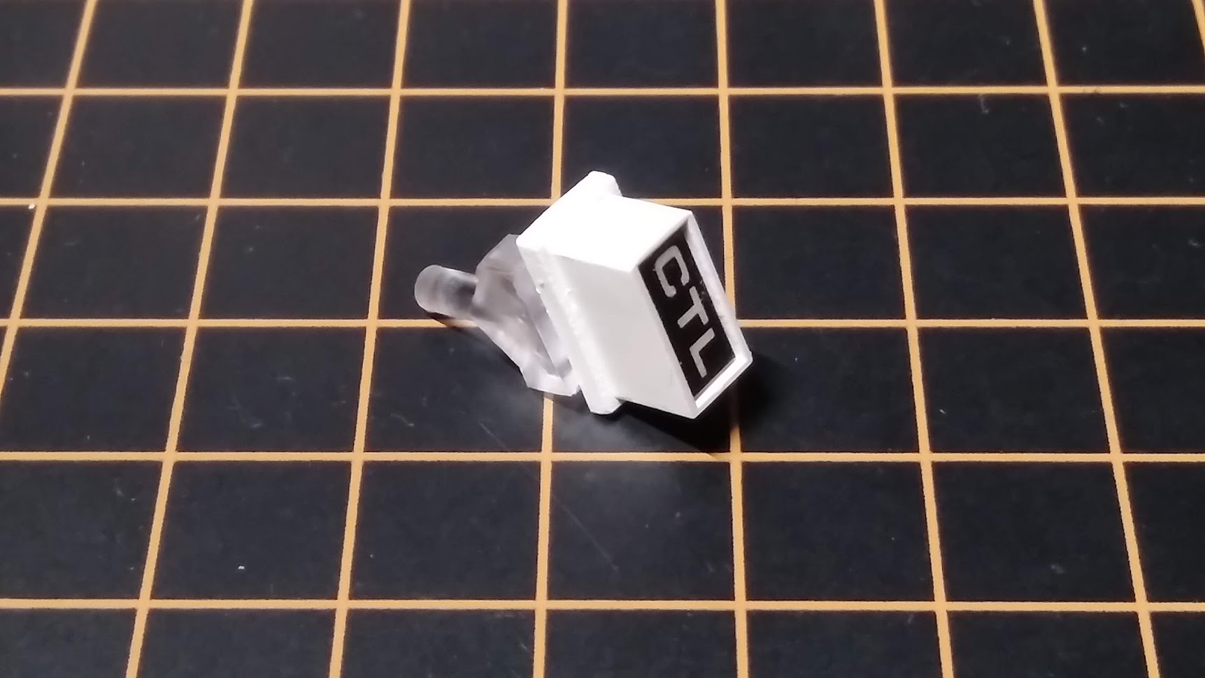
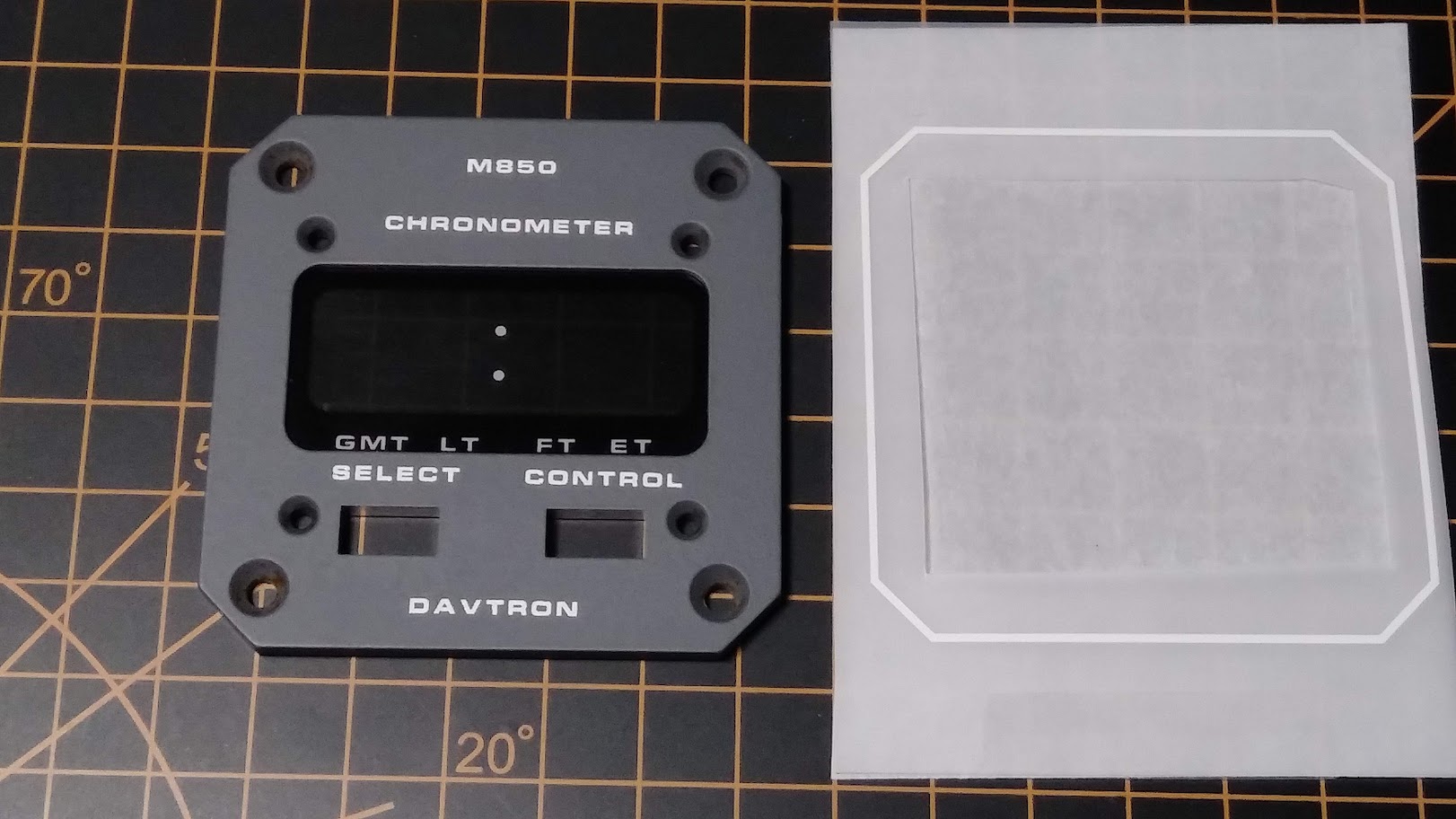
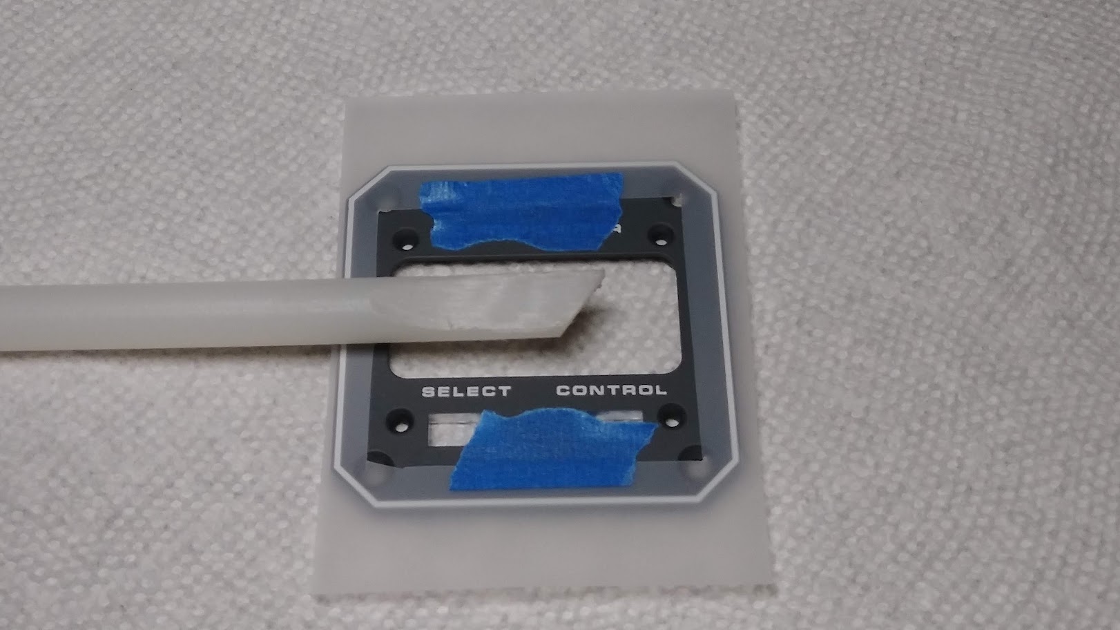
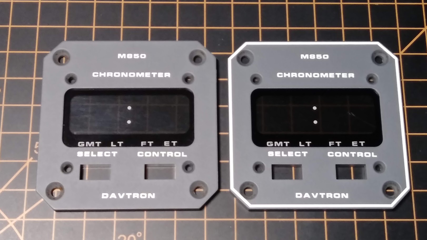
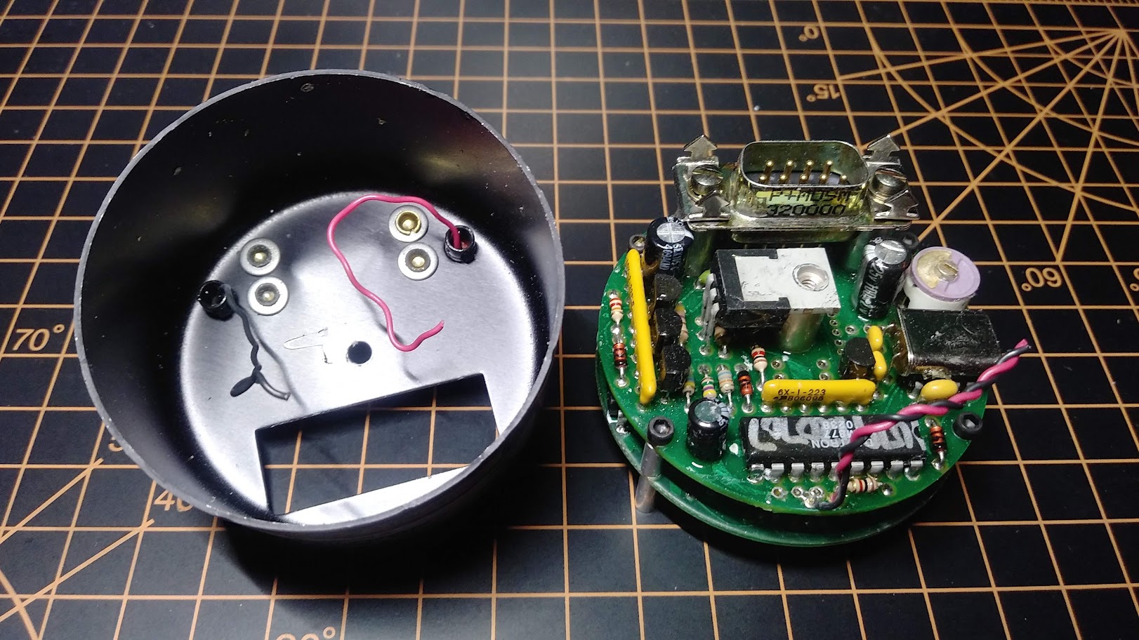
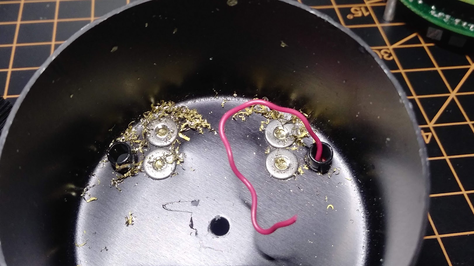
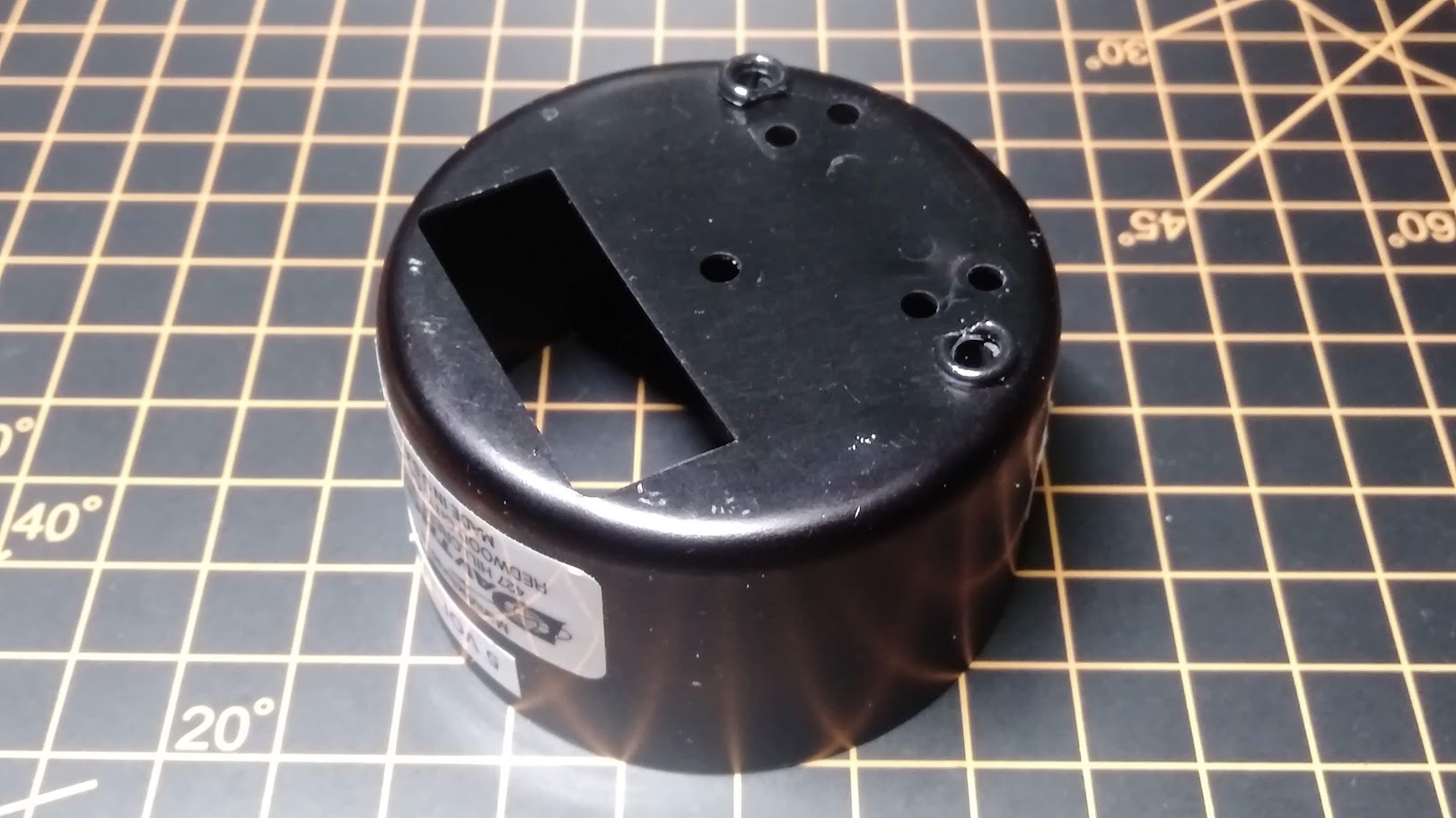
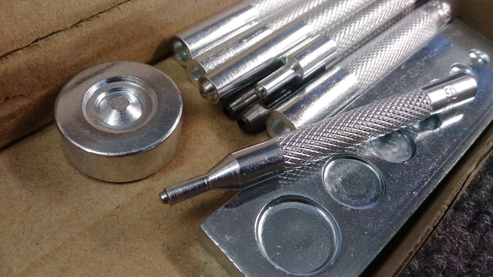
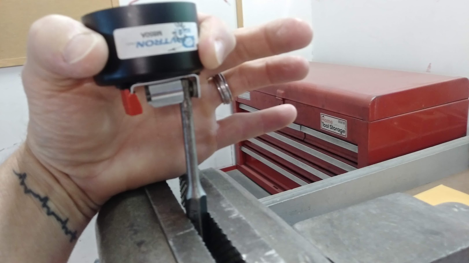
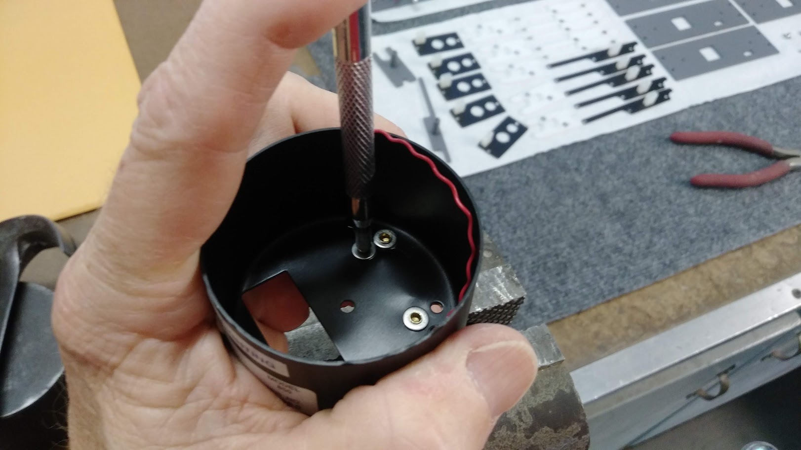
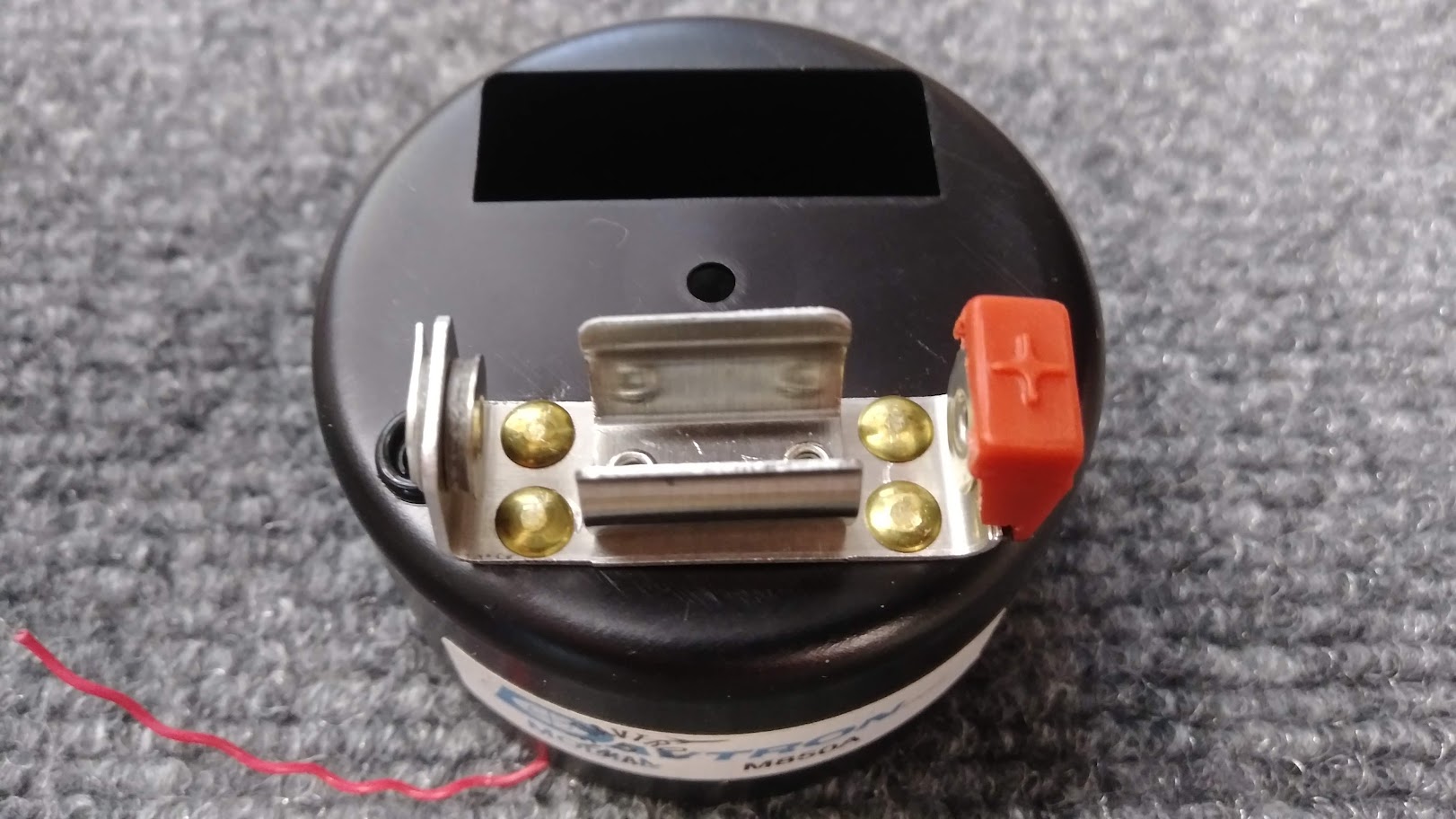
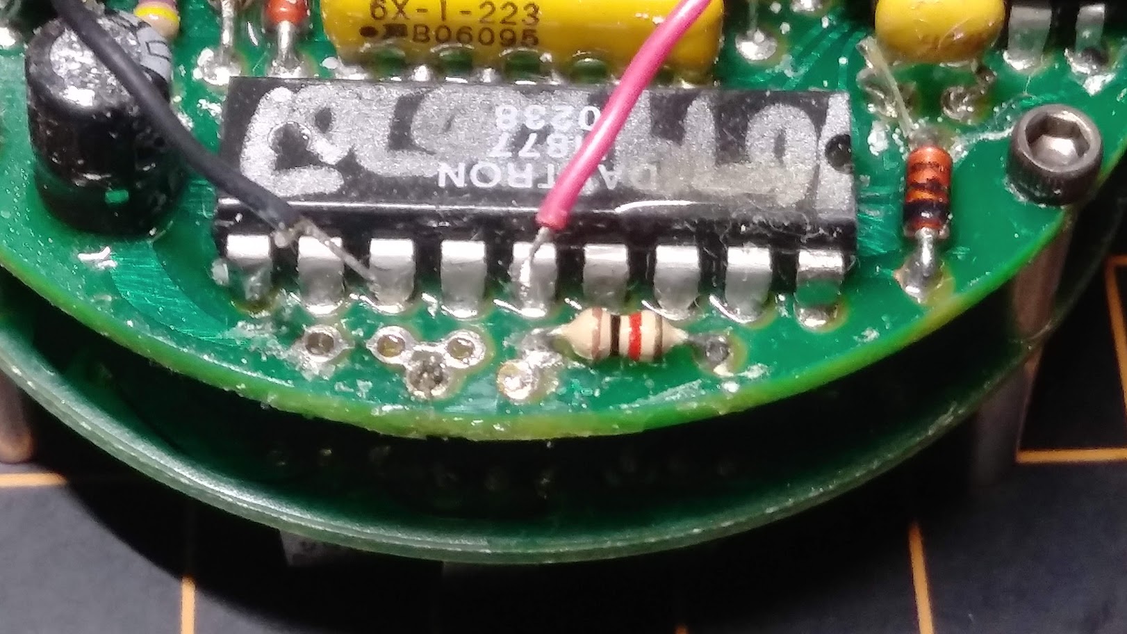
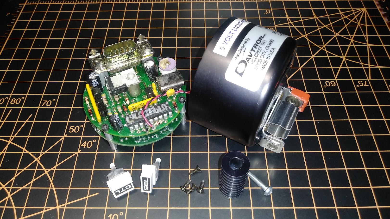
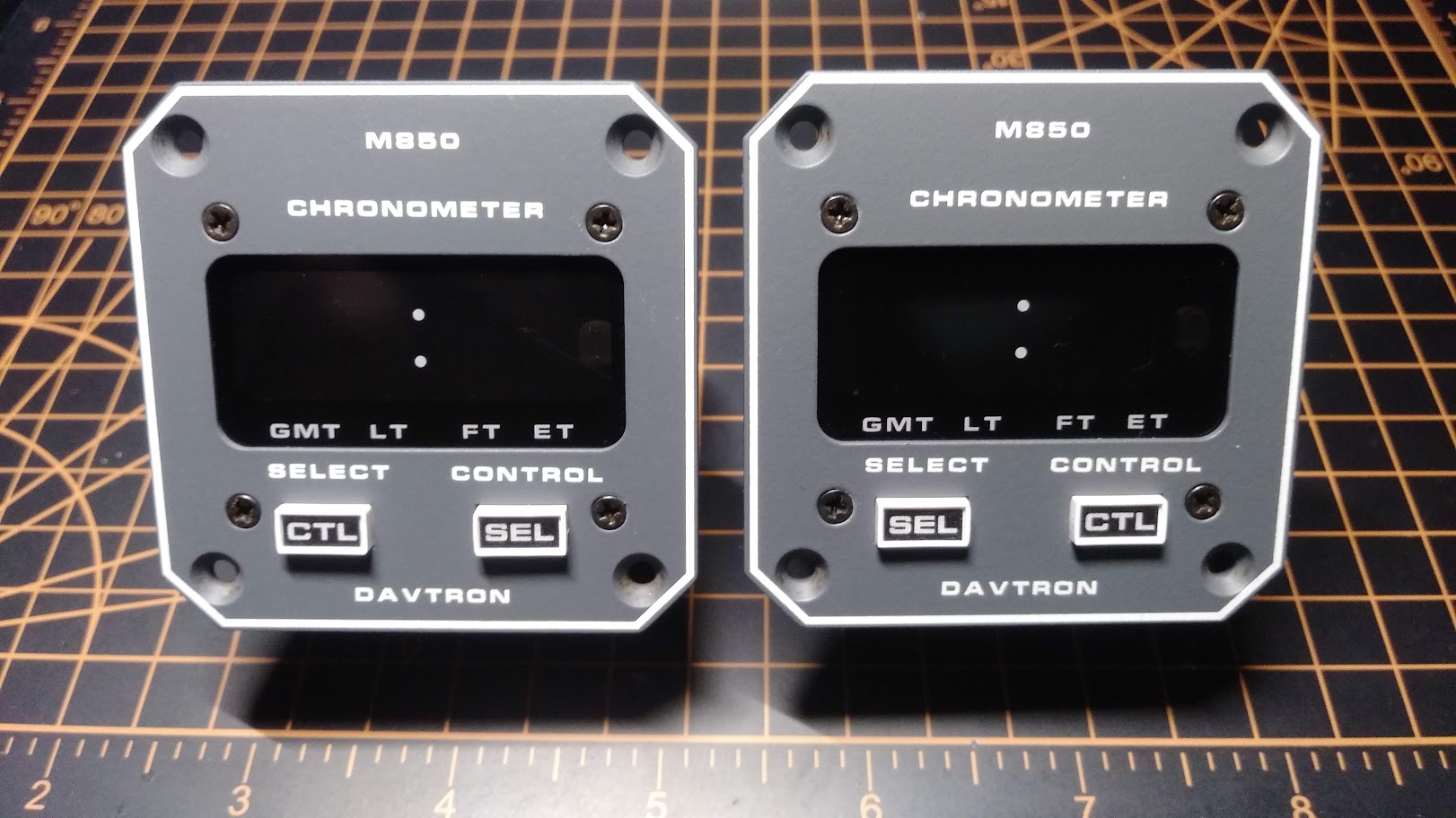
![]()
There is quite a price difference i see.
I also still need to get some transfers for my shell.
There is quite a price difference i see.
I also still need to get some transfers for my shell.![]()
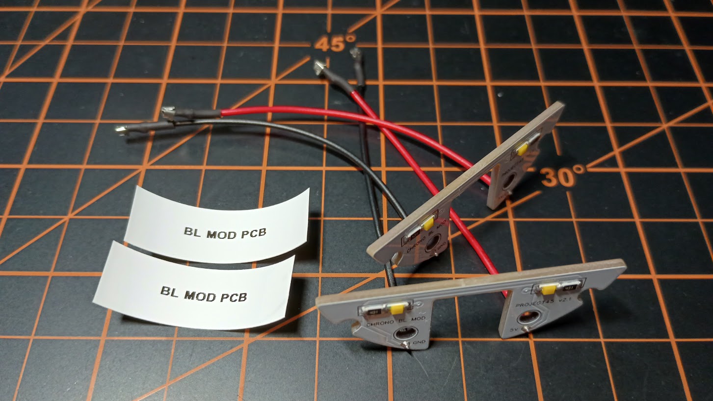
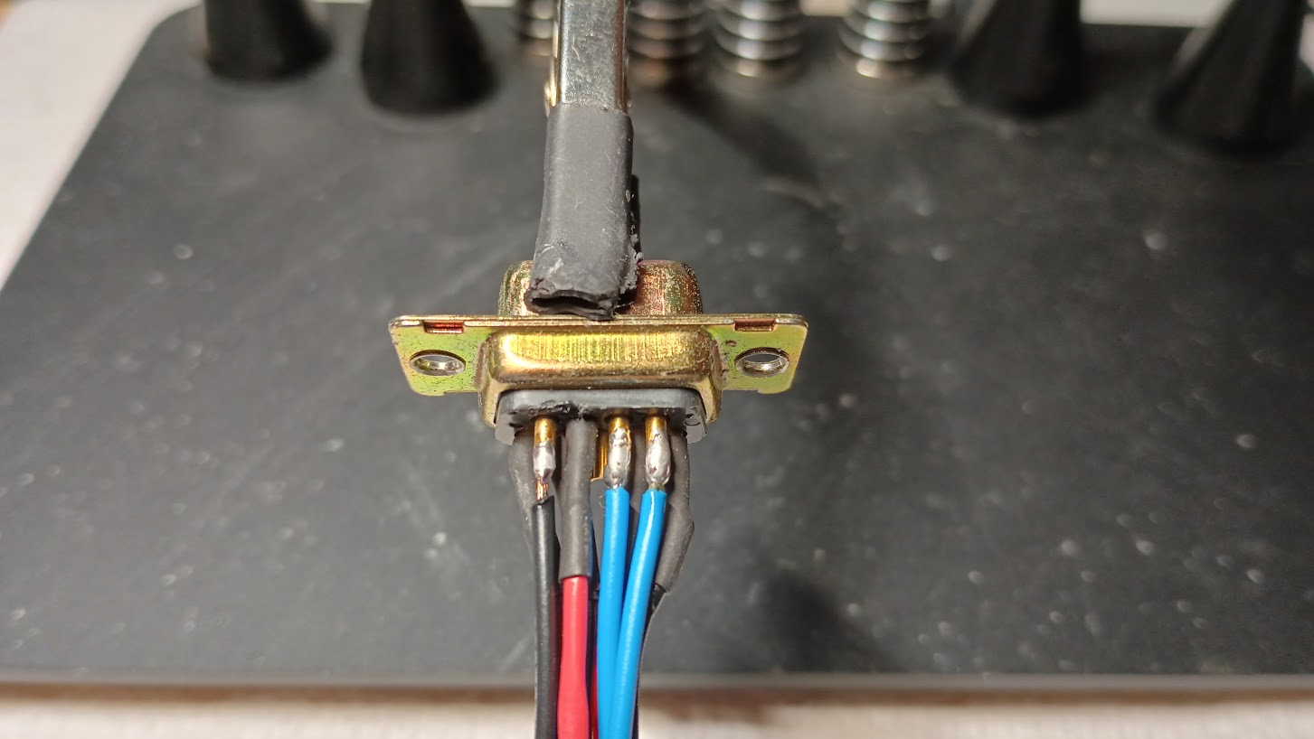
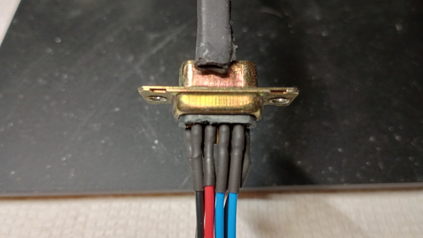
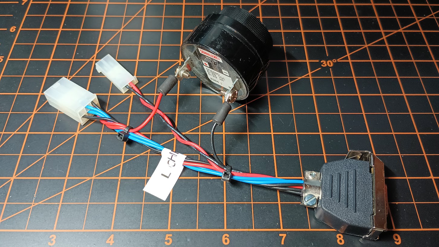
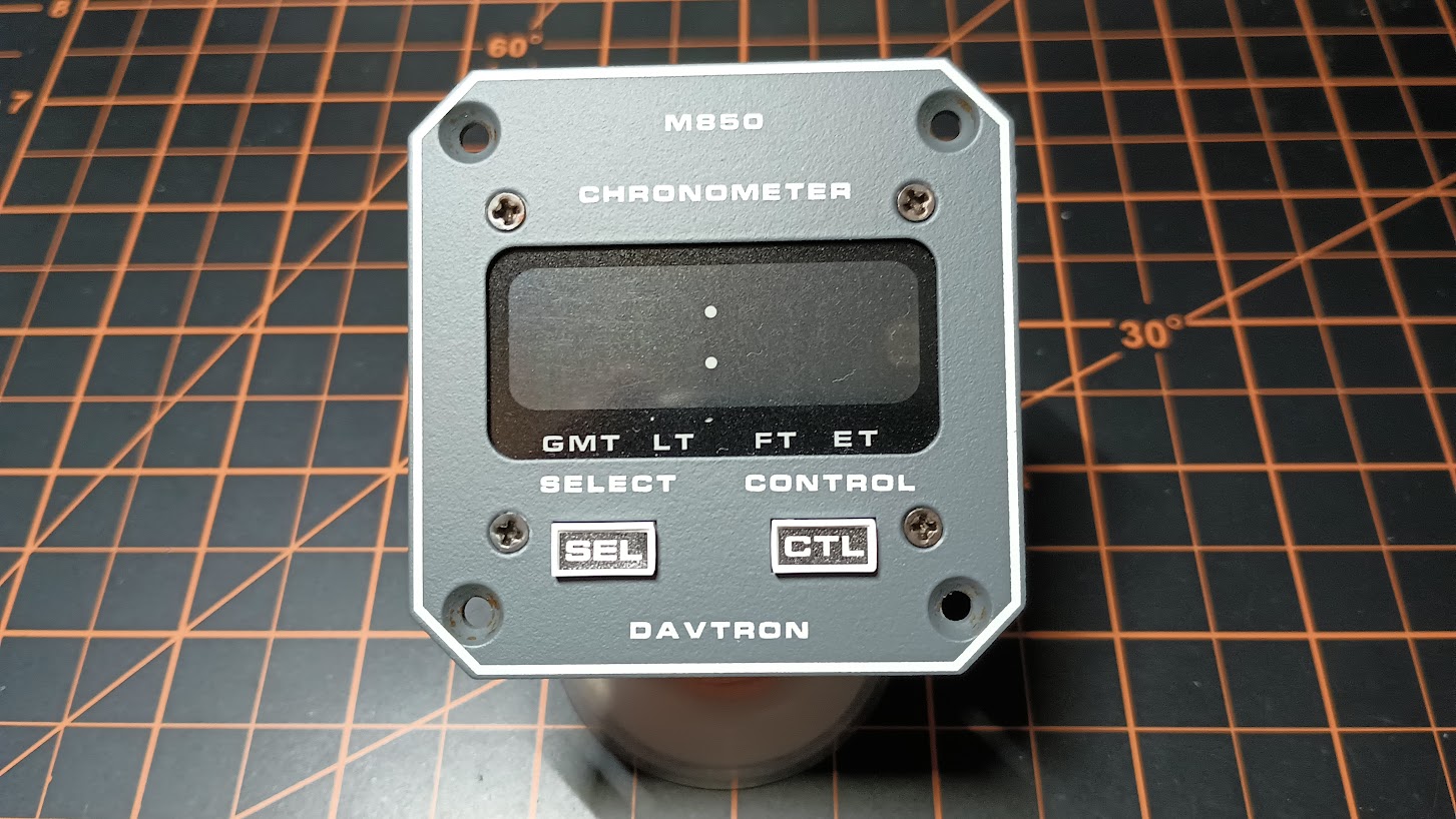
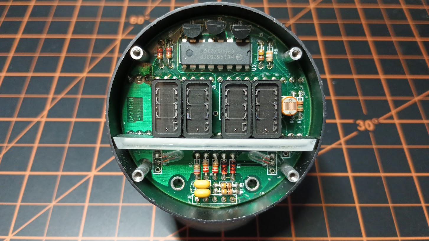
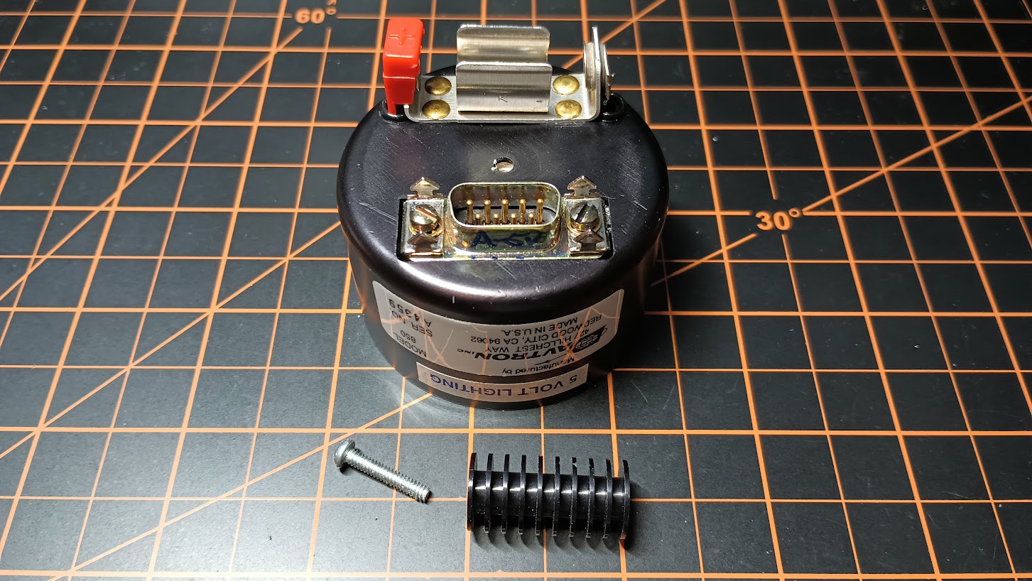
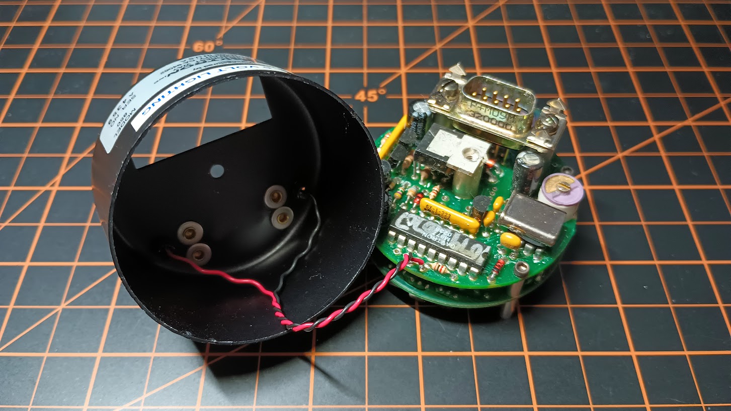
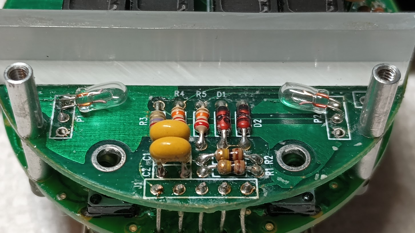
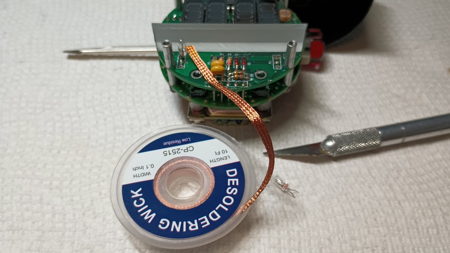
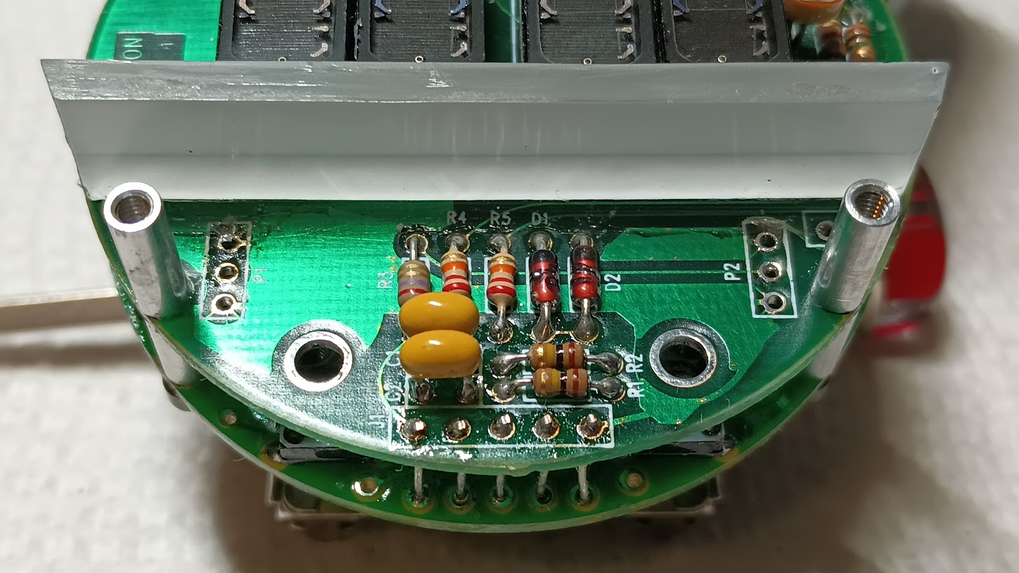
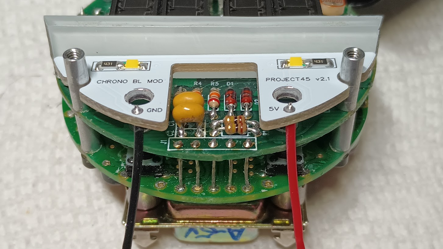
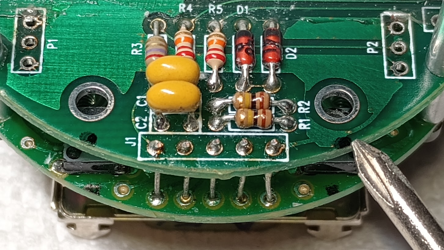
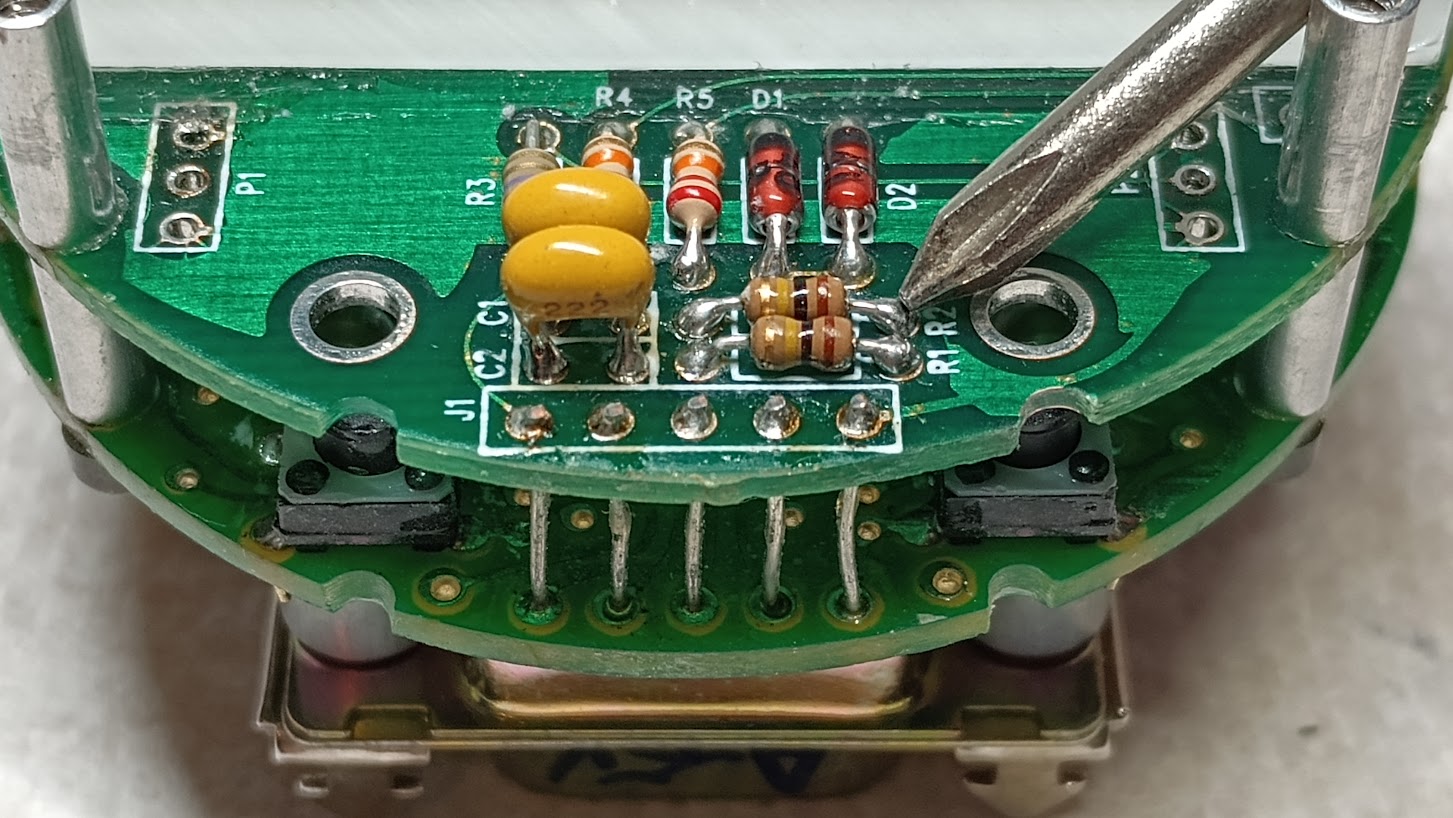
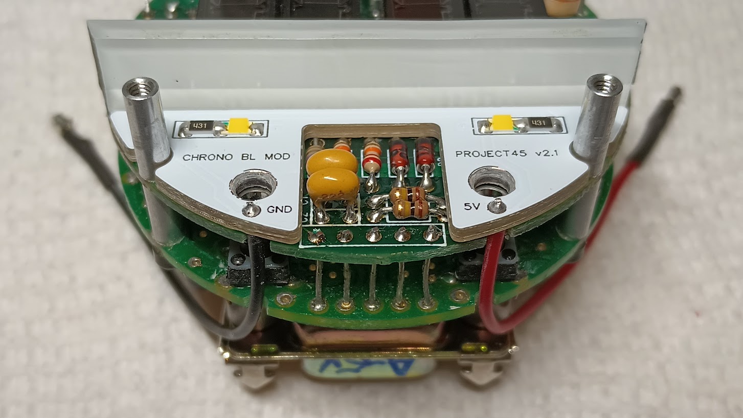
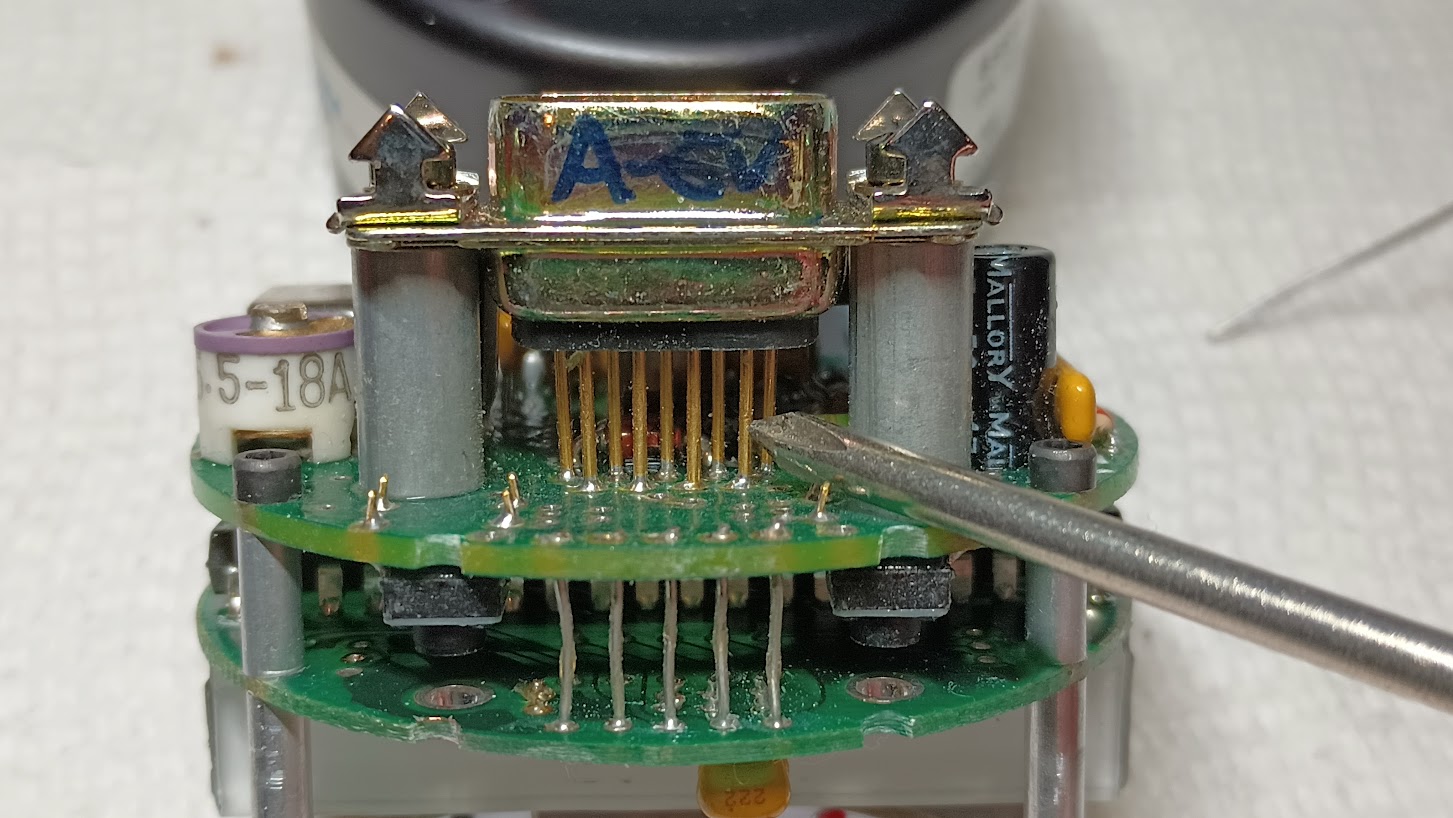
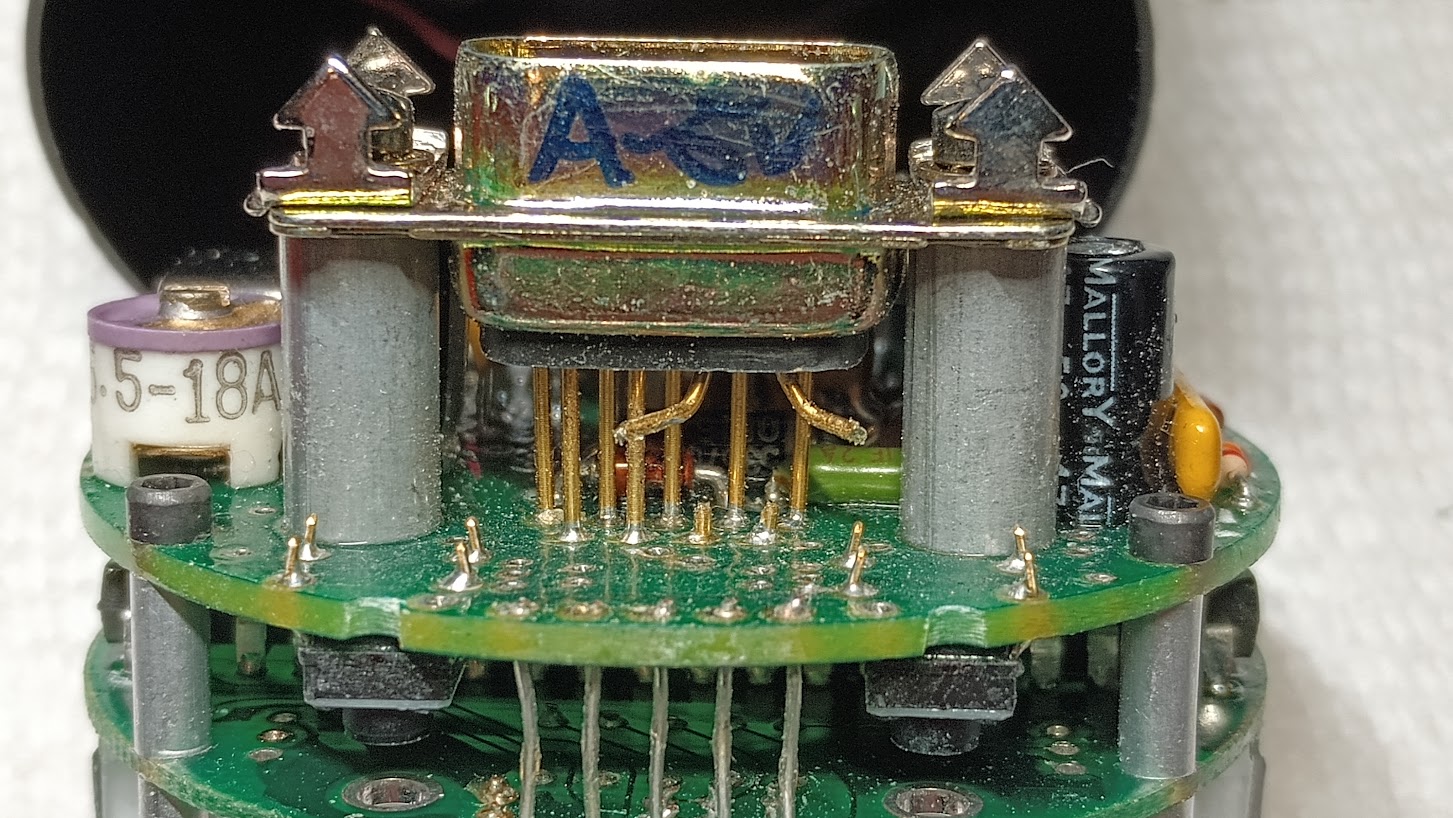
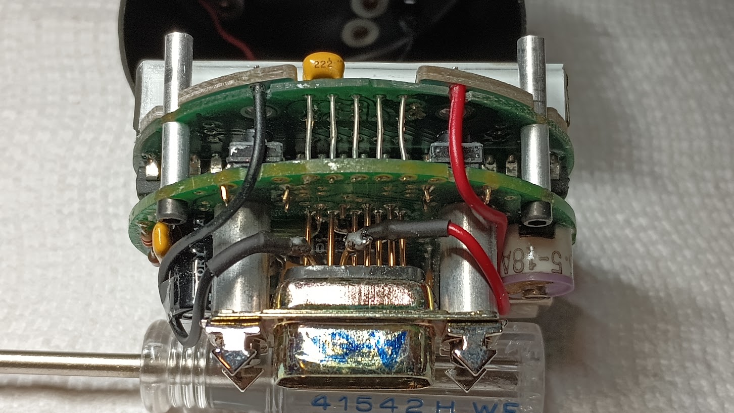
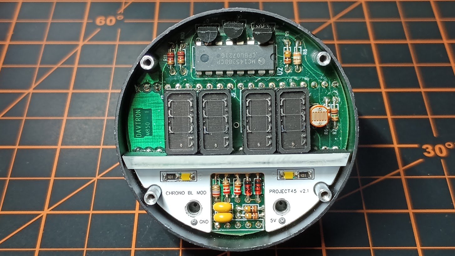
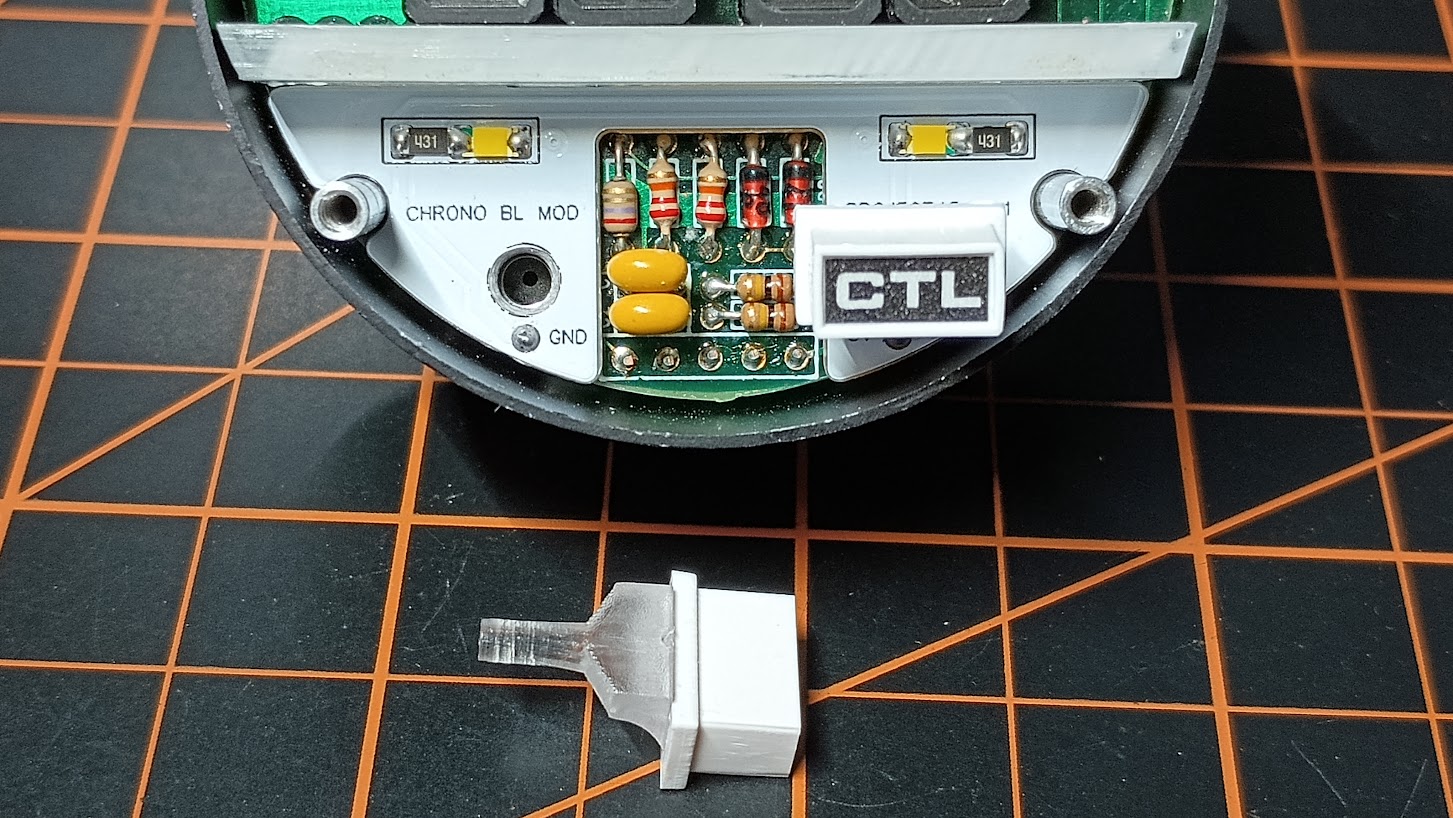
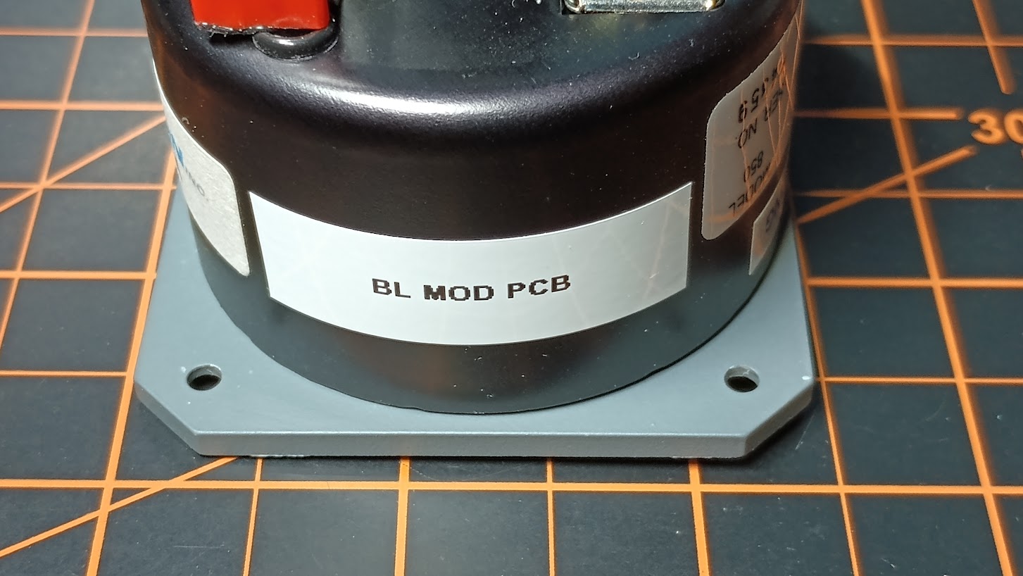
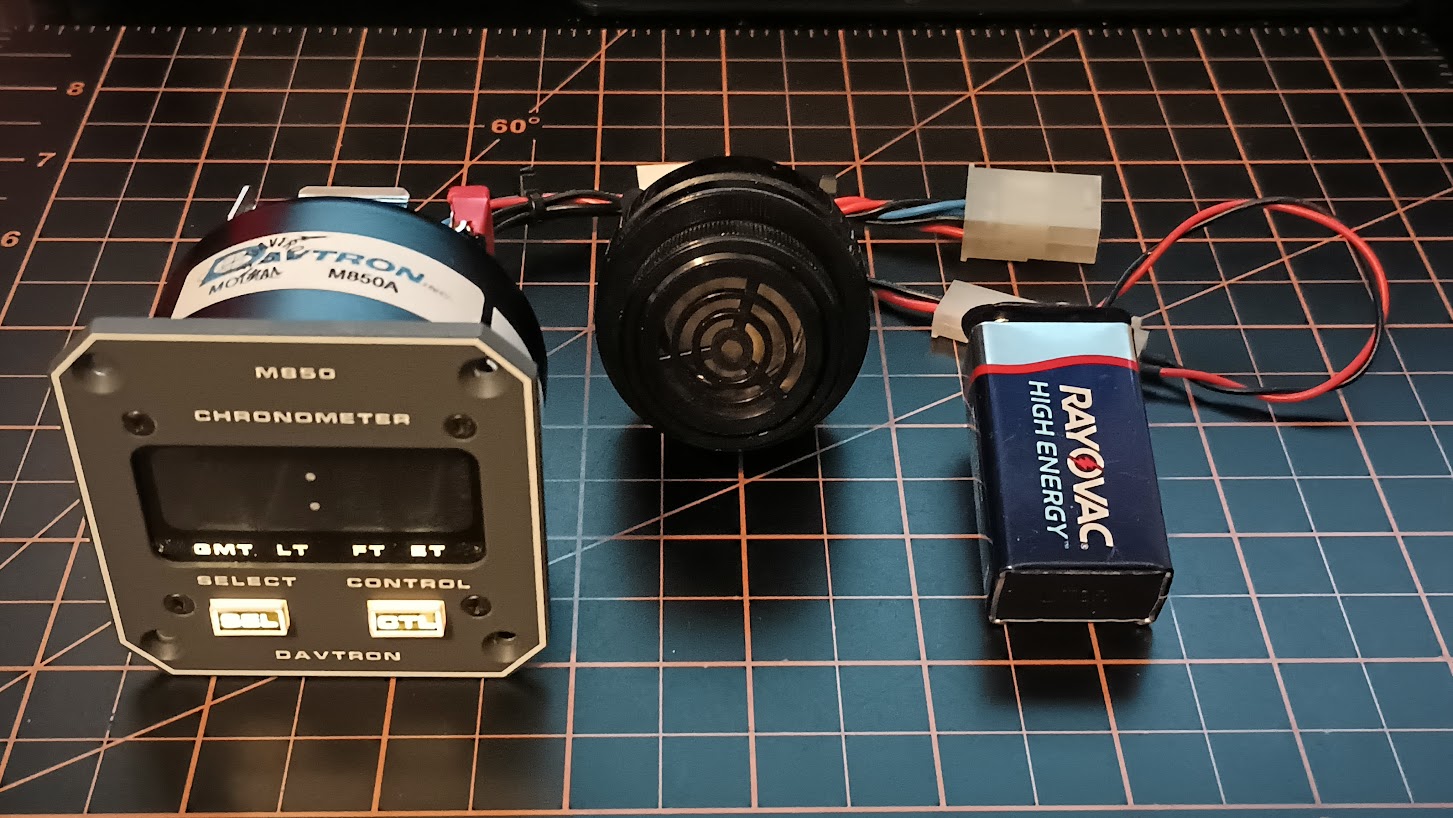
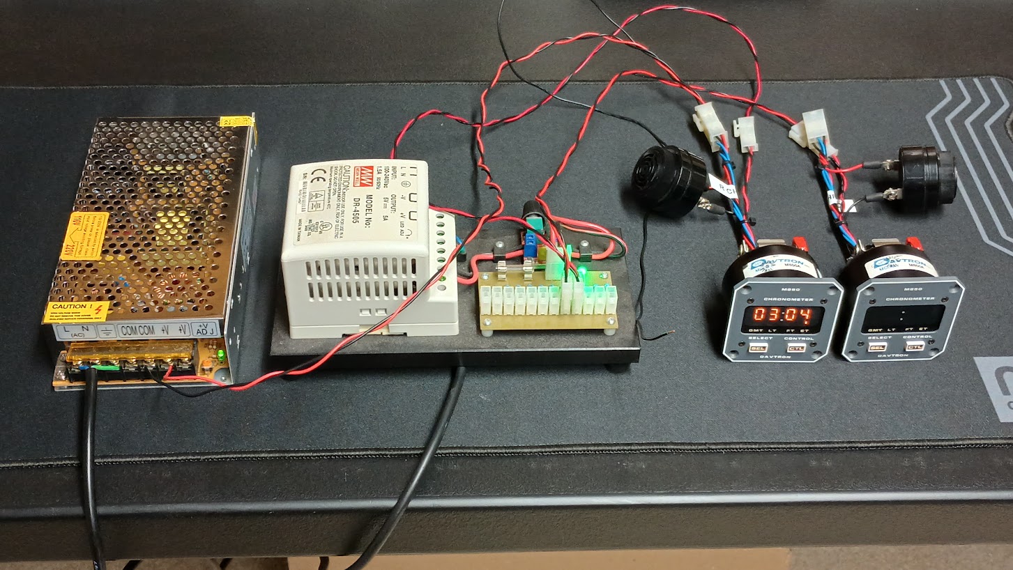
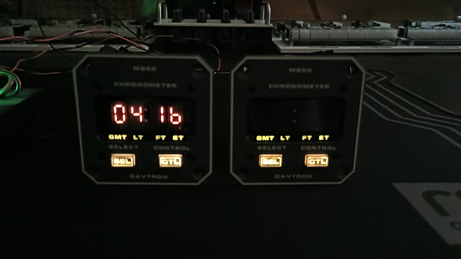
2017-10-10