


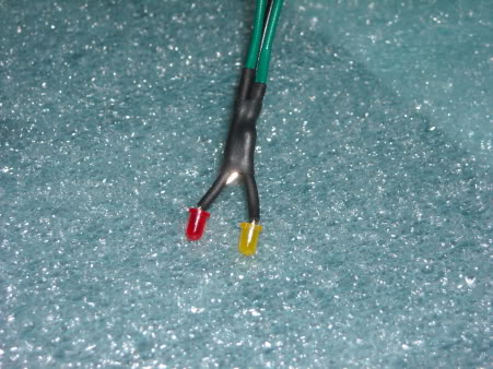
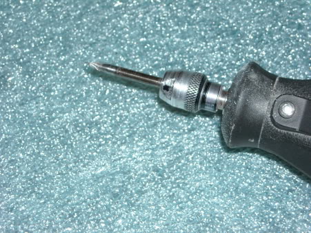
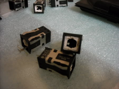
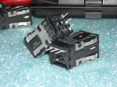
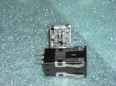
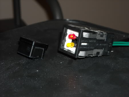
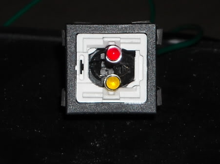
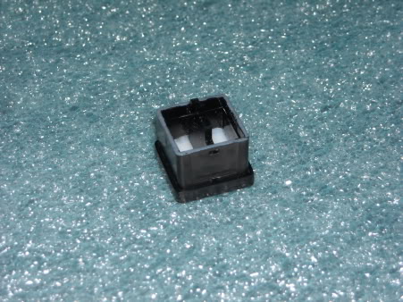
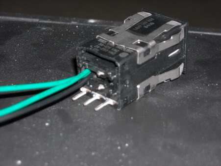
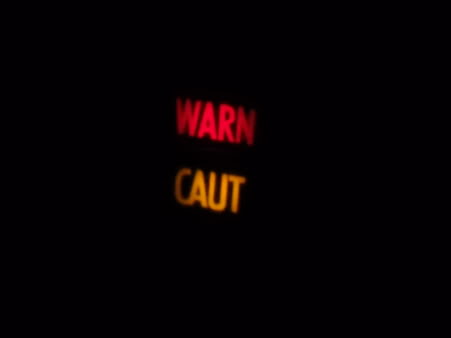
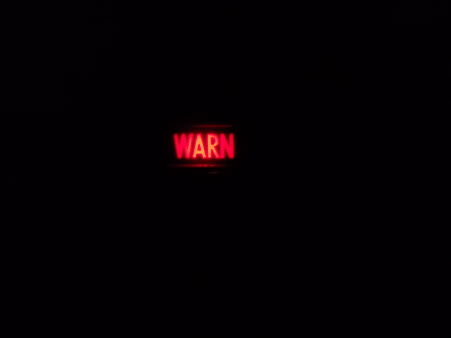
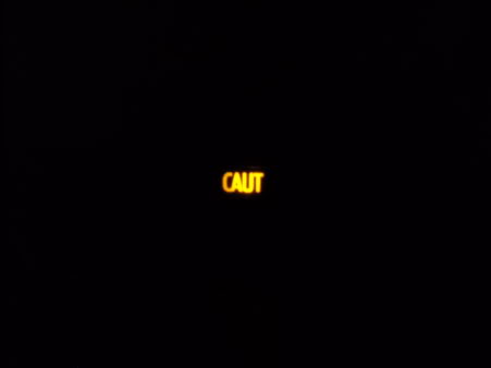
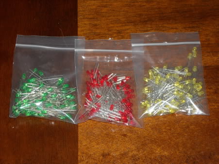
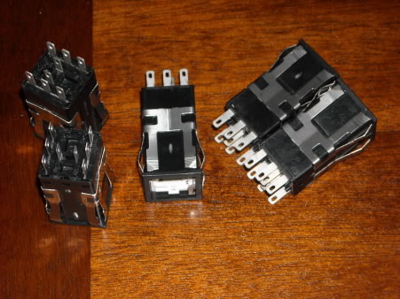
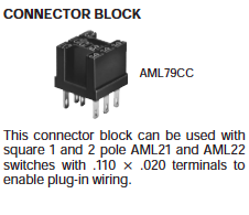
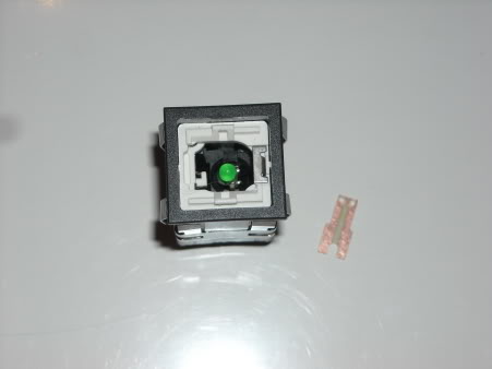
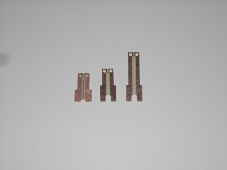
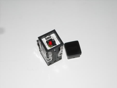
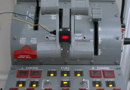
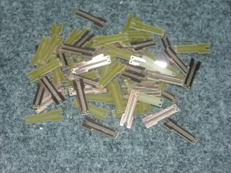
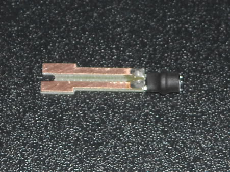
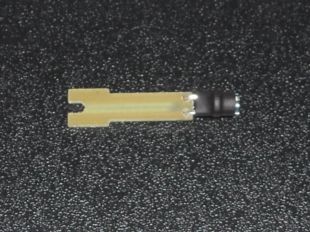
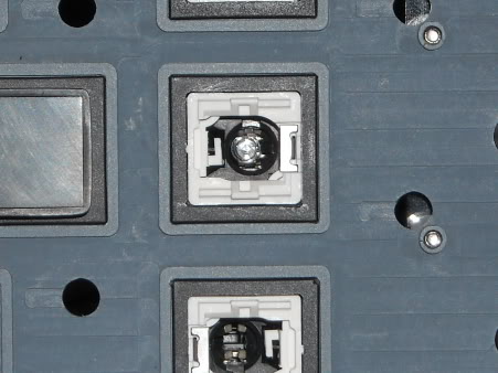
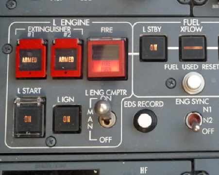
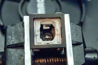
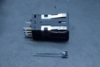
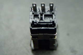
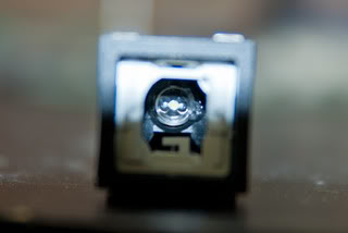
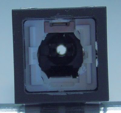
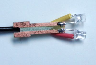
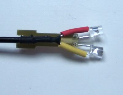
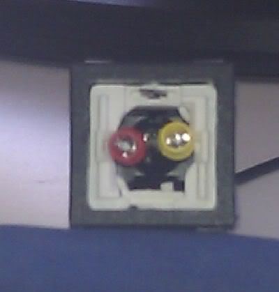
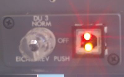
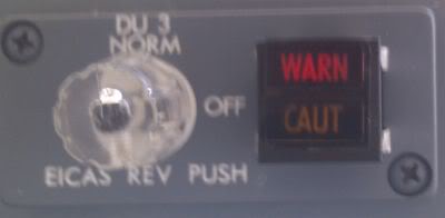
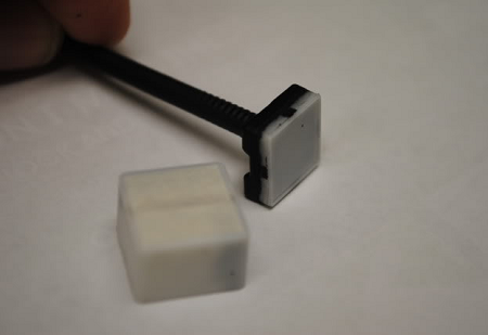
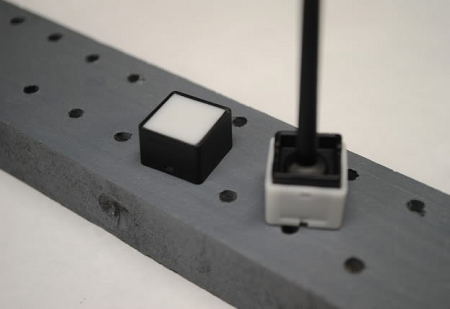
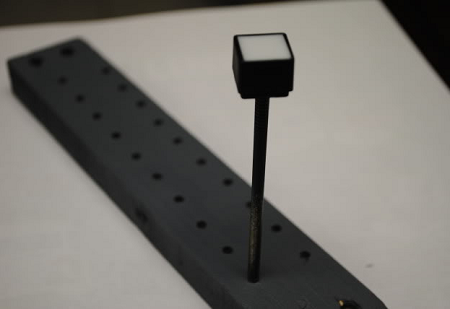
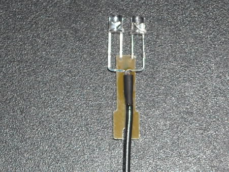
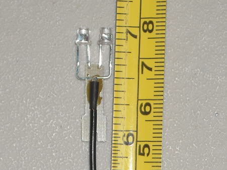
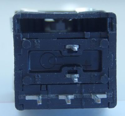
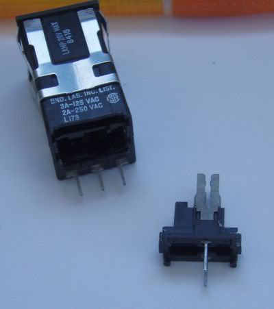
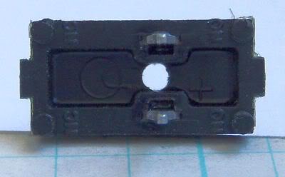
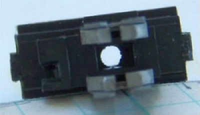
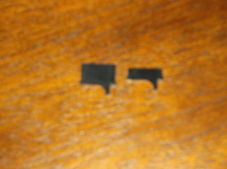
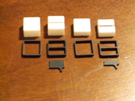
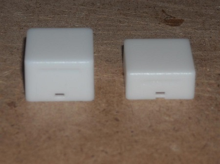
(Original thread started on 03-12-11 by Ron Rollo) The objective here is to take a single pole ON/OFF AML21 that has a single incandescent bulb slot and turn it into a momentary switch with dual LED inside it with a light divider. Or in other words, trying to cram 10 pounds of crap into a 5 pound sack. A little history. Early on, Eric and I decided that the AML21 would be the best fit for our L45 sims. We could get this switch for about $2.50 each, a real bargain compared to the real Chromolux 389 switches if I recall are about $80 each, or more! But we always have known that in order for them to work as we intended them to, we would need to find a way to get the few double legend switches to work right. Well thanks to a few guys for taking me up on package #3 of the REV panels, it kinda forced me to come up with a solution to this long time problem we all face, at least those using the AML's. So here we go! First, I took two LED's and wired the grounds together. This way I only have three wires that will be coming out of the backside of the AML. It also insures that the two LEDs will remain level to each other and side by side. I used shrink wrap to protect the positive leads and then another piece that helps hold it all together: If you don't have a Dremel tool, get one. You'll also need a small bit that will reach a little deeper: Shape out two small notches at the top and bottom of the white sliding carriage to make a little extra room for the two 3mm LEDs. Every bit of space counts especially when trying to pack two LEDs into the AML that was only intended for one: One thing you might as well do is remove the two PCB prongs for the bulb in the middle: One thing you might as well do is remove the two PCB prongs for the bulb in the middle: With a drill bit, drill a hole as indicated in this picture. Drilling in this spot will insure you don't hit anything that you DO NEED! By the way, if you need to make any of your AML21's a double pole switch for any reason, pull the triple prong PCB single pole plug out of a sacrificial AML21. Then slide it into the empty slot on the left. Wah la! Double pole: Now, it kinda feels like giving the AML a root canal! You will want to drill away some of the plastic material to the side wall of the bulb carriage. The best way to describe the shape of the hole your creating is a funnel, or twister. It is going to be round and wider at the top and get narrower the deeper you go. I found for some reason, it kinda happens automatically, so don't worry too much about this. But the idea is to make a wedge. When we thread the wires into the AML body, the shrink wrap will stop the LED assembly from going all the way down. Here the LED assembly is installed: Because the wires are wedged in the bottom of the AML housing, it holds the LEDs at a certain position. You want to make sure they are deep enough into the AML so that the cap top does not hit them. Test fit the cap and make sure they do not hit the cap when pushed. If they do, pull the LED assembly deeper through the AML housing. You will also find that you will need to bend the LED wires into a slight curve to get it to sit right. Trial and error. Below you can see how the slight notches near the LEDs play into the design. There is just enough room between the two LED's for the light divider: Okay, this is the part that I was worried about. Light bleeding from one LED chamber to the next. But to my pleasant surprise, there was none! I designed what I call a light divider that comes with the lens kit and it works like a champ. However, with my personal project, I am going to use CA glue and seal the light divider in place and any small cracks that light can seep through form one side to the other. Then I'll hit the seems with a little black modeling paint. In the photos further down in this thread, there is no CA glue or modeling paint applied. Here is a photo of the AML cap sitting upside down with the frame and the light divider: Here you can see the wires coming through the back side of the AML body: This is the modified double AML21 all lit up. No light bleed: WARN by itself. No light bleed into the CAUT area: CAUT by itself. And no light bleed into the WARN area: And the modified AML in action simulating a light test on the REV panel: So far I have done two of these. Now that I know what I am doing, I would say it is going to take about 30 to 45 minutes to do each of these. I think we have 13 in total. (Posted by Mark L. on 03-13-11) Looks great Ron, way to work the problem. As always, I'll ask, sourcing for the LED's? Since you have the color, intensity etc that seems to work, would be nice to replicate exactly. Total length from bottom of the LED to the end of where the shrink wrap that holds both together? It will rule out fighting issues with that. (Posted by Ron Rollo on 03-14-11) The red and yellow LEDs that I am using were left over from a FDS K-1 switch package that I ordered three years ago. Until just a few days ago, I have been under the impression that we need 5v LEDs so that we could wire them into our FDS SYS boards. Have you ever tried to buy a 5volt LED? So I measured the voltage coming out of my "5 volts" terminal on my interface card and it is 3.5 to 3.7volts. I have some LEDs ordered but they are 2.7volt LEDs. I will let you know how they turn out. I am also placing an order with PC, so I will try to find out exactly what he is using because they look great! As soon as I find out one way or the other, I will let you all know. (Posted by Mark L. on 03-14-11) I'm not sure I've ever heard of a 5v led. Typically this is in the 2.5 to 3.5 volt range, more commonly found right around the 2.7v. This is also why the need for the resistors to drop the voltage and limit the current for the led circuit. Looking forward to what you find out. (Posted by DonnyRay Jones on 03-14-11) You can buy LEDs with a built-in current limiting resistor, but most of the garden variety single LEDs we use are simple diodes. They don't have an internal current limit resistor. So get out that LED spec sheet and find out the maximum forward current and use a resistor that will limit at that current. Sure enough, you can make a 2.7 volt LED produce light without a resistor. But not for long...... (Posted by Mark L. on 03-14-11) Some IOCards depending on design may be able to drive the led without the resistor because they have the current limiter built in already for you. I have a OC card that can drive LED's without the resistor as well. (Posted by Shane Barnes on 03-14-11) You are planning on using the FDS SYS cards and if so you don't need to worry about resistors on the LEDs that you place in the switches going to the SYS card, they are already built into the cards. One more nice feature of the FDS cards. (Posted by Eric Williams on 03-21-11) Has anyone looked at the AML22 series? They show identical to the AML21 but with LED lighting included. I forgot to mention that I'm 100% with the notion that we just stay with a standard off the shelf LED (no resistor) and drive them from the FDS board (or other). This would makes things very simple and allow for use of the board to drive the LED output directly (no SIM interface at all for some items) and allow for bulb check function etc through the interface. That's my plan. (Posted by Ron Rollo on 03-21-11) Hey Eric G., check to see if they are 12v LEDs. I'll bet they are. The thing I have found is that the AML switches are for 12v or great applications. They were never intended to be used for computer annunciation like we are using them for. Are they pricey? By the way, I just found 5 AML-21 double pole switches on eBay for $20 for the set. And they have solder lugs! Because they are double pole switches, I can remove one pole and put it into another AML after removing the single PCB pole. Then I will have 10 single pole solder lugs for just $2 each. A little work but worth it. UPDATE: I received the LEDs the other day, at least the first set of them. As it turns out, this set of RED, GREEN and YELLOW works perfectly. They give off as much brightness as the ones I was testing with the REV panel which originally came from FDS: I did contacted PC about what kind of LEDs he was using and unfortunately I got a none answer of sorts. But that's okay, things seem to be working out. Also received the AML-21's with solder lugs. Does this not look easy to deal with? I have done a few PCB pin solders, they are not too bad. But the solder lugs are the way to go if we can get our hands on them at a good price. Here is another example of AML solder lugs found by Alan Norris: (Posted by Shane Barnes on 03-24-11) Solder lugs will be much easier . . if you have not attempted to solder to the pins on the back of the first type of AML's we purchased you are in for a good time. It can be done, patience is the key. I have made LED's for my switches using the method that Scott came up with a while back using copper clad and LED. I have not had any issues with this method. They are easy to solder and cheap to make. No extra wiring either. I used a Dremel and carved out a depression in a piece of wood that holds the LED in place while soldering so its not moving around on you. A couple of hours worth of work for all of the bulbs needed, put on a couple of your favorite CD's, have a Coke and a Smile and you will be done in no time! One note in case anyone is wondering, flat top LED's work better lighting up the switch cap in my opinion. I think you may already have some of these Ron. I have a few more switch bulbs that I have to replace because they are the round top and don't illuminate as well. I ordered some flat tops for the landing gear indicators and they worked much better on distributing the light across the face of the switch cap. (Posted by Ron Rollo on 04-08-11) I finally took some time and wrapped my head around the single LED in the AML problem. What I have so far is a prototype but by this afternoon, I should have a perfect working design. It is based off of Scott's idea, but one thing that I think I am doing differently is turning the LED up 90 degrees for easier mounting. I found that this prototype is too short. It sits too far in the body of the AML. Currently, the length of the part is .5". The new one will be .75" The green LED sucks which means I am yet STILL looking for LEDs! Once I am completely happy with the design, I will offer them to other members. And for those who have a CNC, I'll give you the drawings and G code if you would like it. (Posted by Alaxus on 04-08-11) Have a read through this site: http://members.misty.com/don/ledx.html He explains the reason why you cant get certain colors in the lower voltages. White seems to be one of those colors: http://members.misty.com/don/ledfaq.html#b3 If you look at this manufacturers page you will notice that the whites are at the highest voltage and the red are at the lowest: (Posted by Ron Rollo on 04-08-11) This is great info to consider. For years we have talked about using LEDs in our AMLs but for me at least, it was all on paper. My question to everyone is: Does anyone have white LEDs hooked up to their output cards? I was talking to Eric and he is going to see if we can use a white 3.5volt LED with the FDS SYS3 board. It has been a while since I have read the documentation but I believe the SYS3 board uses pulse technology based on 5 volts. Eric talked to Peter and he says that a 3.5volt LED should not be a problem. We will see soon! As far as the adapters go, here is a picture of the "evolution of the AML adapter": For these prototypes, I am using .032" thick clad. I have on order .047" thick clad which is 33% thicker. The thinner clad has a small amount of play in it. I used electrical tape to take the play out of this prototype. Now with the taller adapter, the LED sits closer to the lens, but not close enough that it is touched by the white cap when pressed: Here is something else to think about. When I ordered all of my K1 push button switches from FDS back in 2006, I wanted white LEDs for the majority of the switches in my flight box. Instead, I got "amber". You can see some of them pictured here: Was this a mistake or are white LEDs just that much of a pain in the butt? At the time, I was just happy to have something that lit up! Now we want to model the L45 as close as possible. (Posted by Shane Barnes on 04-08-11) Hey Ron, I like your idea and making the clad taller is a good idea, first to get the LED closer to the cap, plus will be easier to insert the LED. I had made my LED "bulbs" shorter and while you can get them in, it is a little difficult. I have a white LED hooked up to my FDS SYS board. All of these are flat top LED's Here is what I am using in my landing gear indicators: White LED: http://www.niktronixonline.com/3mm_Flat_Top_LED_White_Ultra_Bright_20_000_mcd_p/3mmflattopledwhite.htm Green LED: http://www.niktronixonline.com/3mm_Flat_Top_LED_Green_Ultra_Bright_14_000_mcd_p/3mmflattopledgreen.htm This is what I am going to use for the rest of the AML switches: White LED: http://www.niktronixonline.com/5mm_Flat_Top_LED_White_Ultra_Bright_22_000_mcd_p/5mmflattopledwhite.htm I've used these with FDS SYS boards with no issues. (Posted by Alaxus on 04-09-11) If you want a board to handle various voltages you can look at this board here: http://www.phidgets.com/products.php?category=0&product_id=1012 Its relay based so each switching output can handle differing voltages if need be. I have a earlier version of it, which runs my MCP atm. (Posted by Ron Rollo on 07-28-11) I cut out about 70 of these LED adapters that I designed a few weeks ago. This will cover 100% of my cockpit. I used .047" CLAD as I said I would and it is a nice snug fit in the terminal hole. In other words a perfect fit: Now the fun part, soldering all the LEDs onto them! It has been a few months since I have posted on this thread. Today, I worked on filling some of my AMLs with single LEDs. Here is a photo of my final product: Flip side: As it turns out, the adapter clad could have been a bit taller. So to fix this issue without going back to the drawing board, I just used the legs to the LED to achieve the height I was looking for. If you notice, most LED have crimp marks on them. I used these marks to gauge where the bend is so that I am consistent on each set. You will also notice that I have wire shrink around the LED. The LEDs I am using are a 120 degree 4,000 MCD. I found that the light was leaking out of the bottom of the cap. Basically, the wire shrink makes the LED a 30 degree LED but maintains it's 4,000 MCD. I know that if I looked around I would find the perfect LED, but I am over it! Here is the little guy in it's new home: And here is one lit up. I tested them all and we are good to go! Believe it or not, I am using yellow LEDs for the AMLs. After looking at tons of photos, I feel comfortable with this Color. Here are a few real Lear45 photos to compare: (Posted by Ron Rollo on 10-09-11) Has anyone came up with a place to get AML-21 or any type of AML switch that will work with our projects that also won't cost us an arm and a leg? As a base line, Mouser has the AML-21 momentary switch for $11.46 (quantity 50 or more) And the AML-21 alternate switch for $14.58 (quantity 10 or more) (We need 45 momentary and 23 alternate) It would be nice to find a source that has them for at least half these prices. (Posted by Shane Barnes on 10-09-11) I have been looking for over a week now for AML's to replace a few that I want to be momentary with the clicking action but no luck on cheap prices. I have not found any cheaper than what you have found. The switch that Eric listed a link to will work as I stated for double LED switches and that is a cheap price for them . . cheapest I have seen. (Posted by Eric Williams on 10-09-11) It takes about 4 seconds for me to add an LED! The switch has the perfect size center carrier for a flat top LED. I just put a dab of "GOOP" glue on the side and drop it in. The holes in the bottom are already labeled for the light + and - terminals. Once you get the hang of it, takes just a couple seconds to transform the switch. Some people prefer the expensive route, but not me. These switches can work for the entire Lear if you don't mind the non-latching. That's what I did. The switch also has very small holes for the anode and cathode so they just stick through. The only drawback is the terminals I must attach to are the LED legs (very small) No big deal though as I am soldering all these connections anyhow. Easy as pie... or cake...or beer. The hole is the center is absolutely perfect to cradle the LED: (Posted by Shane Barnes on 10-09-11) Cool! I was going to ask you whether the switch was the same "inside" as the others we are using. Also the photos answer the question whether the switch caps will fit. On a side note, any of you guys that have the AML21C and want to order some of these momentary switches so you will have the clicking action. Looks like you should be able to simply remove the center section of the switch that Eric found and replace that section with the section out of an AML21C. Thanks for the photos Eric. (Posted by Ron Rollo on 10-09-11) Hey Eric W, thanks for the info. The only real issue I see with your method is your LEDs are sitting pretty deep inside the switch body. If you have not checked the lighting through the legend lens yet, do so before you get too far down the road with them. If it works, I am all about saving a buck or two! (Posted by Will Sasse on 12-06-11) Ron, your LED adapters arrived today, thank you. Do I still use the crimp in the LED legs for fitting length or did you already account for the extra height you mentioned earlier in this thread? (Posted by Shane Barnes on 12-06-11) Hey Will, you can start with the crimp and adjust as needed. I believe the crimp was fairly close as Ron mentioned but you might want to check one before soldering all of them. Also make sure you check the height after inserting the LED by pushing down on the switch and make sure it is not hitting the cap. (Original thread started on 03-12-11 by Ron Rollo) The objective here is to take a single pole ON/OFF AML21 that has a single incandescent bulb slot and turn it into a momentary switch with dual LED inside it with a light divider. Or in other words, trying to cram 10 pounds of crap into a 5 pound sack. A little history. Early on, Eric and I decided that the AML21 would be the best fit for our L45 sims. We could get this switch for about $2.50 each, a real bargain compared to the real Chromolux 389 switches if I recall are about $80 each, or more! But we always have known that in order for them to work as we intended them to, we would need to find a way to get the few double legend switches to work right. Well thanks to a few guys for taking me up on package #3 of the REV panels, it kinda forced me to come up with a solution to this long time problem we all face, at least those using the AML's. So here we go! First, I took two LED's and wired the grounds together. This way I only have three wires that will be coming out of the backside of the AML. It also insures that the two LEDs will remain level to each other and side by side. I used shrink wrap to protect the positive leads and then another piece that helps hold it all together: If you don't have a Dremel tool, get one. You'll also need a small bit that will reach a little deeper: Shape out two small notches at the top and bottom of the white sliding carriage to make a little extra room for the two 3mm LEDs. Every bit of space counts especially when trying to pack two LEDs into the AML that was only intended for one: One thing you might as well do is remove the two PCB prongs for the bulb in the middle: One thing you might as well do is remove the two PCB prongs for the bulb in the middle: With a drill bit, drill a hole as indicated in this picture. Drilling in this spot will insure you don't hit anything that you DO NEED! By the way, if you need to make any of your AML21's a double pole switch for any reason, pull the triple prong PCB single pole plug out of a sacrificial AML21. Then slide it into the empty slot on the left. Wah la! Double pole: Now, it kinda feels like giving the AML a root canal! You will want to drill away some of the plastic material to the side wall of the bulb carriage. The best way to describe the shape of the hole your creating is a funnel, or twister. It is going to be round and wider at the top and get narrower the deeper you go. I found for some reason, it kinda happens automatically, so don't worry too much about this. But the idea is to make a wedge. When we thread the wires into the AML body, the shrink wrap will stop the LED assembly from going all the way down. Here the LED assembly is installed: Because the wires are wedged in the bottom of the AML housing, it holds the LEDs at a certain position. You want to make sure they are deep enough into the AML so that the cap top does not hit them. Test fit the cap and make sure they do not hit the cap when pushed. If they do, pull the LED assembly deeper through the AML housing. You will also find that you will need to bend the LED wires into a slight curve to get it to sit right. Trial and error. Below you can see how the slight notches near the LEDs play into the design. There is just enough room between the two LED's for the light divider: Okay, this is the part that I was worried about. Light bleeding from one LED chamber to the next. But to my pleasant surprise, there was none! I designed what I call a light divider that comes with the lens kit and it works like a champ. However, with my personal project, I am going to use CA glue and seal the light divider in place and any small cracks that light can seep through form one side to the other. Then I'll hit the seems with a little black modeling paint. In the photos further down in this thread, there is no CA glue or modeling paint applied. Here is a photo of the AML cap sitting upside down with the frame and the light divider: Here you can see the wires coming through the back side of the AML body: This is the modified double AML21 all lit up. No light bleed: WARN by itself. No light bleed into the CAUT area: CAUT by itself. And no light bleed into the WARN area: And the modified AML in action simulating a light test on the REV panel: So far I have done two of these. Now that I know what I am doing, I would say it is going to take about 30 to 45 minutes to do each of these. I think we have 13 in total. (Posted by Mark L. on 03-13-11) Looks great Ron, way to work the problem. As always, I'll ask, sourcing for the LED's? Since you have the color, intensity etc that seems to work, would be nice to replicate exactly. Total length from bottom of the LED to the end of where the shrink wrap that holds both together? It will rule out fighting issues with that. (Posted by Ron Rollo on 03-14-11) The red and yellow LEDs that I am using were left over from a FDS K-1 switch package that I ordered three years ago. Until just a few days ago, I have been under the impression that we need 5v LEDs so that we could wire them into our FDS SYS boards. Have you ever tried to buy a 5volt LED? So I measured the voltage coming out of my "5 volts" terminal on my interface card and it is 3.5 to 3.7volts. I have some LEDs ordered but they are 2.7volt LEDs. I will let you know how they turn out. I am also placing an order with PC, so I will try to find out exactly what he is using because they look great! As soon as I find out one way or the other, I will let you all know. (Posted by Mark L. on 03-14-11) I'm not sure I've ever heard of a 5v led. Typically this is in the 2.5 to 3.5 volt range, more commonly found right around the 2.7v. This is also why the need for the resistors to drop the voltage and limit the current for the led circuit. Looking forward to what you find out. (Posted by DonnyRay Jones on 03-14-11) You can buy LEDs with a built-in current limiting resistor, but most of the garden variety single LEDs we use are simple diodes. They don't have an internal current limit resistor. So get out that LED spec sheet and find out the maximum forward current and use a resistor that will limit at that current. Sure enough, you can make a 2.7 volt LED produce light without a resistor. But not for long...... (Posted by Mark L. on 03-14-11) Some IOCards depending on design may be able to drive the led without the resistor because they have the current limiter built in already for you. I have a OC card that can drive LED's without the resistor as well. (Posted by Shane Barnes on 03-14-11) You are planning on using the FDS SYS cards and if so you don't need to worry about resistors on the LEDs that you place in the switches going to the SYS card, they are already built into the cards. One more nice feature of the FDS cards. (Posted by Eric Williams on 03-21-11) Has anyone looked at the AML22 series? They show identical to the AML21 but with LED lighting included. I forgot to mention that I'm 100% with the notion that we just stay with a standard off the shelf LED (no resistor) and drive them from the FDS board (or other). This would makes things very simple and allow for use of the board to drive the LED output directly (no SIM interface at all for some items) and allow for bulb check function etc through the interface. That's my plan. (Posted by Ron Rollo on 03-21-11) Hey Eric G., check to see if they are 12v LEDs. I'll bet they are. The thing I have found is that the AML switches are for 12v or great applications. They were never intended to be used for computer annunciation like we are using them for. Are they pricey? By the way, I just found 5 AML-21 double pole switches on eBay for $20 for the set. And they have solder lugs! Because they are double pole switches, I can remove one pole and put it into another AML after removing the single PCB pole. Then I will have 10 single pole solder lugs for just $2 each. A little work but worth it. UPDATE: I received the LEDs the other day, at least the first set of them. As it turns out, this set of RED, GREEN and YELLOW works perfectly. They give off as much brightness as the ones I was testing with the REV panel which originally came from FDS: I did contacted PC about what kind of LEDs he was using and unfortunately I got a none answer of sorts. But that's okay, things seem to be working out. Also received the AML-21's with solder lugs. Does this not look easy to deal with? I have done a few PCB pin solders, they are not too bad. But the solder lugs are the way to go if we can get our hands on them at a good price. Here is another example of AML solder lugs found by Alan Norris: (Posted by Shane Barnes on 03-24-11) Solder lugs will be much easier . . if you have not attempted to solder to the pins on the back of the first type of AML's we purchased you are in for a good time. It can be done, patience is the key. I have made LED's for my switches using the method that Scott came up with a while back using copper clad and LED. I have not had any issues with this method. They are easy to solder and cheap to make. No extra wiring either. I used a Dremel and carved out a depression in a piece of wood that holds the LED in place while soldering so its not moving around on you. A couple of hours worth of work for all of the bulbs needed, put on a couple of your favorite CD's, have a Coke and a Smile and you will be done in no time! One note in case anyone is wondering, flat top LED's work better lighting up the switch cap in my opinion. I think you may already have some of these Ron. I have a few more switch bulbs that I have to replace because they are the round top and don't illuminate as well. I ordered some flat tops for the landing gear indicators and they worked much better on distributing the light across the face of the switch cap. (Posted by Ron Rollo on 04-08-11) I finally took some time and wrapped my head around the single LED in the AML problem. What I have so far is a prototype but by this afternoon, I should have a perfect working design. It is based off of Scott's idea, but one thing that I think I am doing differently is turning the LED up 90 degrees for easier mounting. I found that this prototype is too short. It sits too far in the body of the AML. Currently, the length of the part is .5". The new one will be .75" The green LED sucks which means I am yet STILL looking for LEDs! Once I am completely happy with the design, I will offer them to other members. And for those who have a CNC, I'll give you the drawings and G code if you would like it. (Posted by Alaxus on 04-08-11) Have a read through this site: http://members.misty.com/don/ledx.html He explains the reason why you cant get certain colors in the lower voltages. White seems to be one of those colors: http://members.misty.com/don/ledfaq.html#b3 If you look at this manufacturers page you will notice that the whites are at the highest voltage and the red are at the lowest: (Posted by Ron Rollo on 04-08-11) This is great info to consider. For years we have talked about using LEDs in our AMLs but for me at least, it was all on paper. My question to everyone is: Does anyone have white LEDs hooked up to their output cards? I was talking to Eric and he is going to see if we can use a white 3.5volt LED with the FDS SYS3 board. It has been a while since I have read the documentation but I believe the SYS3 board uses pulse technology based on 5 volts. Eric talked to Peter and he says that a 3.5volt LED should not be a problem. We will see soon! As far as the adapters go, here is a picture of the "evolution of the AML adapter": For these prototypes, I am using .032" thick clad. I have on order .047" thick clad which is 33% thicker. The thinner clad has a small amount of play in it. I used electrical tape to take the play out of this prototype. Now with the taller adapter, the LED sits closer to the lens, but not close enough that it is touched by the white cap when pressed: Here is something else to think about. When I ordered all of my K1 push button switches from FDS back in 2006, I wanted white LEDs for the majority of the switches in my flight box. Instead, I got "amber". You can see some of them pictured here: Was this a mistake or are white LEDs just that much of a pain in the butt? At the time, I was just happy to have something that lit up! Now we want to model the L45 as close as possible. (Posted by Shane Barnes on 04-08-11) Hey Ron, I like your idea and making the clad taller is a good idea, first to get the LED closer to the cap, plus will be easier to insert the LED. I had made my LED "bulbs" shorter and while you can get them in, it is a little difficult. I have a white LED hooked up to my FDS SYS board. All of these are flat top LED's Here is what I am using in my landing gear indicators: White LED: Green LED: This is what I am going to use for the rest of the AML switches: White LED: I've used these with FDS SYS boards with no issues. (Posted by Alaxus on 04-09-11) If you want a board to handle various voltages you can look at this board here: http://www.phidgets.com/products.php?category=0&product_id=1012 Its relay based so each switching output can handle differing voltages if need be. I have a earlier version of it, which runs my MCP atm. (Posted by Ron Rollo on 07-28-11) I cut out about 70 of these LED adapters that I designed a few weeks ago. This will cover 100% of my cockpit. I used .047" CLAD as I said I would and it is a nice snug fit in the terminal hole. In other words a perfect fit: Now the fun part, soldering all the LEDs onto them! It has been a few months since I have posted on this thread. Today, I worked on filling some of my AMLs with single LEDs. Here is a photo of my final product: Flip side: As it turns out, the adapter clad could have been a bit taller. So to fix this issue without going back to the drawing board, I just used the legs to the LED to achieve the height I was looking for. If you notice, most LED have crimp marks on them. I used these marks to gauge where the bend is so that I am consistent on each set. You will also notice that I have wire shrink around the LED. The LEDs I am using are a 120 degree 4,000 MCD. I found that the light was leaking out of the bottom of the cap. Basically, the wire shrink makes the LED a 30 degree LED but maintains it's 4,000 MCD. I know that if I looked around I would find the perfect LED, but I am over it! Here is the little guy in it's new home: And here is one lit up. I tested them all and we are good to go! Believe it or not, I am using yellow LEDs for the AMLs. After looking at tons of photos, I feel comfortable with this Color. Here are a few real Lear45 photos to compare: (Posted by Ron Rollo on 10-09-11) Has anyone came up with a place to get AML-21 or any type of AML switch that will work with our projects that also won't cost us an arm and a leg? As a base line, Mouser has the AML-21 momentary switch for $11.46 (quantity 50 or more) And the AML-21 alternate switch for $14.58 (quantity 10 or more) (We need 45 momentary and 23 alternate) It would be nice to find a source that has them for at least half these prices. (Posted by Shane Barnes on 10-09-11) I have been looking for over a week now for AML's to replace a few that I want to be momentary with the clicking action but no luck on cheap prices. I have not found any cheaper than what you have found. The switch that Eric listed a link to will work as I stated for double LED switches and that is a cheap price for them . . cheapest I have seen. (Posted by Eric Williams on 10-09-11) It takes about 4 seconds for me to add an LED! The switch has the perfect size center carrier for a flat top LED. I just put a dab of "GOOP" glue on the side and drop it in. The holes in the bottom are already labeled for the light + and - terminals. Once you get the hang of it, takes just a couple seconds to transform the switch. Some people prefer the expensive route, but not me. These switches can work for the entire Lear if you don't mind the non-latching. That's what I did. The switch also has very small holes for the anode and cathode so they just stick through. The only drawback is the terminals I must attach to are the LED legs (very small) No big deal though as I am soldering all these connections anyhow. Easy as pie... or cake...or beer. The hole is the center is absolutely perfect to cradle the LED: (Posted by Shane Barnes on 10-09-11) Cool! I was going to ask you whether the switch was the same "inside" as the others we are using. Also the photos answer the question whether the switch caps will fit. On a side note, any of you guys that have the AML21C and want to order some of these momentary switches so you will have the clicking action. Looks like you should be able to simply remove the center section of the switch that Eric found and replace that section with the section out of an AML21C. Thanks for the photos Eric. (Posted by Ron Rollo on 10-09-11) Hey Eric W, thanks for the info. The only real issue I see with your method is your LEDs are sitting pretty deep inside the switch body. If you have not checked the lighting through the legend lens yet, do so before you get too far down the road with them. If it works, I am all about saving a buck or two! (Posted by Will Sasse on 12-06-11) Ron, your LED adapters arrived today, thank you. Do I still use the crimp in the LED legs for fitting length or did you already account for the extra height you mentioned earlier in this thread? (Posted by Shane Barnes on 12-06-11) Hey Will, you can start with the crimp and adjust as needed. I believe the crimp was fairly close as Ron mentioned but you might want to check one before soldering all of them. Also make sure you check the height after inserting the LED by pushing down on the switch and make sure it is not hitting the cap. (Posted by Will Sasse on 12-06-11) Here is my attempt at dual LED the AML21 switches. I will apologize for the out of focus photos, have to rely on my phone camera. Starting with Ron's adapter to minimize destruction of the switch itself. First I removed the plastic globe remover tang that stuck out into the body & cut the flange off the end of the metal globe remover (as it protrudes into the switch body). I also drilled a hole thru the base between the solder tabs for the globe holder, and widened the top of the white button carriage slightly, the left and right side in this photo: That's all the switch work required. Then taking the 2 LED's I bent the +ve lead and soldered them to the side of the adapter, and trim to length. Insert & solder from the front side of the PCB to minimize protrusion at the back: Insert a short length of heat-shrink on the -ve leads and bend them to the back of the PCB, then bend them together, clear of the +ve terminals. Solder and heat-shrink to a length of wire: It is important that the LED's be either side of the adapter, not front and back, else they will not fit Ron's black divider piece. I learned this the hard way, Anyhow - it is easier this way! Insert -ve lead wire from top of AML through new hole drilled between solder tabs, orient adapter to have the -ve lead bundle facing the metal globe "pull to remove" - there is slightly more room on that side of the switch. The adapter then press fits into the bulb holder as Ron has designed: Connect -ve wire to power, and attach leads to switch globe solder-tabs for switching of +ve leads. Here is the switch working in one of Ron's Reversion Panels: A simple method, when you get the orientation correct. (Posted by Eric Tomlin on 12-07-11) So it seems you've found a way to do this without removing the latching effect of either the Latching and Momentary (click for these) switches? If that's correct, then major kudos to you Will! Excellent! (Posted by Alan Norris on 12-07-11) It's the combination of the thin wire and the groove in the side of the lamp socket that makes the AML latching. Removing either makes it momentary. Wills method leaves both intact. Great job. (Posted by Will Sasse on 12-08-11) Yes, this leaves the latching mechanism intact. In the first photo you can see the remains of the wire retainer on the bottom of the switch. The only bits removed are the globe removing mechanism. I have just tried it and this idea works on a latching AML. The globes and adapter are mounted perpendicular to the latching mechanism and the metal globe eject handle, so they are out of the way. You may also need to shorten the lower tab of Ron's black divider insert, if you're using them. At original length it pushed on the adapter PCB and prevented a full depress of the switch. I trimmed it down to about 1mm protrusion. Oh, and I had to file off the sides of adapter to fit into the switch, just remove the unclad board back to the copper on the base of the adapter - ~0.5mm both sides. Else it doesn't fit into the standard globe hole. (Posted by Ron Rollo on 12-10-11) I really like the idea that we talked about a few weeks back. This looks fantastic and I don't see why this will not work perfectly. So really the only modification to the AML is drilling a small hole through the light plug and making a little more room in the white carriage area. I am looking forward to getting to work on my own set of dual LED AMLs now! (Posted on Will Sasse on 12-10-11) Ron, we also need to break off the globe removal tag that sticks out into the middle of the switch and sits under the globe socket. Just the black plastic bit, the metal "pull-handle for globe remove" doesn't need to be touched. I used colored heat shrink on the -ve sides so I new which was the red or yellow LED. I will put black over the globes when I get some. On another note: How do folks stop the sides of the caps shinning brightly from the LED's inside? I don't get light bleed into the other side of the cap, thanks to Ron's divider, but I notice when lit it casts quite a strong light from the sides of white button cap. Paint? (Posted by Shane Barnes on 12-12-11) Hey Will, I paint the outsides of the cap with a couple coats of black as Alan mentioned. I also tape off the top of the switch cap but leave a little edge all the way around the top of the cap so a thin black strip or border is painted all the way around the four sides on top of the switch. This prevents any light leakage you may have where the lens and lens frame come together on Ron's AML caps. Also for the double LED caps I apply a small piece of masking tape inside the cap to cover the slot milled in the cap for the double AML cap. Then I tape off the top of the cap as previously mentioned above so I will have a border around the top of the cap. A couple coats of black should block the light as most of the light will be blocked by the shrink applied to the LED's. Also if it still has a little light leakage you most likely won't notice once you have the backlit panels installed as the switch cap sits down in the backlit panels. (Posted by Ron Rollo on 12-13-11) Paint the outsides and the insides if you need to, both with flat black. I taped off the top with blue painters tape. I sprayed the outside and brushed the inside. (Posted by Eric Tomlin on 12-13-11) I actually had to go back and paint mine again. What I did the 2nd go around was to use the CNC to cut out about 70 .5x.5" square cardboard parts and stuffed them into the cap. The caps were set onto double sided tape face down with the back opened up and then I painted the entire thing (sans face) and then pulled the cardboard out of the back. This insured the inside walls were well painted too and now there's zero bleed and no need to take so much time using heat shrink to cover dozens and dozens of LEDs. With using the cardboard insert as a mask, it insures paint on both sides but on the front (both inside and outside). (Posted by Will Sasse on 12-13-11) Thanks Gents, I like the cardboard idea. Think I'll use my older 'CNC' (Cutt'N Cissors) to make some squares and paint the lot black. (Posted by Shane Barnes on 12-13-11) I had some extra inserts for the AML switch caps laying around and put them to use as a way to keep the paint out of the inside of the cap and use as a template to cut the masking tape on top of the switch cap face so I would have a border of black paint on top of the cap to prevent light from bleeding around the edges as well. Here are a few photos in case you have some of the cap inserts laying around. This is a photo of the insert glued to a nail to make it easier to hold while painting: This is showing using the insert as a template to cut the tape on top of the switch cap. The insert is a little smaller than the cap so it will leave a border around the cap. I used a razor blade to cut the tape. Also showing the insert fitted into the bottom of the cap for painting and showing a cap after painting to the left: Photo of a scrap board with holes drilled to hold screws or in this case the nail with insert. This makes it easier to paint a large amount of small screws etc: I found that on some of the lenses/frames you may have a small gap and light will shine between the lens and the frame once assembled. I did not notice the gaps until I lit the cap up as the gap is not readily apparent without light behind it. I went ahead and painted all of my caps with the thin line around the top to resolve the issue. (Posted by Alan Norris on 01-27-12) I have some 24AWG solid core wire and am wondering if that would be slimmer. I'm using 1/8" shrink tubing -- don't know if they make any that's smaller. I think the key is to solder the joint farther up the board so it doesn't come into contact with the bulb contacts. Any thoughts on making boards specifically for dual LEDs? (Posted by Ron Rollo on 01-27-12) The issue is there are only two plugs in the bottom of the AML switch. Which means any way we approach this we would need to modify the AML switch one way or the other for the third leg. As it is, the wire that we have soldered to the two negative pins on the two LEDs is the slimmest and takes up the least amount of room I believe. I don't think adding more clad to an already tight spot would help the situation. Thank goodness that there are only 12 total that we need to deal with. Here is a photo of what I found works best: It looks like about .5" from the top of the LED: Notice that the bends in the legs make it so that there is no chance that they will ground out. The other thing is that the solder joint is short and protected all above the point where it will be pushed into the bulb socket. This way only the wire is in the hole, (not the shrink wrap) that we drill into the AML switch. Speaking of drilling the hole, today I found that there is a sweet spot in the switch for the hole we must drill for the LED ground wire. If we drill too close to the inside of the switch, we will end up messing up the bulb terminals. If we drill too far outboard, we will mess up the clicking mechanism. (I ended up having to throw a good momentary switch away after I messed up the clicking mechanism in it.) The smaller the drill bit the better. I feel like I am giving it a root canal. I hope this information helps! (Posted by Will Sasse on 01-29-12) From earlier advise from Ron, there is a crimp mark in the legs of the LED's, use that as the bending location for the positive legs - you can see them in Ron's photo as the shinny flat spots just near the bends. It is a good reference point and has worked on mine so far. Then with the divider panel notched/trimmed, all should be good. (Posted by Mark L. on 01-29-12) I'm more concerned with drilling the hole in the switch. Are you guys drilling from the back where the pins are? If so, dead center between those 2 pins? (Posted by Will Sasse on 01-31-12) The pins are slightly off-center, as are the contacts inside. I drilled one hole dead center between the pins, and one more center of the switch body itself, mainly due to using a larger drill bit which wandered off from between the pins. there is a narrow slot between the pins from the outside which left a too tight hole for my wire on the first. Both work fine, though I will aim for between the pins in the future as that seems to provide the optimum path for the wire without fouling any other parts. An AML with solder lugs are slightly different than one with Pins. But I would imagine that internally they are identical. Things to note are that the latching mechanism is on the longer side of the chassis, the side opposite the bulb removing lever. Therefore I would suggest drilling on the short side. Here are some photos of mine to help (all labels are above the relevant image): You can see the differences in the casting between the bulb pins: Here, the bulb holder is removed, the tall side holds the latching mechanism channel (left side in this photo): Where I drill my hole, right in the middle: And from the inside, note the ridges and braces internally. This makes placing the hole between the pins or well to the right (short side) so as to miss the internal wall at the end of the holder. Note the square hollow area between the pins: It may pay for you to pull one of yours apart, just to be sure. I levered the bulb holder out using a narrow chisel point inserted above the glue tabs on the side. Caution: do this to a switch you want to remove the latch from anyway, its a real bug*r to get the latching wire back in correctly once you've pulled this piece out! (Posted by Ron Rollo on 01-31-12) Great photos Wills! I did mine to the right of the solder lugs. The only issue with pulling the center bulb plug out of the AML is lining up the brass pin in the slot when your ready to put it back together. Wills has a great photo of the pin channels in his last photo. As you can see, there is no quick and easy way to go about this. The good news is we only have 12 in total to worry about. Take one at a time. As I stated before, the best way to learn this switch is to tear it apart and see what makes it work. To date, I have destroyed a half dozen. (Posted by Alan Norris on 02-01-12) I did manage to get a bulb holder back into the AML body one time but it's a PITA to get that wire to hook in the guide slot. I think the next one I will drill the hole clear to the left -- over in that square section where the removal hook is located. I'm still puzzled as to why, on the last two I did, why I had to cut the LED board down at the top and solder the LEDs so low down to get them to fit in the cap between the divider. The next one will be exactly to Ron's version so we shall see. (Posted by Ron Rollo on 02-01-12) I think the step your missing is to use the Dremel tool to remove some of the white carriage that moves up and down inside the AML switch. You have to do this to make room for the LEDs, otherwise, the outward sides of the LEDs will crash into the white carriage and you will not be able to press the button all the way in. (Posted by Alan Norris on 02-02-12) I did remove the area of the white insert at 90 degrees to the bulb removal pin (the area where those two molded lugs are). Maybe I didn't remove enough. Are you supposed to remove the white plastic almost all the way to the inside edge of the black plastic casing? (Posted by Ron Rollo on 02-02-12) Hey Alan, not quite that far. You still want to be able to snap the white cap onto the carriage, (the part that moves up and down in the AML switch. Check out this photo from earlier in this thread: This is the minimum that I would remove now that I have done a few. I am actually a lot more aggressive. No I am removing material all the way to the point that the little notch is gone. The notches that look boxed in above the red LED and the notch below the yellow LED. (Posted by Alan Norris on 03-08-12) Just to let you know that I made a dual LED assembly [b]exactly[/b] like your photo and it works a charm. The only problem was holding the two ground legs and the wire together so I could solder. I ended up attaching the two LEDs to a piece of tape. Also when drilling the hole I think it's best not to drill directly between the two solder lugs because if you drill too far you hit the bulb holder contacts. Also I find it better to use a pair of long needle nose pliers to insert the assembly in the AML as it is tight to get in and if you push in the LEDs their legs get bent. Great method of making a dual LED assembly. Oh and one more thing for those who have not made these -- solder the positive legs of the LEDs on the opposite side of the board to the ground legs. Pretty obvious but easily reversed. (Posted by Will Sasse on 03-08-12) To ease the soldering issue, bend the negative LED leads to hook over each other, solder & trim. See Rons last image, you can see just above the heat shrink the leads hook together so they stay in position easily. Then tin (apply solder to) the end of the connecting wire so all you need to do is then put it in position on the LED leads and touch the iron to it so it all melts together. (Posted by Ron Rollo on 10-30-13) UPDATE: This is more related to outputs on the FDS SYS Interface card but does relate to dual LEDs in the AML switches. I had some time to address something that has been bugging me. The Master WARN/CAUT LEDs: I wired them up initially so that the two WARN LEDs (captain's side and first officer's side) were using the same LED Output on the FDS card. (I guess I was trying to save an output.) With that said, there are only three places that I can think that this is possible: The WARN LEDs, the CAUT LEDs and last but not least, the GPWS indicator LEDs. (I did not double up with the GPWS LEDs.) The problem that I discovered is that my WARN and CAUT LEDs seemed as if they were not getting enough juice. Sometimes they worked great and sometimes they would not illuminate or would struggle to. I have heard that the FDS cards are capable of handling more than one LED per output but my finding say otherwise. Anyway, this morning I rebuilt my wiring harness for the REV panels so that each LED had it's own output on the FDS card. Now I have strong looking LEDs and so far, they have not skipped a beat during testing. I just wanted to post this information because it was an issue for me and this may save someone from a minor headache later on down the road. So long story short, use one LED per output on the FDS cards! Free tip! (Posted by Ron Rollo on 06-30-15) I wanted to let everyone know about a change that I have made to the light divider that goes in the AML switch cap. I may have touched on this in the past but it is worth repeating. I have found that there is a bit too much material with this light divider for the cap body to be pressed down into the switch body. I found that the light divider was coming into contact with the double LEDs inside the AML. The new design does not come in contact with the LEDs and there is still a tab to pull out or adjust the light divider if need be. This photo shows the new design on the left and the old design on the right: If you already have a set, a Dremel tool can easily shape the light dividers to the new design. I will be spending about thirty minutes updating my current stock to the new design. So if you have not yet purchased a 389 replica set, you will get the new light divider design. An additional heads up for you newer guys! There are a few cases where an AML has a double LED inside it AND it has a red switch guard over it. In this case, we need to use a shorter AML white cap which means that the top edge of the light divider also has to be shaved down in order to fit inside the the shorter AML cap. I will more than likely update this as well in future kits so that folks will have one less thing to worry about. Here is a photo of the new standard AML light divider and the newer and shorter AML light divider: And this is a photo of the whole group: As you can see, there are two shorter white caps. These shorter white caps will be used anywhere there is a guarded AML switch. Another point I need to mention is that the white caps do not come split. If you obtain them, or have me obtain them for you, I will put the split in them with the CNC machine. Here is a photo of an AML51-A10W (TALL) next to a AML51-C10W (short). (The white caps are not included in the 389 Lens and Frame kit) (Posted by Will Sasse on 12-06-11) Here is my attempt at dual LED the AML21 switches. I will apologize for the out of focus photos, have to rely on my phone camera. Starting with Ron's adapter to minimize destruction of the switch itself. First I removed the plastic globe remover tang that stuck out into the body & cut the flange off the end of the metal globe remover (as it protrudes into the switch body). I also drilled a hole thru the base between the solder tabs for the globe holder, and widened the top of the white button carriage slightly, the left and right side in this photo: That's all the switch work required. Then taking the 2 LED's I bent the +ve lead and soldered them to the side of the adapter, and trim to length. Insert & solder from the front side of the PCB to minimize protrusion at the back: Insert a short length of heat-shrink on the -ve leads and bend them to the back of the PCB, then bend them together, clear of the +ve terminals. Solder and heat-shrink to a length of wire: It is important that the LED's be either side of the adapter, not front and back, else they will not fit Ron's black divider piece. I learned this the hard way, Anyhow - it is easier this way! Insert -ve lead wire from top of AML through new hole drilled between solder tabs, orient adapter to have the -ve lead bundle facing the metal globe "pull to remove" - there is slightly more room on that side of the switch. The adapter then press fits into the bulb holder as Ron has designed: Connect -ve wire to power, and attach leads to switch globe solder-tabs for switching of +ve leads. Here is the switch working in one of Ron's Reversion Panels: A simple method, when you get the orientation correct. (Posted by Eric Tomlin on 12-07-11) So it seems you've found a way to do this without removing the latching effect of either the Latching and Momentary (click for these) switches? If that's correct, then major kudos to you Will! Excellent! (Posted by Alan Norris on 12-07-11) It's the combination of the thin wire and the groove in the side of the lamp socket that makes the AML latching. Removing either makes it momentary. Wills method leaves both intact. Great job. (Posted by Will Sasse on 12-08-11) Yes, this leaves the latching mechanism intact. In the first photo you can see the remains of the wire retainer on the bottom of the switch. The only bits removed are the globe removing mechanism. I have just tried it and this idea works on a latching AML. The globes and adapter are mounted perpendicular to the latching mechanism and the metal globe eject handle, so they are out of the way. You may also need to shorten the lower tab of Ron's black divider insert, if you're using them. At original length it pushed on the adapter PCB and prevented a full depress of the switch. I trimmed it down to about 1mm protrusion. Oh, and I had to file off the sides of adapter to fit into the switch, just remove the unclad board back to the copper on the base of the adapter - ~0.5mm both sides. Else it doesn't fit into the standard globe hole. (Posted by Ron Rollo on 12-10-11) I really like the idea that we talked about a few weeks back. This looks fantastic and I don't see why this will not work perfectly. So really the only modification to the AML is drilling a small hole through the light plug and making a little more room in the white carriage area. I am looking forward to getting to work on my own set of dual LED AMLs now! (Posted on Will Sasse on 12-10-11) Ron, we also need to break off the globe removal tag that sticks out into the middle of the switch and sits under the globe socket. Just the black plastic bit, the metal "pull-handle for globe remove" doesn't need to be touched. I used colored heat shrink on the -ve sides so I new which was the red or yellow LED. I will put black over the globes when I get some. On another note: How do folks stop the sides of the caps shinning brightly from the LED's inside? I don't get light bleed into the other side of the cap, thanks to Ron's divider, but I notice when lit it casts quite a strong light from the sides of white button cap. Paint? (Posted by Shane Barnes on 12-12-11) Hey Will, I paint the outsides of the cap with a couple coats of black as Alan mentioned. I also tape off the top of the switch cap but leave a little edge all the way around the top of the cap so a thin black strip or border is painted all the way around the four sides on top of the switch. This prevents any light leakage you may have where the lens and lens frame come together on Ron's AML caps. Also for the double LED caps I apply a small piece of masking tape inside the cap to cover the slot milled in the cap for the double AML cap. Then I tape off the top of the cap as previously mentioned above so I will have a border around the top of the cap. A couple coats of black should block the light as most of the light will be blocked by the shrink applied to the LED's. Also if it still has a little light leakage you most likely won't notice once you have the backlit panels installed as the switch cap sits down in the backlit panels. (Posted by Ron Rollo on 12-13-11) Paint the outsides and the insides if you need to, both with flat black. I taped off the top with blue painters tape. I sprayed the outside and brushed the inside. (Posted by Eric Tomlin on 12-13-11) I actually had to go back and paint mine again. What I did the 2nd go around was to use the CNC to cut out about 70 .5x.5" square cardboard parts and stuffed them into the cap. The caps were set onto double sided tape face down with the back opened up and then I painted the entire thing (sans face) and then pulled the cardboard out of the back. This insured the inside walls were well painted too and now there's zero bleed and no need to take so much time using heat shrink to cover dozens and dozens of LEDs. With using the cardboard insert as a mask, it insures paint on both sides but on the front (both inside and outside). (Posted by Will Sasse on 12-13-11) Thanks Gents, I like the cardboard idea. Think I'll use my older 'CNC' (Cutt'N Cissors) to make some squares and paint the lot black. (Posted by Shane Barnes on 12-13-11) I had some extra inserts for the AML switch caps laying around and put them to use as a way to keep the paint out of the inside of the cap and use as a template to cut the masking tape on top of the switch cap face so I would have a border of black paint on top of the cap to prevent light from bleeding around the edges as well. Here are a few photos in case you have some of the cap inserts laying around. This is a photo of the insert glued to a nail to make it easier to hold while painting: This is showing using the insert as a template to cut the tape on top of the switch cap. The insert is a little smaller than the cap so it will leave a border around the cap. I used a razor blade to cut the tape. Also showing the insert fitted into the bottom of the cap for painting and showing a cap after painting to the left: Photo of a scrap board with holes drilled to hold screws or in this case the nail with insert. This makes it easier to paint a large amount of small screws etc: I found that on some of the lenses/frames you may have a small gap and light will shine between the lens and the frame once assembled. I did not notice the gaps until I lit the cap up as the gap is not readily apparent without light behind it. I went ahead and painted all of my caps with the thin line around the top to resolve the issue. (Posted by Alan Norris on 01-27-12) I have some 24AWG solid core wire and am wondering if that would be slimmer. I'm using 1/8" shrink tubing -- don't know if they make any that's smaller. I think the key is to solder the joint farther up the board so it doesn't come into contact with the bulb contacts. Any thoughts on making boards specifically for dual LEDs? (Posted by Ron Rollo on 01-27-12) The issue is there are only two plugs in the bottom of the AML switch. Which means any way we approach this we would need to modify the AML switch one way or the other for the third leg. As it is, the wire that we have soldered to the two negative pins on the two LEDs is the slimmest and takes up the least amount of room I believe. I don't think adding more clad to an already tight spot would help the situation. Thank goodness that there are only 12 total that we need to deal with. Here is a photo of what I found works best: It looks like about .5" from the top of the LED: Notice that the bends in the legs make it so that there is no chance that they will ground out. The other thing is that the solder joint is short and protected all above the point where it will be pushed into the bulb socket. This way only the wire is in the hole, (not the shrink wrap) that we drill into the AML switch. Speaking of drilling the hole, today I found that there is a sweet spot in the switch for the hole we must drill for the LED ground wire. If we drill too close to the inside of the switch, we will end up messing up the bulb terminals. If we drill too far outboard, we will mess up the clicking mechanism. (I ended up having to throw a good momentary switch away after I messed up the clicking mechanism in it.) The smaller the drill bit the better. I feel like I am giving it a root canal. I hope this information helps! (Posted by Will Sasse on 01-29-12) From earlier advise from Ron, there is a crimp mark in the legs of the LED's, use that as the bending location for the positive legs - you can see them in Ron's photo as the shinny flat spots just near the bends. It is a good reference point and has worked on mine so far. Then with the divider panel notched/trimmed, all should be good. (Posted by Mark L. on 01-29-12) I'm more concerned with drilling the hole in the switch. Are you guys drilling from the back where the pins are? If so, dead center between those 2 pins? (Posted by Will Sasse on 01-31-12) The pins are slightly off-center, as are the contacts inside. I drilled one hole dead center between the pins, and one more center of the switch body itself, mainly due to using a larger drill bit which wandered off from between the pins. there is a narrow slot between the pins from the outside which left a too tight hole for my wire on the first. Both work fine, though I will aim for between the pins in the future as that seems to provide the optimum path for the wire without fouling any other parts. An AML with solder lugs are slightly different than one with Pins. But I would imagine that internally they are identical. Things to note are that the latching mechanism is on the longer side of the chassis, the side opposite the bulb removing lever. Therefore I would suggest drilling on the short side. Here are some photos of mine to help (all labels are above the relevant image): You can see the differences in the casting between the bulb pins: Here, the bulb holder is removed, the tall side holds the latching mechanism channel (left side in this photo): Where I drill my hole, right in the middle: And from the inside, note the ridges and braces internally. This makes placing the hole between the pins or well to the right (short side) so as to miss the internal wall at the end of the holder. Note the square hollow area between the pins: It may pay for you to pull one of yours apart, just to be sure. I levered the bulb holder out using a narrow chisel point inserted above the glue tabs on the side. Caution: do this to a switch you want to remove the latch from anyway, its a real bug*r to get the latching wire back in correctly once you've pulled this piece out! (Posted by Ron Rollo on 01-31-12) Great photos Wills! I did mine to the right of the solder lugs. The only issue with pulling the center bulb plug out of the AML is lining up the brass pin in the slot when your ready to put it back together. Wills has a great photo of the pin channels in his last photo. As you can see, there is no quick and easy way to go about this. The good news is we only have 12 in total to worry about. Take one at a time. As I stated before, the best way to learn this switch is to tear it apart and see what makes it work. To date, I have destroyed a half dozen. (Posted by Alan Norris on 02-01-12) I did manage to get a bulb holder back into the AML body one time but it's a PITA to get that wire to hook in the guide slot. I think the next one I will drill the hole clear to the left -- over in that square section where the removal hook is located. I'm still puzzled as to why, on the last two I did, why I had to cut the LED board down at the top and solder the LEDs so low down to get them to fit in the cap between the divider. The next one will be exactly to Ron's version so we shall see. (Posted by Ron Rollo on 02-01-12) I think the step your missing is to use the Dremel tool to remove some of the white carriage that moves up and down inside the AML switch. You have to do this to make room for the LEDs, otherwise, the outward sides of the LEDs will crash into the white carriage and you will not be able to press the button all the way in. (Posted by Alan Norris on 02-02-12) I did remove the area of the white insert at 90 degrees to the bulb removal pin (the area where those two molded lugs are). Maybe I didn't remove enough. Are you supposed to remove the white plastic almost all the way to the inside edge of the black plastic casing? (Posted by Ron Rollo on 02-02-12) Hey Alan, not quite that far. You still want to be able to snap the white cap onto the carriage, (the part that moves up and down in the AML switch. Check out this photo from earlier in this thread: This is the minimum that I would remove now that I have done a few. I am actually a lot more aggressive. No I am removing material all the way to the point that the little notch is gone. The notches that look boxed in above the red LED and the notch below the yellow LED. (Posted by Alan Norris on 03-08-12) Just to let you know that I made a dual LED assembly [b]exactly[/b] like your photo and it works a charm. The only problem was holding the two ground legs and the wire together so I could solder. I ended up attaching the two LEDs to a piece of tape. Also when drilling the hole I think it's best not to drill directly between the two solder lugs because if you drill too far you hit the bulb holder contacts. Also I find it better to use a pair of long needle nose pliers to insert the assembly in the AML as it is tight to get in and if you push in the LEDs their legs get bent. Great method of making a dual LED assembly. Oh and one more thing for those who have not made these -- solder the positive legs of the LEDs on the opposite side of the board to the ground legs. Pretty obvious but easily reversed. (Posted by Will Sasse on 03-08-12) To ease the soldering issue, bend the negative LED leads to hook over each other, solder & trim. See Rons last image, you can see just above the heat shrink the leads hook together so they stay in position easily. Then tin (apply solder to) the end of the connecting wire so all you need to do is then put it in position on the LED leads and touch the iron to it so it all melts together. (Posted by Ron Rollo on 10-30-13) UPDATE: This is more related to outputs on the FDS SYS Interface card but does relate to dual LEDs in the AML switches. I had some time to address something that has been bugging me. The Master WARN/CAUT LEDs: I wired them up initially so that the two WARN LEDs (captain's side and first officer's side) were using the same LED Output on the FDS card. (I guess I was trying to save an output.) With that said, there are only three places that I can think that this is possible: The WARN LEDs, the CAUT LEDs and last but not least, the GPWS indicator LEDs. (I did not double up with the GPWS LEDs.) The problem that I discovered is that my WARN and CAUT LEDs seemed as if they were not getting enough juice. Sometimes they worked great and sometimes they would not illuminate or would struggle to. I have heard that the FDS cards are capable of handling more than one LED per output but my finding say otherwise. Anyway, this morning I rebuilt my wiring harness for the REV panels so that each LED had it's own output on the FDS card. Now I have strong looking LEDs and so far, they have not skipped a beat during testing. I just wanted to post this information because it was an issue for me and this may save someone from a minor headache later on down the road. So long story short, use one LED per output on the FDS cards! Free tip! (Posted by Ron Rollo on 06-30-15) I wanted to let everyone know about a change that I have made to the light divider that goes in the AML switch cap. I may have touched on this in the past but it is worth repeating. I have found that there is a bit too much material with this light divider for the cap body to be pressed down into the switch body. I found that the light divider was coming into contact with the double LEDs inside the AML. The new design does not come in contact with the LEDs and there is still a tab to pull out or adjust the light divider if need be. This photo shows the new design on the left and the old design on the right: If you already have a set, a Dremel tool can easily shape the light dividers to the new design. I will be spending about thirty minutes updating my current stock to the new design. So if you have not yet purchased a 389 replica set, you will get the new light divider design. An additional heads up for you newer guys! There are a few cases where an AML has a double LED inside it AND it has a red switch guard over it. In this case, we need to use a shorter AML white cap which means that the top edge of the light divider also has to be shaved down in order to fit inside the the shorter AML cap. I will more than likely update this as well in future kits so that folks will have one less thing to worry about. Here is a photo of the new standard AML light divider and the newer and shorter AML light divider: And this is a photo of the whole group: As you can see, there are two shorter white caps. These shorter white caps will be used anywhere there is a guarded AML switch. Another point I need to mention is that the white caps do not come split. If you obtain them, or have me obtain them for you, I will put the split in them with the CNC machine. Here is a photo of an AML51-A10W (TALL) next to a AML51-C10W (short). (The white caps are not included in the 389 Lens and Frame kit) AML Convert to Dual LED Discussion/Tutorial
![]()


![]()

2017-10-10