


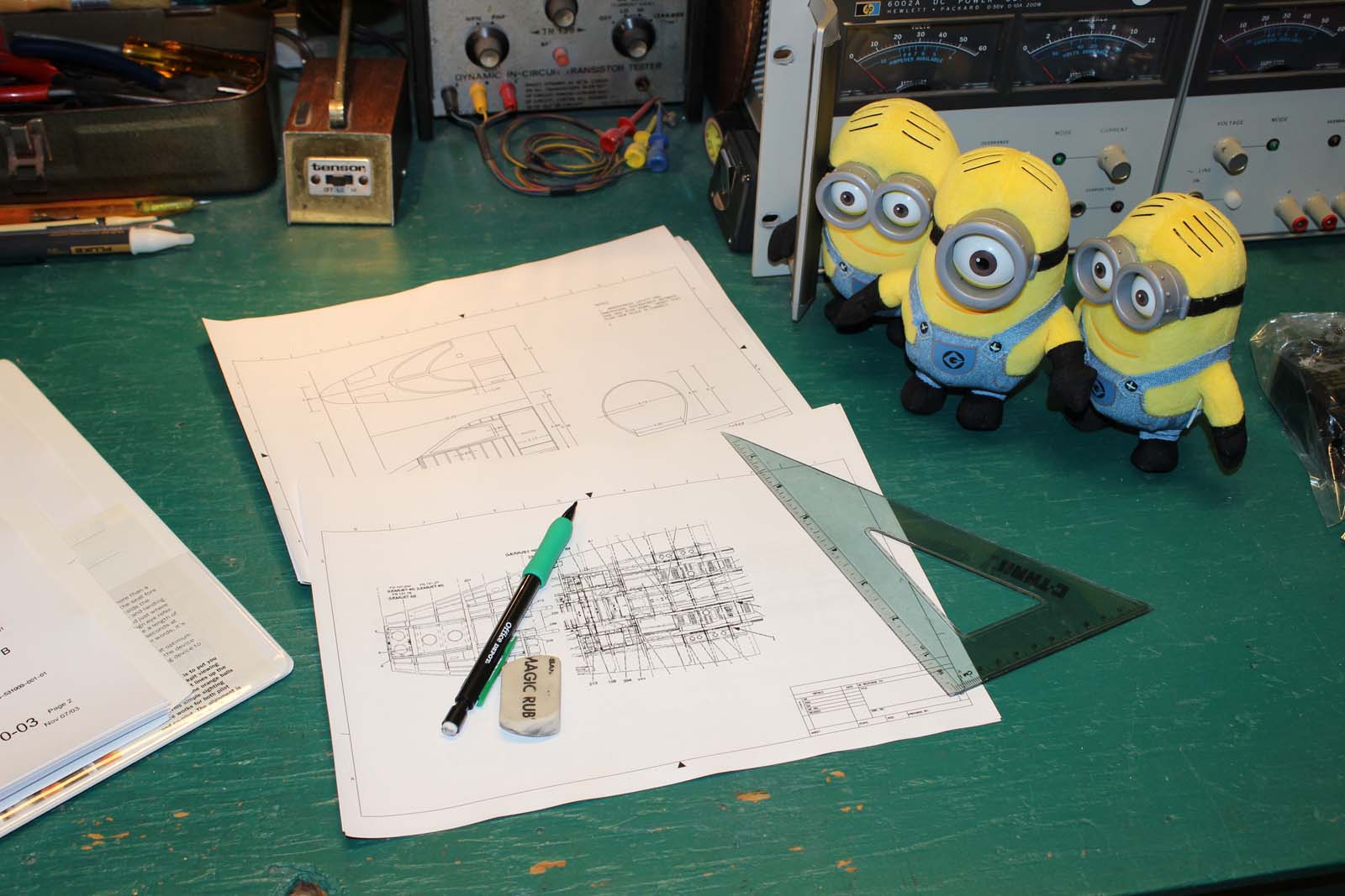
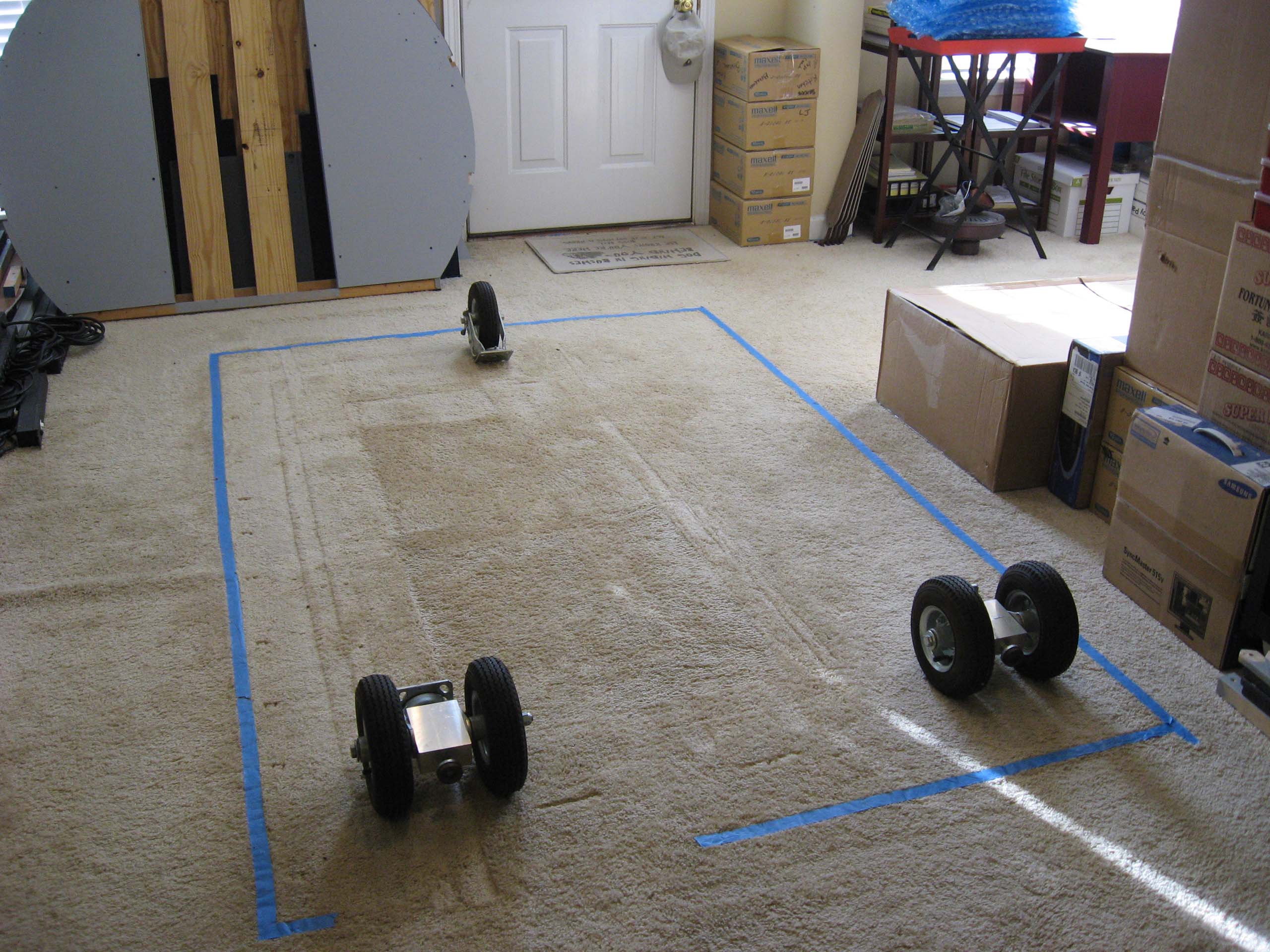
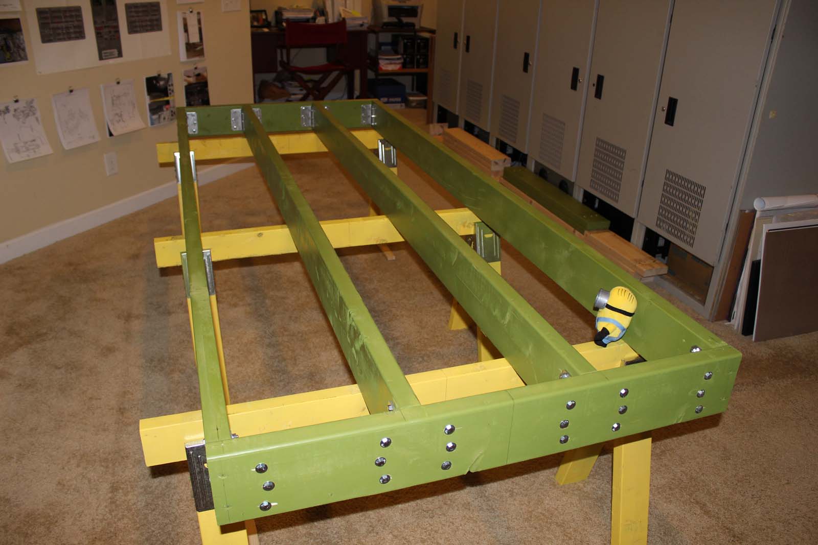
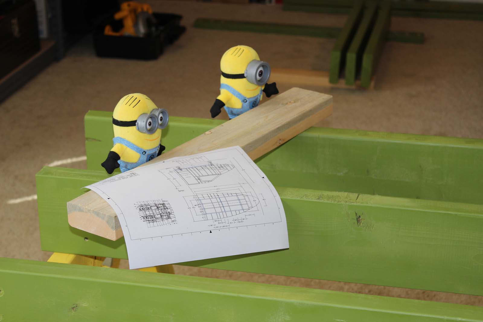
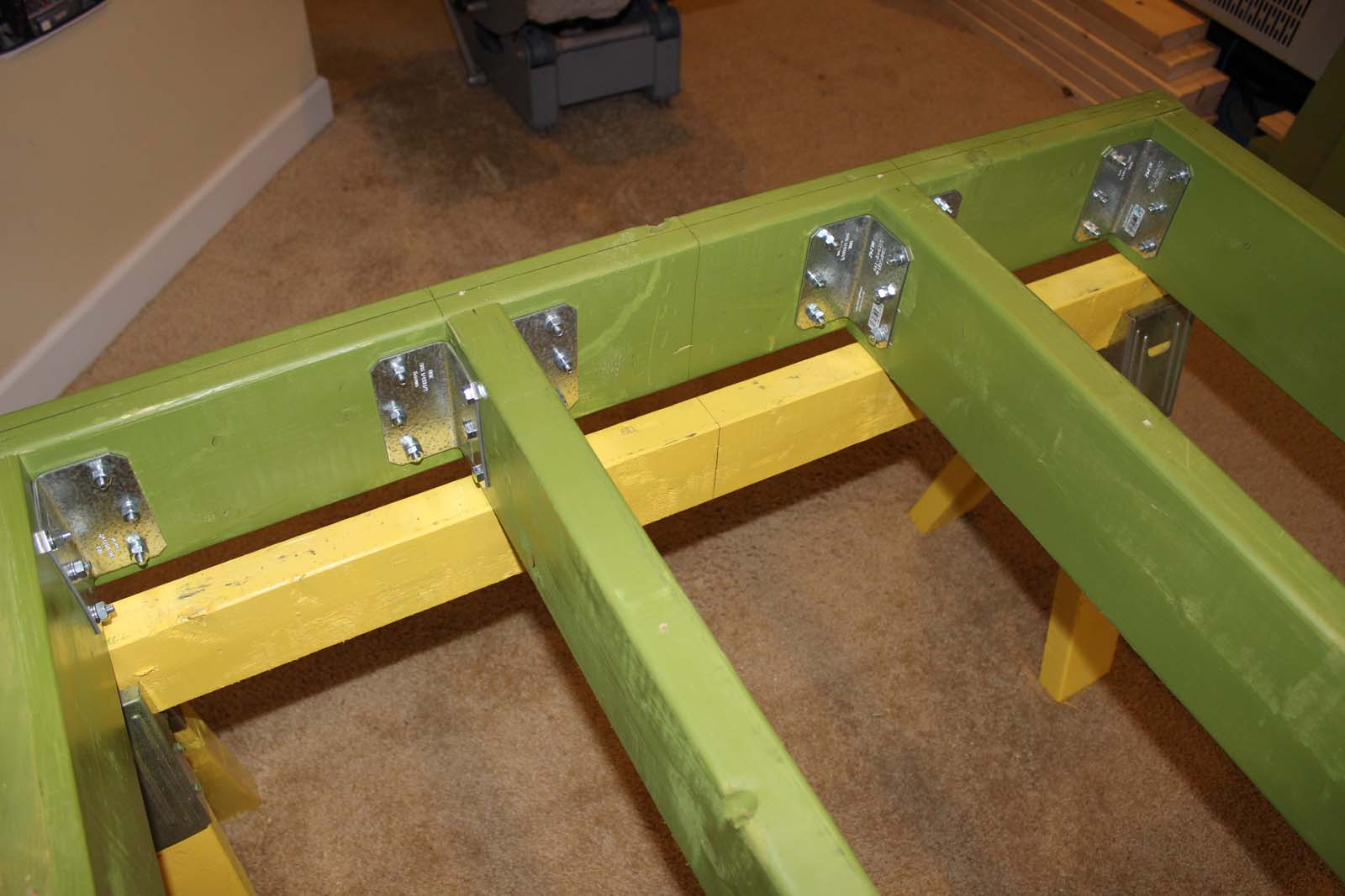
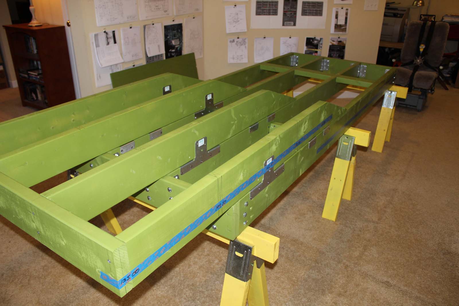
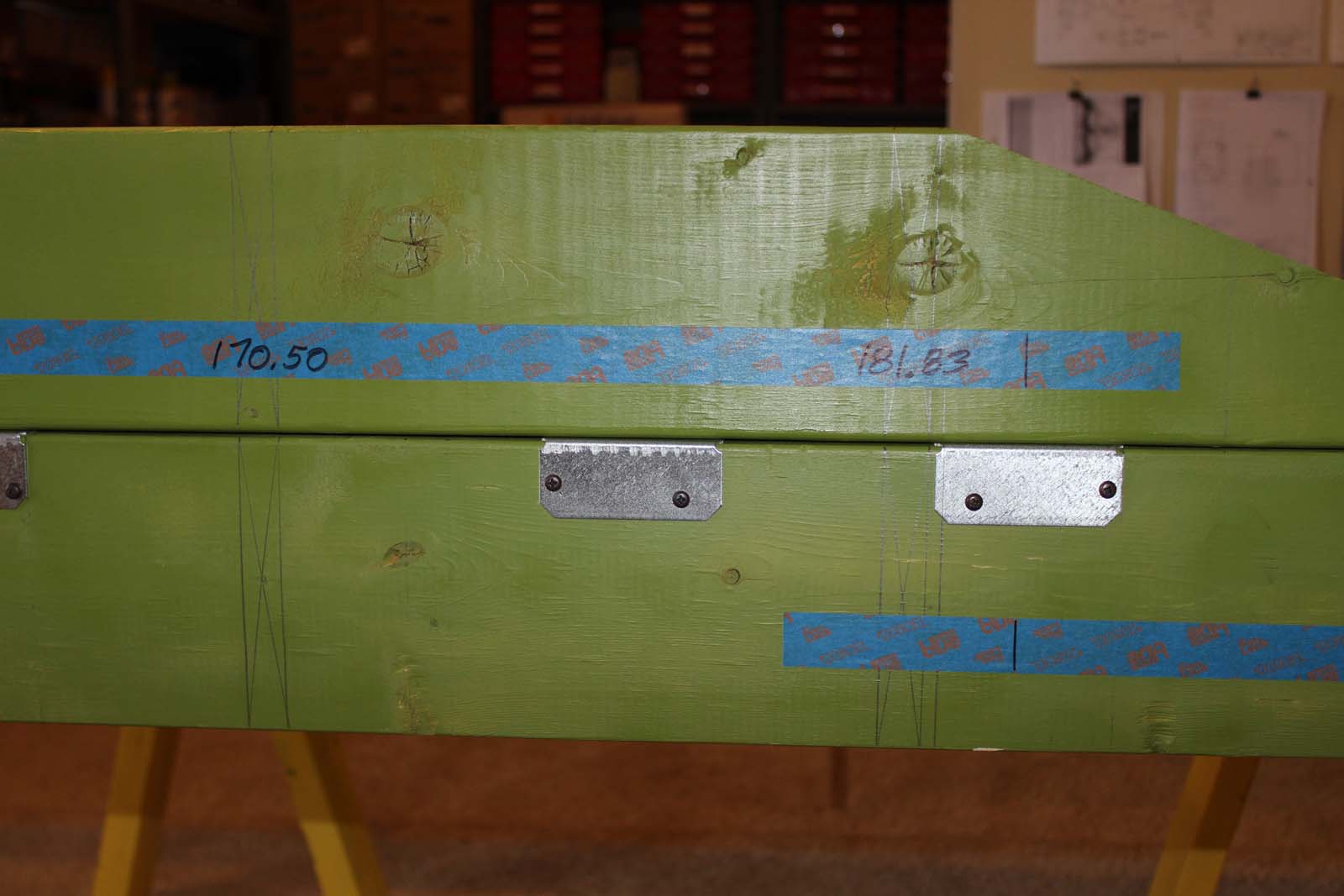
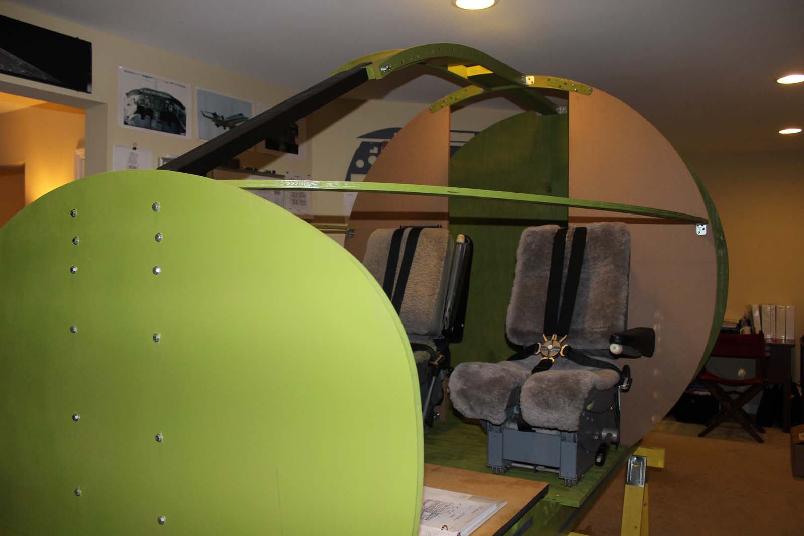
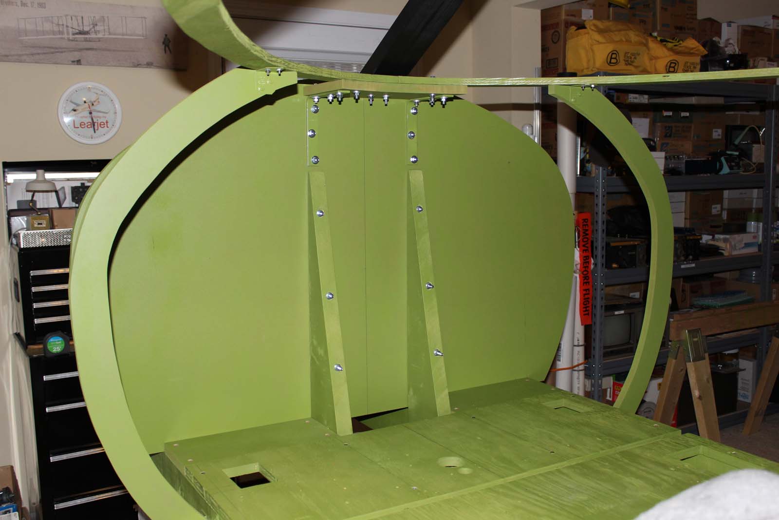
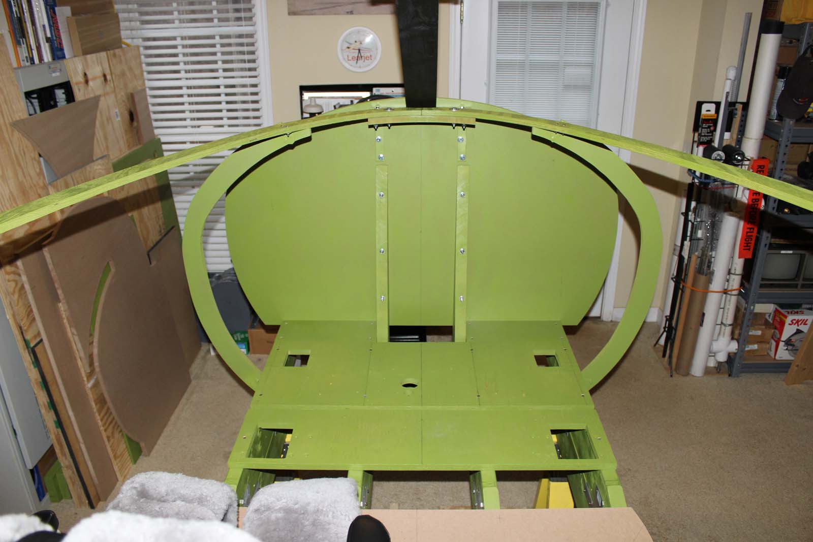
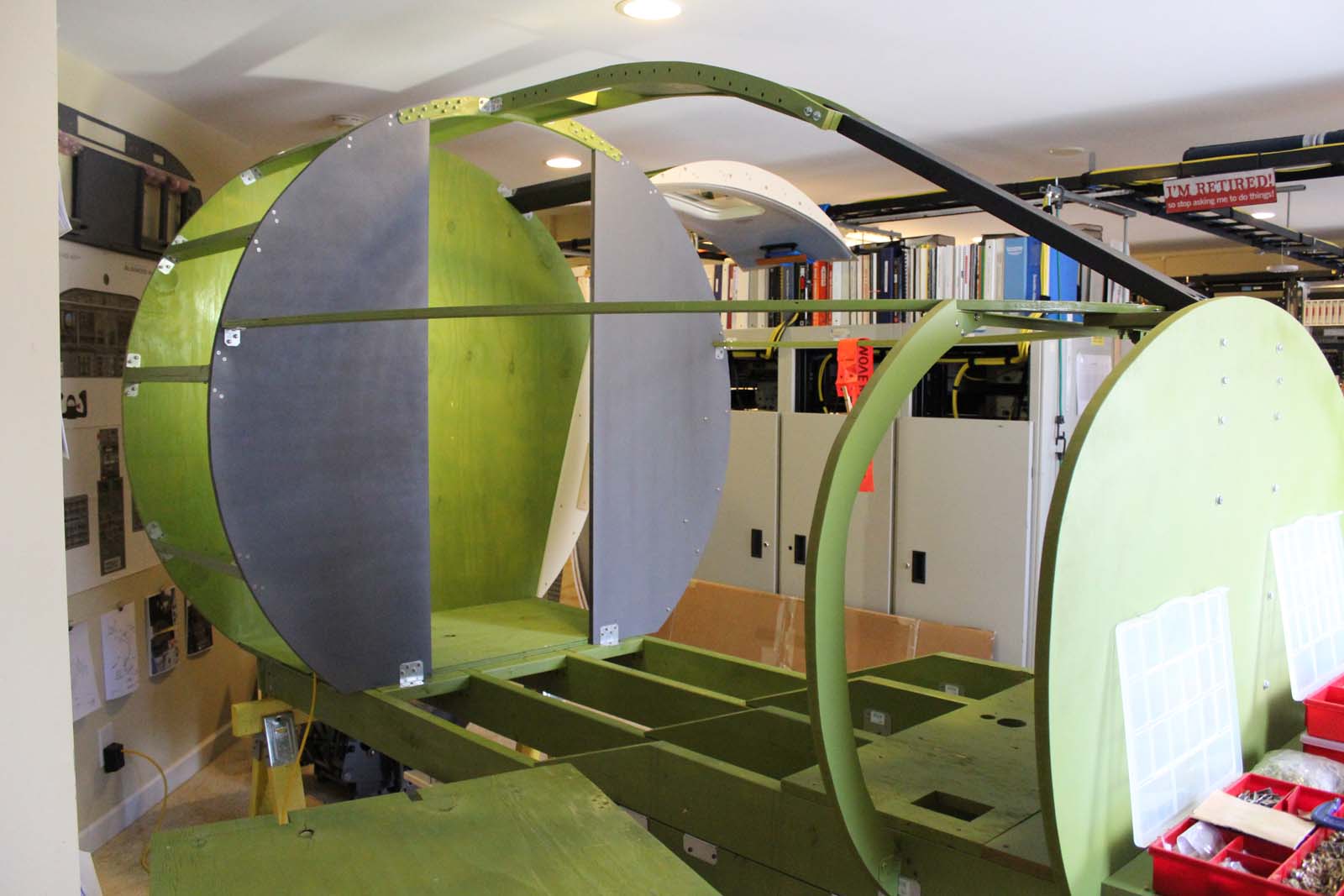
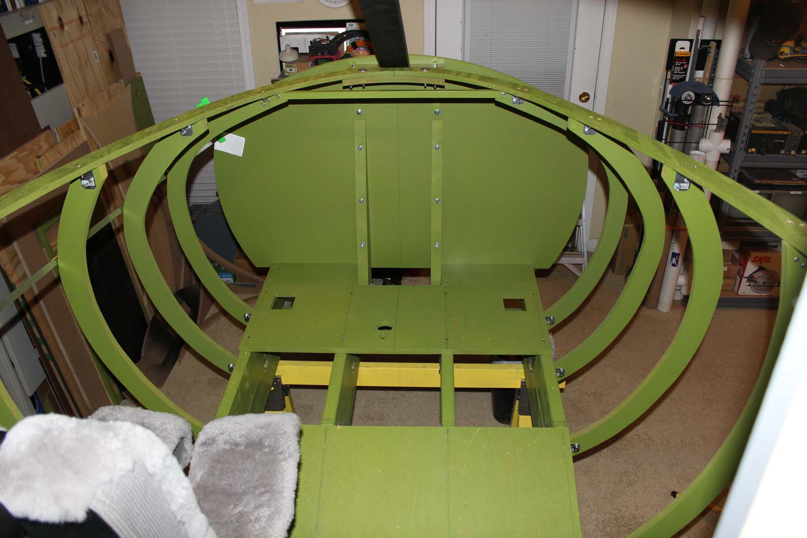
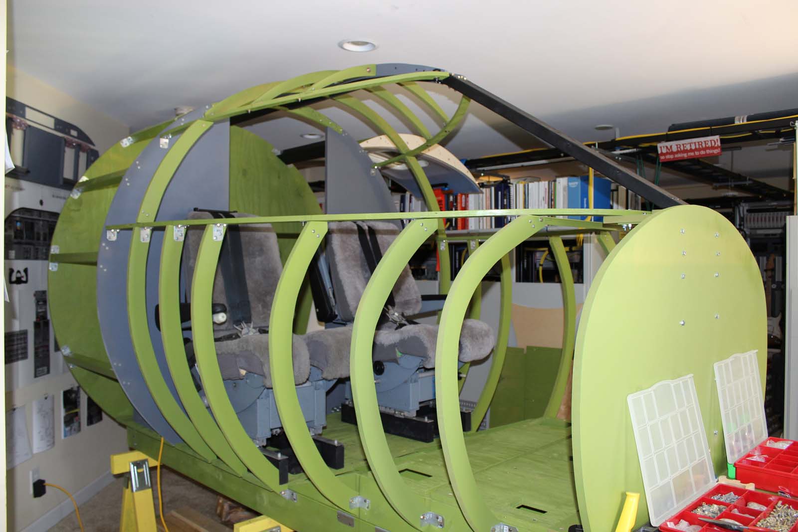
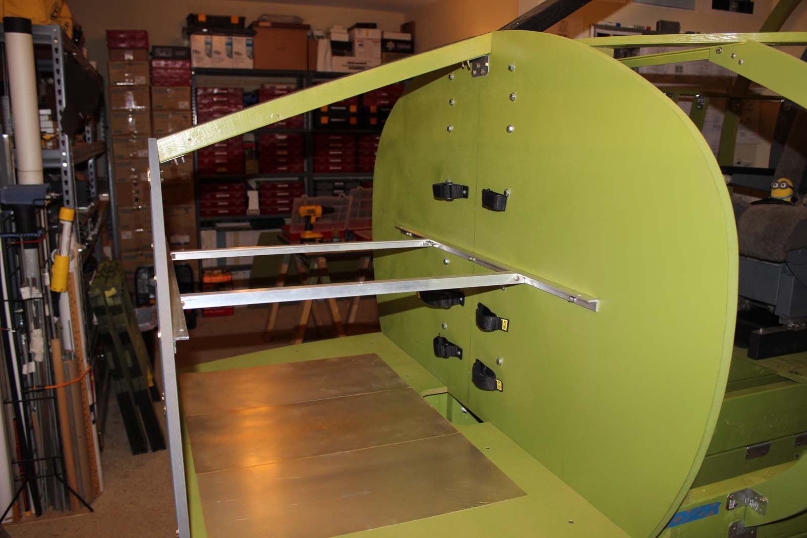
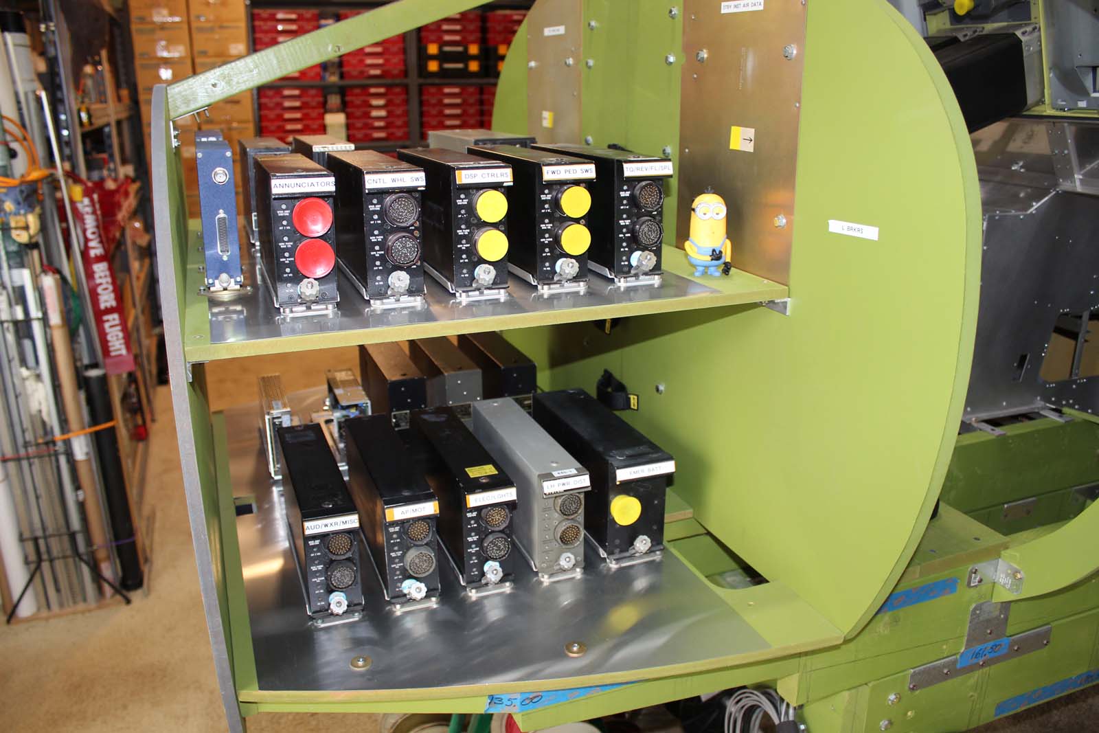
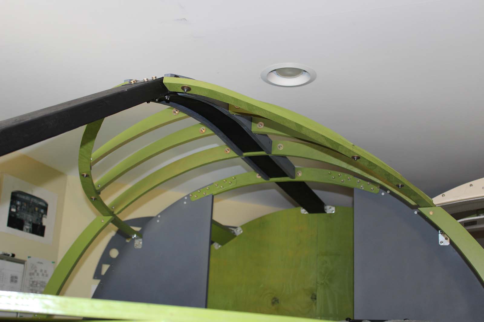
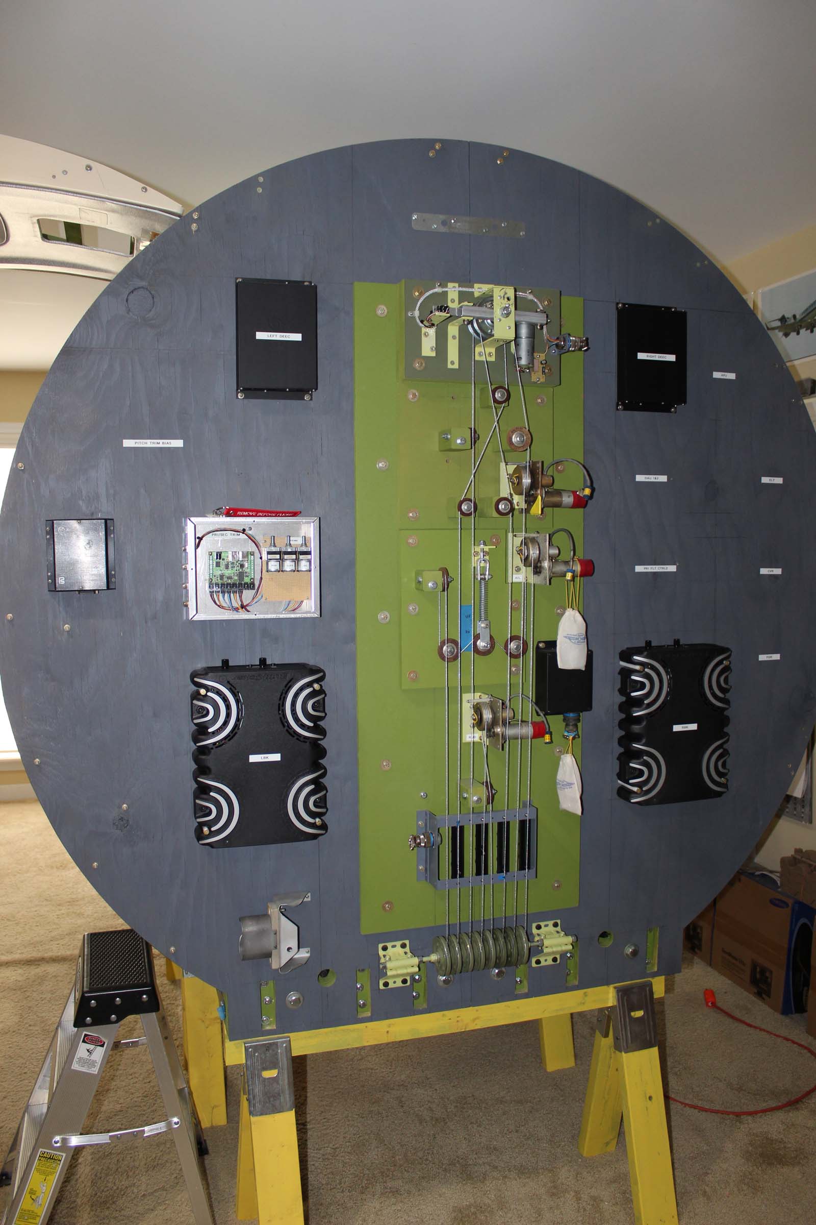
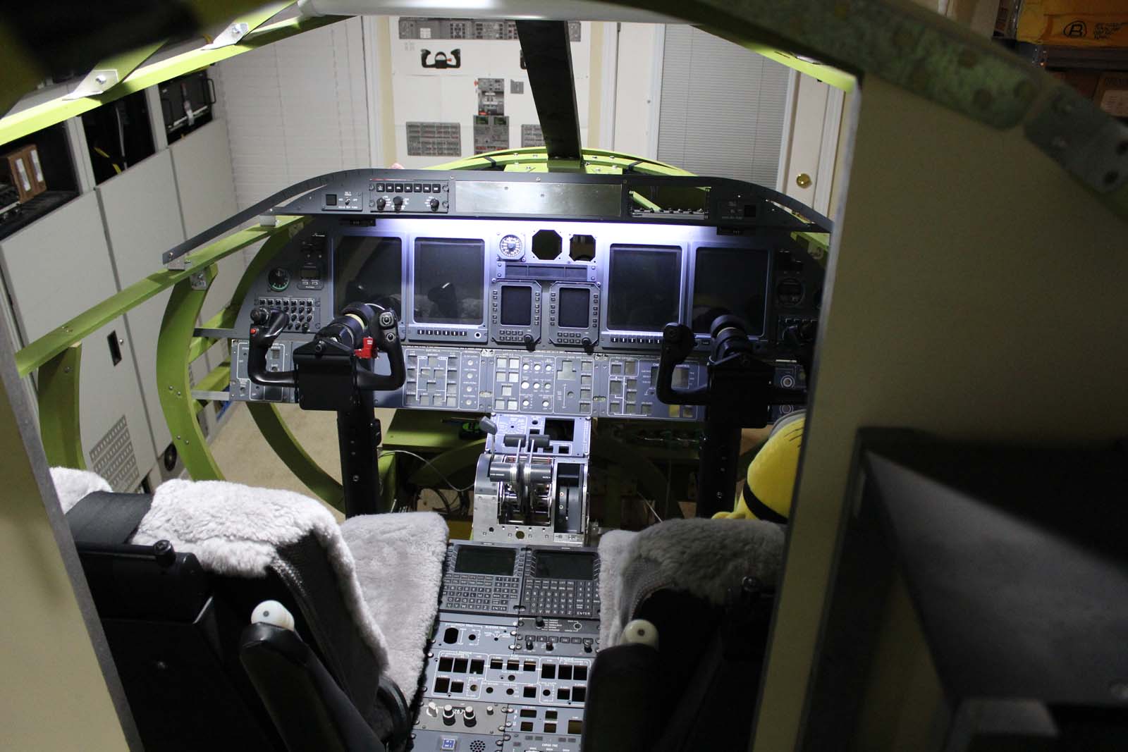
Lear 45-1001 Build History ATA Chapter 53, “Fuselage” Rev Nov 19 2018 The L45-1001 introduction contains useful background information on this build. If somehow you have arrived at this place and have not read the L45-1001 introduction you will find it HERE: The airframe for L45-1001 is constructed to full scale using a variety of materials. The primary objective was to construct an airframe that accurately replicates the dimensions of the aircraft, provides space and support for certain real avionics components, and permits ready access to parts, wiring, and components after completion. This airframe was fabricated with common tools from readily available materials. The Lear45 Structural Repair Manual contains many useful drawings of the airframe. Some of them have dimensions. The most helpful drawings show the fuselage station locations along the datum line. Using those and other known dimensions a builder can generate accurate full scale drawings from which fabrication patterns can be made. Start with good drawings and some expert help. Tip: If you import a dimensioned drawing into AutoCad and conform it to the desired scale AutoCad can pull dimensions from any desired part of the drawing. Lay out the floor space for your simulator. Make sure you have enough room before you start assembling parts that might not fit later! After I laid out the landing gear locations I realized I was gonna have to make the wings much shorter than desired. DANG! Structural members that run lengthwise with the fuselage are generally called longerons. (Shorter ones are sometimes referred to as stringers.) The Lear 45 has longerons under the floor that extend almost nose to tail. Think of these like “floor joists” in a building. This is the basic concept used in L45-1001. Aluminum longerons used in real aircraft are thinner than common wood sizes. A typical longeron is much less than 0.25” thick. When laying out the airframe for components made of wood it is necessary to compensate for the additional thickness of the wood. I placed the centerline of each wood longeron on the same centerline spacing as the real aluminum parts. My longerons are made from 2X6 lumber, but the centers of them are positioned exactly as those in the aircraft. CHECK YOUR WORK CAREFULLY before proceeding. Nearly everything else you install on the airframe will depend on the longeron centerlines being in the correct locations! If unsure about this get some expert help to check your work. Sturdy brackets and bolts hold the longerons in place. This base will eventually become the attach point for the motion system so it must be strong and rigid. Self-tapping wood screws ARE NOT ADEQUATE for this application. The aircraft fuselage tapers to a point near the nose. This presents two problems: (1) The lower plane of the L45-1001 base must remain flat to accommodate a low profile motion system. It cannot be tapered. (2) The crew compartment floor line rises just forward of the crew seats due to the taper of the fuselage. The rise in the floor line is achieved by using a second 2X6 mounted atop the base longeron. The upper longeron is attached to the lower one using metal joist brackets. These dimensions and angles can be obtained from ATA 53 drawings. Notice the blue tape along the side of the longerons. The dimensions written on that tape are the fuselage station locations pulled from ATA 53 drawings. This method provides an accurate reference by which the remainder of the fuselage components are located. I installed the major bulkheads and upper structural components prior to any of the frames. Since the locations of the bulkheads are known this was an easy method of checking my work at each step in the process. The forward pressure bulkhead and the first set of frames in place. There is no “flooring” forward of the main instrument panel, but I found it much easier to work by placing some plywood here on which to stand. The extra flooring in this photo was recovered from rig #2. It was removed during later construction. “DonnyRay, why did you paint everything green?” Aircraft aluminum parts require special primer. Zinc chromate was used for decades but it fell out of favor because it contained substances possibly harmful to human health. Zinc chromate is sort of a “dirty green” color. The modern replacement for zinc chromate is zinc phosphate primer. It’s also a dirty green color. A spray can costs about $12. My airframe is wood and does not require primer to inhibit corrosion so I use “Satin Eden” green paint from Home Depot. It costs about $3 a can and is about the same color as zinc phosphate. Non-structural metal components may also be primed with zinc phosphate in a pale yellow color. I use the zinc phosphate primers on metal parts and the Home Depot paint on wood. Notice that each frame piece is bolted to the airframe via a pair of brackets. This method provides easy access to the interior of the airframe at any stage of construction. Each frame is held in place with three bolts. Remove those three bolts and the frame can be removed thereby allowing easy access. Once the instrument panel and pedestals were installed this became a HUGE advantage during remaining construction. I intend to retain this advantage when the exterior skin is installed by using a method which preserves the ability to remove individual frames. The structural components that support the avionics bay are tapered in width to conform to the outside dimensions of the aircraft. In the real aircraft this is accomplished with bulkheads and frames that get smaller in diameter as you proceed further forward. Since it is required that the bottom surface of L45-1001 remain a flat and unobstructed plane it was impractical to use round bulkhead frames except the two seen in this photo. The avionics bay at a later stage of the build with many of the remote boxes mounted in place. A thin piece of aluminum on each shelf provides an effective single point ground for the airframe and avionics. The ceiling structural components are very similar in size and shape to those in the real aircraft. Because they are made from plywood they must be thicker than metal parts to provide the necessary strength. All of the metal brackets that fasten these were custom made from angle aluminum because they all join one another at odd angles. The upper and lower windscreen structural attach rails (called “coupe rails”) are not installed at this point in construction. The aft side of the aft bulkhead provides space for mounting the flight control system servos, flight surface sensors, DEECs, aft elevator disconnect clutch, and a variety of avionics boxes. Everything mounted here would be found somewhere aft of the cockpit in the real aircraft. Since I don’t have an “aft” in my sim, all of that stuff is mounted on this bulkhead. A recent photo illustrates how many of the pieces fit together on the airframe. HOME: This link goes to the L45-1001 build history introduction. Links to other L45-1001 posts are found at the END of the introduction. Lear 45-1001 Build History ATA Chapter 53, “Fuselage” Rev Nov 19 2018 The L45-1001 introduction contains useful background information on this build. If somehow you have arrived at this place and have not read the L45-1001 introduction you will find it HERE: The airframe for L45-1001 is constructed to full scale using a variety of materials. The primary objective was to construct an airframe that accurately replicates the dimensions of the aircraft, provides space and support for certain real avionics components, and permits ready access to parts, wiring, and components after completion. This airframe was fabricated with common tools from readily available materials. The Lear45 Structural Repair Manual contains many useful drawings of the airframe. Some of them have dimensions. The most helpful drawings show the fuselage station locations along the datum line. Using those and other known dimensions a builder can generate accurate full scale drawings from which fabrication patterns can be made. Start with good drawings and some expert help. Tip: If you import a dimensioned drawing into AutoCad and conform it to the desired scale AutoCad can pull dimensions from any desired part of the drawing. Lay out the floor space for your simulator. Make sure you have enough room before you start assembling parts that might not fit later! After I laid out the landing gear locations I realized I was gonna have to make the wings much shorter than desired. DANG! Structural members that run lengthwise with the fuselage are generally called longerons. (Shorter ones are sometimes referred to as stringers.) The Lear 45 has longerons under the floor that extend almost nose to tail. Think of these like “floor joists” in a building. This is the basic concept used in L45-1001. Aluminum longerons used in real aircraft are thinner than common wood sizes. A typical longeron is much less than 0.25” thick. When laying out the airframe for components made of wood it is necessary to compensate for the additional thickness of the wood. I placed the centerline of each wood longeron on the same centerline spacing as the real aluminum parts. My longerons are made from 2X6 lumber, but the centers of them are positioned exactly as those in the aircraft. CHECK YOUR WORK CAREFULLY before proceeding. Nearly everything else you install on the airframe will depend on the longeron centerlines being in the correct locations! If unsure about this get some expert help to check your work. Sturdy brackets and bolts hold the longerons in place. This base will eventually become the attach point for the motion system so it must be strong and rigid. Self-tapping wood screws ARE NOT ADEQUATE for this application. The aircraft fuselage tapers to a point near the nose. This presents two problems: (1) The lower plane of the L45-1001 base must remain flat to accommodate a low profile motion system. It cannot be tapered. (2) The crew compartment floor line rises just forward of the crew seats due to the taper of the fuselage. The rise in the floor line is achieved by using a second 2X6 mounted atop the base longeron. The upper longeron is attached to the lower one using metal joist brackets. These dimensions and angles can be obtained from ATA 53 drawings. Notice the blue tape along the side of the longerons. The dimensions written on that tape are the fuselage station locations pulled from ATA 53 drawings. This method provides an accurate reference by which the remainder of the fuselage components are located. I installed the major bulkheads and upper structural components prior to any of the frames. Since the locations of the bulkheads are known this was an easy method of checking my work at each step in the process. The forward pressure bulkhead and the first set of frames in place. There is no “flooring” forward of the main instrument panel, but I found it much easier to work by placing some plywood here on which to stand. The extra flooring in this photo was recovered from rig #2. It was removed during later construction. “DonnyRay, why did you paint everything green?” Aircraft aluminum parts require special primer. Zinc chromate was used for decades but it fell out of favor because it contained substances possibly harmful to human health. Zinc chromate is sort of a “dirty green” color. The modern replacement for zinc chromate is zinc phosphate primer. It’s also a dirty green color. A spray can costs about $12. My airframe is wood and does not require primer to inhibit corrosion so I use “Satin Eden” green paint from Home Depot. It costs about $3 a can and is about the same color as zinc phosphate. Non-structural metal components may also be primed with zinc phosphate in a pale yellow color. I use the zinc phosphate primers on metal parts and the Home Depot paint on wood. Notice that each frame piece is bolted to the airframe via a pair of brackets. This method provides easy access to the interior of the airframe at any stage of construction. Each frame is held in place with three bolts. Remove those three bolts and the frame can be removed thereby allowing easy access. Once the instrument panel and pedestals were installed this became a HUGE advantage during remaining construction. I intend to retain this advantage when the exterior skin is installed by using a method which preserves the ability to remove individual frames. The structural components that support the avionics bay are tapered in width to conform to the outside dimensions of the aircraft. In the real aircraft this is accomplished with bulkheads and frames that get smaller in diameter as you proceed further forward. Since it is required that the bottom surface of L45-1001 remain a flat and unobstructed plane it was impractical to use round bulkhead frames except the two seen in this photo. The avionics bay at a later stage of the build with many of the remote boxes mounted in place. A thin piece of aluminum on each shelf provides an effective single point ground for the airframe and avionics. The ceiling structural components are very similar in size and shape to those in the real aircraft. Because they are made from plywood they must be thicker than metal parts to provide the necessary strength. All of the metal brackets that fasten these were custom made from angle aluminum because they all join one another at odd angles. The upper and lower windscreen structural attach rails (called “coupe rails”) are not installed at this point in construction. The aft side of the aft bulkhead provides space for mounting the flight control system servos, flight surface sensors, DEECs, aft elevator disconnect clutch, and a variety of avionics boxes. Everything mounted here would be found somewhere aft of the cockpit in the real aircraft. Since I don’t have an “aft” in my sim, all of that stuff is mounted on this bulkhead. A recent photo illustrates how many of the pieces fit together on the airframe. HOME: This link goes to the L45-1001 build history introduction. Links to other L45-1001 posts are found at the END of the introduction. Great work DonnyRay! I have seen L45-1001 in person two times now and it is beyond impressive! I am taking a lot of notes on this build to implement into my own sim and possibly a second sim down the road! Looking forward to seeing your next chapters posted up. Again, Outstanding work! Great work DonnyRay! I have seen L45-1001 in person two times now and it is beyond impressive! I am taking a lot of notes on this build to implement into my own sim and possibly a second sim down the road! Looking forward to seeing your next chapters posted up. Again, Outstanding work! Post I have been waiting to see since forever! Thank you DonnyRay! Very Impressive! Post I have been waiting to see since forever! Thank you DonnyRay! Very Impressive!L45-1001 ATA-53, Fuselage
![]()
![]()
![]()
2017-10-10