


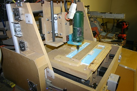
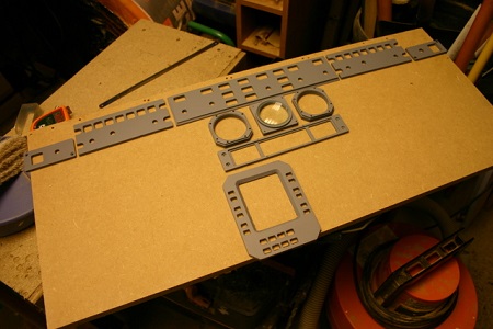
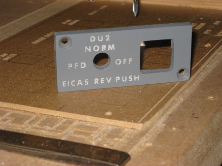
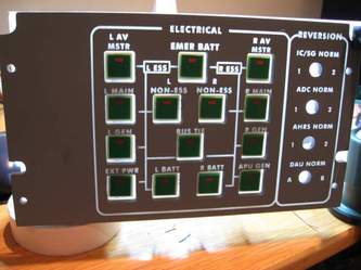
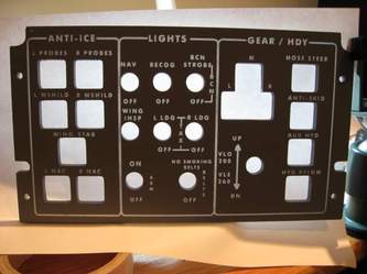
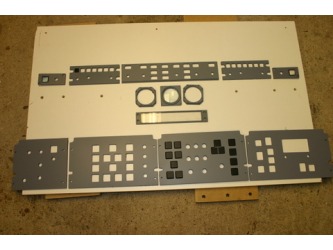
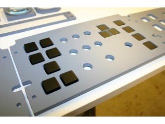
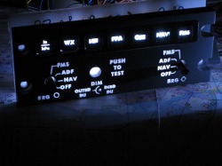
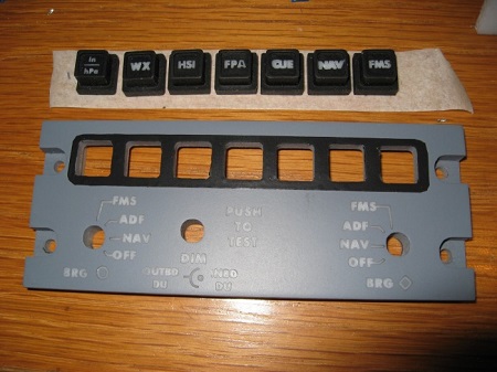
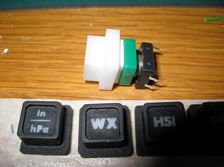
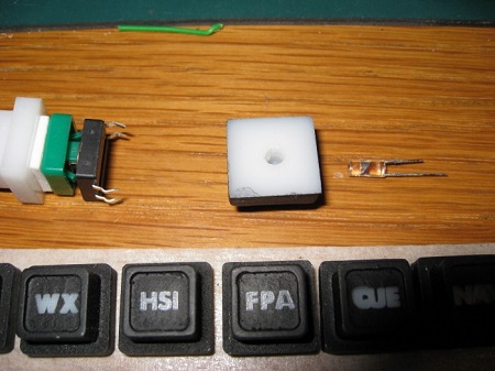
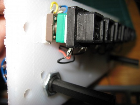
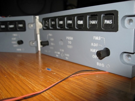
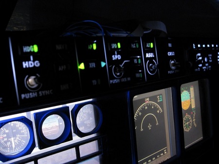
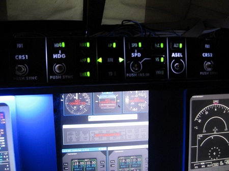
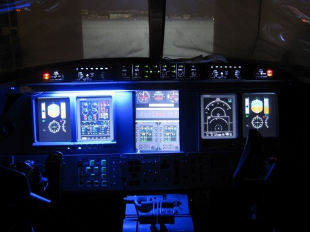
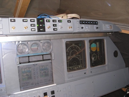
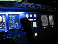
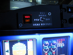
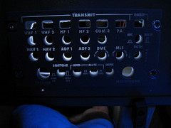
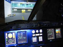
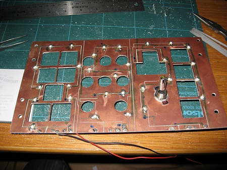
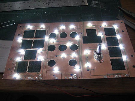
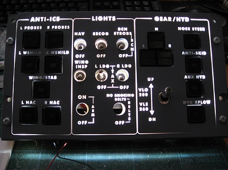
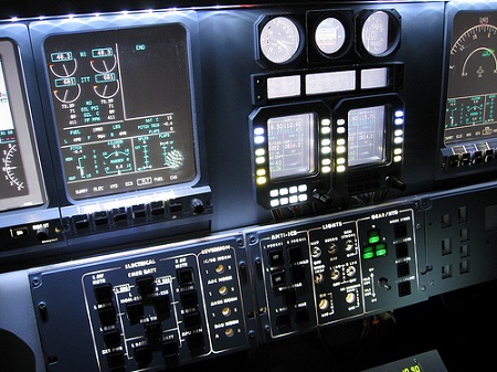
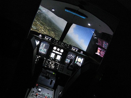
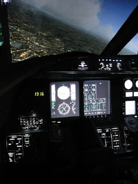
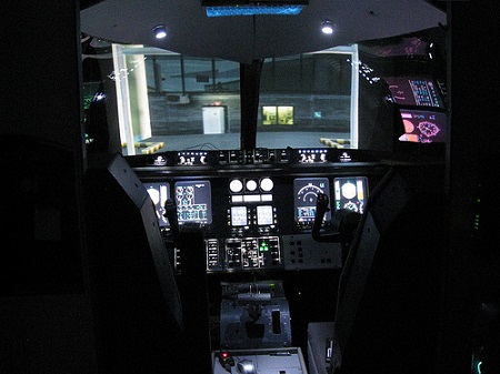
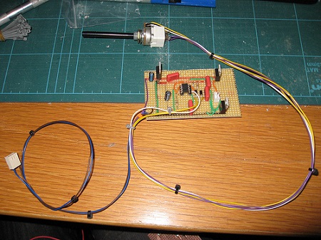
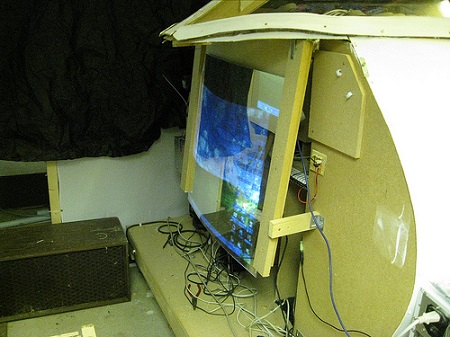
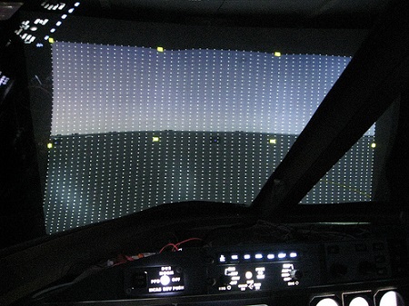
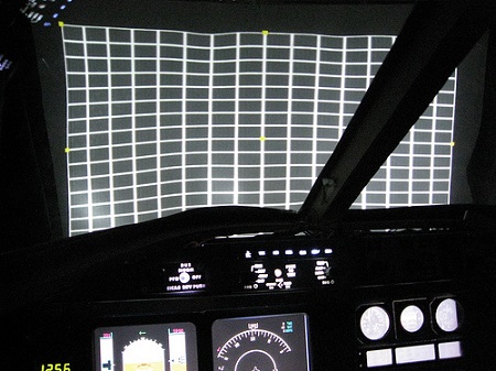
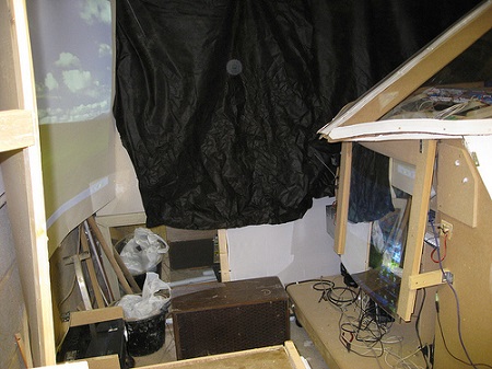
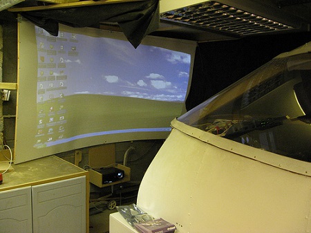
(Original thread started on 08-29-09 by Douglas Dick) I have been working on building a CNC for some time and have now got to working. Its not very pretty but it works and cost less than £200 to build: I have cut my first test panels but have yet to have a go at engraving. Again many thanks to Vince for the excellent tutorials on how to do this: Yes I know I am slow at posting on the site ( but I read plenty about the fantastic work that is going on) but I thought it was time to give an up date on where I am. I am learning (mostly the hard way) that CNC engraving is not easy. However it is good to see things getting better even when you see the panel that has taken an hour or more to machine and day to paint and dry get messed up in the engraving ( who said that it would be easy ): I have had an attempt at engraving the electrical panel, lights/gear/hyd panel and the FGC They look okay but each has some minor flaw to be fixed but it is good to know that I can make them even if I need to re do them to correct the errors: The plastic that I was using for the panels unfortunately looks a bit grey rather than white in daylight but it looks okay when back lit, which it will be most of the time after the effort in making it possible. After trying all over eBay and failing to find some, I have final found a supplier for 10mm translucent cast acrylic, what's even better is that it is a small fabrication shop only 10 miles from me so no postage or credit card involved. The guy that owns it sold me a large sheet of 6 mm Lexan for £10 and gave me a length of 10mm white for free, good deal to me. I have also got a box of 50 push switches for only £22 on eBay They are similar to AMLs but I think slightly smaller (17mm cut out). They are momentary but have a good click when you push them. I have come up with a way to fit a front on them that looks more Learjet: To put the slight frustration of engraving to the side for a while I have built a second PC for the sim, 'yes I have joined the network'. Maplin electronics was selling a AMD3200 and motherboard for £45, so along with an old PC and some parts including a new power supply that I had it was a cheap build. I have down loaded Dave's gauges and wideFS and have to say that it was very easy to get it all working. Dave's software is amazing, I just installed it and it just works!!! ( Mr Gates could learn a thing or two from that) The motherboard has built in graphics but also has a PCI-e slot so when funds allow I can install a graphics card and drive at least one other monitors from there. (Posted by Vince on 08-29-09) I can really appreciate your efforts in making the panels and I think you had a good start that just needs to be improved a bit. What I would suggest is to use the right fonts and size for the characters. That will make a huge difference in the overall look of them. The right font for the lower MIP panels is the FuturaBT Medium or Futura Md BT (those are the same). The right font for the buttons hasn't ever been digitized so you can go for the nearest substitute that is the EuroTechnic condensed font. About plastics I think that the problem is that most polycarbonates (like lexan is) only come in an opal color that looks a bit grey/green after painted and engraved making it hardly readable with daylight. The right choice should be getting some cast acrylic in a full milk white color. Anyway I understand that that might be expensive and you want to follow a cheaper way. Keep up with the great work and progress! (Posted by Douglas Dick on 08-30-09) Thanks for the support! The type of plastic does make a big difference to how things work out. The 10mm block of cast acrylic that I got from the local workshop machines very different and much better to the 5mm sheets that I have used for the main panels. I will need to pay another visit and see what I can get. I have used the correct font so it must be the spacing and size that is not so good. I tried a test using the RMU file from Vince, that proved to me that my home made CNC can do the job as it engraves the word TUNE very well. I have replicated as many settings from that file as I can see although the cutter is a 30 degree rather than 45. I noticed that the letters on that file highlight individually rather than in a block like mine, is there a reason for that? I have set the font and size then typed the text in Artcam then positioned it on the panel. Do you place each letter on its own? Also how do you engrave the lines. I have worked out that I can draw a rounded rectangle in Artcam and cut the vector ( to leave a space where a word like ELECTRICAL should be) to make the lines that go around the sections of the panel, but how should I machine them. I have used 'machine along the vector' but is there a better way? Had a good weekend with the CNC running most of it. I got most of the lower panels cut and started making switch fronts and the gear indicators. This CNC thing is so cool, when you draw a part and the machine makes it for you. Even making parts like the gear indicator the cut parts fit into the cut holes first time I have ordered the engraving cutters and cant wait to see a panel engraved: Okay you sometimes just reach that moment when you want to share some success, but the wife and family just don`t understand. EFIS with Christmas back lighting! As my hangar is under snow at the moment I thought I would post some pictures of how I made the my EFIS panels. With much thanks to Vince for the direction on the CNC I have been able to machine and engrave a pair of EFIS panels to a reasonable standard: I have made the switch cap as a single part from the same 10mm cast acrylic as the panel. I drilled a 3mm hole in the back and fitted my 3mm flat top LEDs from the Christmas lights: The legs are then bent over and a square of extra strong foam mounting tape is attached to the back. This holds the LED and fixes the cap to the switch cap. I am using 12mm square Omron tactile switches: I don`t have the skills to make a PCB backer so I have used a plastic panel to hold the switches in place. The hard plastic backing panel has a number of holes drill in it that I can push other LEDs through to light the rest of the panel: (Original thread started on 08-29-09 by Douglas Dick) I have been working on building a CNC for some time and have now got to working. Its not very pretty but it works and cost less than £200 to build: I have cut my first test panels but have yet to have a go at engraving. Again many thanks to Vince for the excellent tutorials on how to do this: Yes I know I am slow at posting on the site ( but I read plenty about the fantastic work that is going on) but I thought it was time to give an up date on where I am. I am learning (mostly the hard way) that CNC engraving is not easy. However it is good to see things getting better even when you see the panel that has taken an hour or more to machine and day to paint and dry get messed up in the engraving ( who said that it would be easy ): I have had an attempt at engraving the electrical panel, lights/gear/hyd panel and the FGC They look okay but each has some minor flaw to be fixed but it is good to know that I can make them even if I need to re do them to correct the errors: The plastic that I was using for the panels unfortunately looks a bit grey rather than white in daylight but it looks okay when back lit, which it will be most of the time after the effort in making it possible. After trying all over eBay and failing to find some, I have final found a supplier for 10mm translucent cast acrylic, what's even better is that it is a small fabrication shop only 10 miles from me so no postage or credit card involved. The guy that owns it sold me a large sheet of 6 mm Lexan for £10 and gave me a length of 10mm white for free, good deal to me. I have also got a box of 50 push switches for only £22 on eBay They are similar to AMLs but I think slightly smaller (17mm cut out). They are momentary but have a good click when you push them. I have come up with a way to fit a front on them that looks more Learjet: To put the slight frustration of engraving to the side for a while I have built a second PC for the sim, 'yes I have joined the network'. Maplin electronics was selling a AMD3200 and motherboard for £45, so along with an old PC and some parts including a new power supply that I had it was a cheap build. I have down loaded Dave's gauges and wideFS and have to say that it was very easy to get it all working. Dave's software is amazing, I just installed it and it just works!!! ( Mr Gates could learn a thing or two from that) The motherboard has built in graphics but also has a PCI-e slot so when funds allow I can install a graphics card and drive at least one other monitors from there. (Posted by Vince on 08-29-09) I can really appreciate your efforts in making the panels and I think you had a good start that just needs to be improved a bit. What I would suggest is to use the right fonts and size for the characters. That will make a huge difference in the overall look of them. The right font for the lower MIP panels is the FuturaBT Medium or Futura Md BT (those are the same). The right font for the buttons hasn't ever been digitized so you can go for the nearest substitute that is the EuroTechnic condensed font. About plastics I think that the problem is that most polycarbonates (like lexan is) only come in an opal color that looks a bit grey/green after painted and engraved making it hardly readable with daylight. The right choice should be getting some cast acrylic in a full milk white color. Anyway I understand that that might be expensive and you want to follow a cheaper way. Keep up with the great work and progress! (Posted by Douglas Dick on 08-30-09) Thanks for the support! The type of plastic does make a big difference to how things work out. The 10mm block of cast acrylic that I got from the local workshop machines very different and much better to the 5mm sheets that I have used for the main panels. I will need to pay another visit and see what I can get. I have used the correct font so it must be the spacing and size that is not so good. I tried a test using the RMU file from Vince, that proved to me that my home made CNC can do the job as it engraves the word TUNE very well. I have replicated as many settings from that file as I can see although the cutter is a 30 degree rather than 45. I noticed that the letters on that file highlight individually rather than in a block like mine, is there a reason for that? I have set the font and size then typed the text in Artcam then positioned it on the panel. Do you place each letter on its own? Also how do you engrave the lines. I have worked out that I can draw a rounded rectangle in Artcam and cut the vector ( to leave a space where a word like ELECTRICAL should be) to make the lines that go around the sections of the panel, but how should I machine them. I have used 'machine along the vector' but is there a better way? Had a good weekend with the CNC running most of it. I got most of the lower panels cut and started making switch fronts and the gear indicators. This CNC thing is so cool, when you draw a part and the machine makes it for you. Even making parts like the gear indicator the cut parts fit into the cut holes first time I have ordered the engraving cutters and cant wait to see a panel engraved: Okay you sometimes just reach that moment when you want to share some success, but the wife and family just don`t understand. EFIS with Christmas back lighting! As my hangar is under snow at the moment I thought I would post some pictures of how I made the my EFIS panels. With much thanks to Vince for the direction on the CNC I have been able to machine and engrave a pair of EFIS panels to a reasonable standard: I have made the switch cap as a single part from the same 10mm cast acrylic as the panel. I drilled a 3mm hole in the back and fitted my 3mm flat top LEDs from the Christmas lights: The legs are then bent over and a square of extra strong foam mounting tape is attached to the back. This holds the LED and fixes the cap to the switch cap. I am using 12mm square Omron tactile switches: I don`t have the skills to make a PCB backer so I have used a plastic panel to hold the switches in place. The hard plastic backing panel has a number of holes drill in it that I can push other LEDs through to light the rest of the panel: Thought it was time for a bit of an update and a cockpit video. It was a bit harder to do than I expected getting a video camera into the sim and having enough space to get everything in the shot but here is my effort from the weekend: https://youtu.be/XnbNun85grM There is much work to be done as I have re made all the lower panels out of 10mm white/translucent acrylic, they are painted but not engraved yet. The RMU buttons also need a paint and engraving but my key task is to get as much working as possibly then work on the fine detail. All the new panels are connected with multi plugs so each can be easily removed for further work. Check out my website for additional details and photos! (Posted by Douglas Dick on 02-13-10) Its been a while from my last post but don`t worry I have been working hard on the sim. I have updated to FSX and the required FSUIPC and I have completed the two EFIS panels. The FGC almost ready: I have pulled together the open cockpits cards and connected them to the EFIS and the FGC. I have taken on board the advice about cabling and removed the boards from the old PC case and fitted them behind the MIP. This will keep the ribbon cable as short as possible. I have used up almost all the inputs on the master card so I have ordered an other one. I am just using the IOcards software at the moment, SIOC can wait until I have more time. Just a lesson I learned the hard way if you use OCcard don`t add any blank lines to the page in config as i did then spent two days trying to work out why it would not run. I have most of the basic functions of the FGC setup but I need to re read Eric`s post on how the V-speed should work.( I think it may stay the simple way unless there is new FGC software) I got the Jet45 XFR function to work and the LEDs to change from left to Right I still need to find or make a switch for the master/caution panel but I have tested the DU2 DU3 swap by setting it up on the WX button on the EFIS. It`s good to finally get some parts together and working, It seems like I have been making parts for months that don't do any thing but it is worth it now. I have even managed to have a go at a bit of flying (not done much of that during the build) Its not until you try flying the sim that you find that some offset is wrong and something does not work, you also find that you wish you had another switch set up ( I cant wait to get RMUs up and working) I have seen bits of jet45 that I did not know existed and realized how much I don’t understand about flying the Learjet. I am looking forward to being able to learn by flying the sim. With all the good work going on and everyone at the hangar working together we should have many sims working over the coming year. (Posted by Eric Tomlin on 02-18-10) That's a nice surprise, but a surprise none the less. I discovered the same thing as we started building the details into JET45. Many little things that I think lots of customers still haven't seen or noticed yet. It's easy to see that there's no CDU as of today, but what about all the cool features that really make this a detailed package that makes it like flying a Learjet and not just a generic jet? If you ever have a flying question, please don't hesitate to ask or email me as we are here to share the info. (Posted by Douglas Dick on 03-31-10) I thought I would post some pictures of where I am with my sim: I recently bought a set of Ron's switch cover: The audio panels along with the RMUs are cut and I have one of the RMU circuit boards made up and working I just need to make the buttons and put them together. They are not as refined as the work Vince produces, but I am pleased that I have been able to make my own: The problem now is that I am now having so much fun flying, I am finding it hard to go back to building! Time for an up date. I have been working on back lighting using surface mount LEDs. I know others have used them but for any one who hasn't here are some pictures: This is the gear PCB. I have not made any complex PCBs just used the CNC to cut the holes in the copper board and cut it to size. I then engraved a track to allow me to position the surface mount LEDs across the engraved line. I am sure that there is a better way to do this but that's another learning curve: http://www.flickr.com/photos/48890681@N04/4917586246/ The board made up and tested: The front panel with Ron's switch caps. I am not using real AML switched I have just made covers to fit the caps: http://www.flickr.com/photos/48890681@N04/4917593250/ I have just seen the update to jet45 I will install this and let you know how it works out in the next few days. Thought it was time for a bit of an update and a cockpit video. It was a bit harder to do than I expected getting a video camera into the sim and having enough space to get everything in the shot but here is my effort from the weekend: There is much work to be done as I have re made all the lower panels out of 10mm white/translucent acrylic, they are painted but not engraved yet. The RMU buttons also need a paint and engraving but my key task is to get as much working as possibly then work on the fine detail. All the new panels are connected with multi plugs so each can be easily removed for further work. Check out my website for additional details and photos! (Posted by Douglas Dick on 02-13-10) Its been a while from my last post but don`t worry I have been working hard on the sim. I have updated to FSX and the required FSUIPC and I have completed the two EFIS panels. The FGC almost ready: I have pulled together the open cockpits cards and connected them to the EFIS and the FGC. I have taken on board the advice about cabling and removed the boards from the old PC case and fitted them behind the MIP. This will keep the ribbon cable as short as possible. I have used up almost all the inputs on the master card so I have ordered an other one. I am just using the IOcards software at the moment, SIOC can wait until I have more time. Just a lesson I learned the hard way if you use OCcard don`t add any blank lines to the page in config as i did then spent two days trying to work out why it would not run. I have most of the basic functions of the FGC setup but I need to re read Eric`s post on how the V-speed should work.( I think it may stay the simple way unless there is new FGC software) I got the Jet45 XFR function to work and the LEDs to change from left to Right I still need to find or make a switch for the master/caution panel but I have tested the DU2 DU3 swap by setting it up on the WX button on the EFIS. It`s good to finally get some parts together and working, It seems like I have been making parts for months that don't do any thing but it is worth it now. I have even managed to have a go at a bit of flying (not done much of that during the build) Its not until you try flying the sim that you find that some offset is wrong and something does not work, you also find that you wish you had another switch set up ( I cant wait to get RMUs up and working) I have seen bits of jet45 that I did not know existed and realized how much I don’t understand about flying the Learjet. I am looking forward to being able to learn by flying the sim. With all the good work going on and everyone at the hangar working together we should have many sims working over the coming year. (Posted by Eric Tomlin on 02-18-10) That's a nice surprise, but a surprise none the less. I discovered the same thing as we started building the details into JET45. Many little things that I think lots of customers still haven't seen or noticed yet. It's easy to see that there's no CDU as of today, but what about all the cool features that really make this a detailed package that makes it like flying a Learjet and not just a generic jet? If you ever have a flying question, please don't hesitate to ask or email me as we are here to share the info. (Posted by Douglas Dick on 03-31-10) I thought I would post some pictures of where I am with my sim: I recently bought a set of Ron's switch cover: The audio panels along with the RMUs are cut and I have one of the RMU circuit boards made up and working I just need to make the buttons and put them together. They are not as refined as the work Vince produces, but I am pleased that I have been able to make my own: The problem now is that I am now having so much fun flying, I am finding it hard to go back to building! Time for an up date. I have been working on back lighting using surface mount LEDs. I know others have used them but for any one who hasn't here are some pictures: This is the gear PCB. I have not made any complex PCBs just used the CNC to cut the holes in the copper board and cut it to size. I then engraved a track to allow me to position the surface mount LEDs across the engraved line. I am sure that there is a better way to do this but that's another learning curve: http://www.flickr.com/photos/48890681@N04/4917586246/ The board made up and tested: The front panel with Ron's switch caps. I am not using real AML switched I have just made covers to fit the caps: http://www.flickr.com/photos/48890681@N04/4917593250/ I have just seen the update to jet45 I will install this and let you know how it works out in the next few days. UPDATE: Just thought I would add a few more pictures to the list. I have recently bought image warping software 'Immersive Display Lite' from Fly Elise-NG. Its early days with testing at the moment but it is looking good.The cost is very affordable and I have exchanged a few emails with Nikola Gidalov from Fly Elise-NG Team who was very help full when I had an installation question with V1. They have updated to V2 which make installing even easier. I have limited space for the visual system so have used the plastic mirror method to expand the width of view from my standard projector and the display lite software to correct the distortion. ( when funds allow I would love to have a three projector short throw system but that is some time away): View from the left seat: Gate 6 Edinburgh Overhead lights £1 each: I have also built two dimmer switches for the back lighting and overhead lights. These were based on Mike Powels circuit at Mycockpit.org. I just made a small alteration to give me a 5v output rather than 12. The total cost on building one complete with the on/off rotary switch was less that £7 I also installed two overhead lights which came from bike lights that I found in a £1 store. They are not exact Learjet but look the part. Dimmer switch: (Posted by Eric Tomlin on 10-31-10) Hey, this is looking really great! What resolution projector are you running? Also, I'm thinking this is FSX? (Posted by Douglas Dick on 10-31-10) The projector is a BenQ 610 which has a native resolution of 800 x 600. If I remember correctly it has a game setting in the region of 1024 x 768. I am not sure if that means it just work with the output setting of 1024 x 768 or it does something to convert it. It is FSX that is running with an add on for my local airport Edinburgh extreme. I have also set up my flightsim PC to SLI mode ( another video card came my way FOC ) they are not the best cards, Nvidea 8600 GT with a gig of ram, but it seams to work. There is much debate about SLI but i have set FSX to unlimited frames and get rates of over 50 fps most of the time. I got some picture of my temp setup with the mirror. It a long way from how I want it but at least it gives me a bigger forward view until I can go for short throw projectors. It also shows the Immersive Display Lite 2 software from Fly Elise-NG. The screen is a sheet of white MDF I had lying around so it is a bit warped. As soon as can get some time I will make up a new one on a more accurate curve: UPDATE: Just thought I would add a few more pictures to the list. I have recently bought image warping software 'Immersive Display Lite' from Fly Elise-NG. Its early days with testing at the moment but it is looking good.The cost is very affordable and I have exchanged a few emails with Nikola Gidalov from Fly Elise-NG Team who was very help full when I had an installation question with V1. They have updated to V2 which make installing even easier. I have limited space for the visual system so have used the plastic mirror method to expand the width of view from my standard projector and the display lite software to correct the distortion. ( when funds allow I would love to have a three projector short throw system but that is some time away): View from the left seat: Gate 6 Edinburgh Overhead lights £1 each: I have also built two dimmer switches for the back lighting and overhead lights. These were based on Mike Powels circuit at Mycockpit.org. I just made a small alteration to give me a 5v output rather than 12. The total cost on building one complete with the on/off rotary switch was less that £7 I also installed two overhead lights which came from bike lights that I found in a £1 store. They are not exact Learjet but look the part. Dimmer switch: (Posted by Eric Tomlin on 10-31-10) Hey, this is looking really great! What resolution projector are you running? Also, I'm thinking this is FSX? (Posted by Douglas Dick on 10-31-10) The projector is a BenQ 610 which has a native resolution of 800 x 600. If I remember correctly it has a game setting in the region of 1024 x 768. I am not sure if that means it just work with the output setting of 1024 x 768 or it does something to convert it. It is FSX that is running with an add on for my local airport Edinburgh extreme. I have also set up my flightsim PC to SLI mode ( another video card came my way FOC ) they are not the best cards, Nvidea 8600 GT with a gig of ram, but it seams to work. There is much debate about SLI but i have set FSX to unlimited frames and get rates of over 50 fps most of the time. I got some picture of my temp setup with the mirror. It a long way from how I want it but at least it gives me a bigger forward view until I can go for short throw projectors. It also shows the Immersive Display Lite 2 software from Fly Elise-NG. The screen is a sheet of white MDF I had lying around so it is a bit warped. As soon as can get some time I will make up a new one on a more accurate curve: Douglas Dick's Learjet45 Project
![]()
![]()
![]()
2017-10-10