


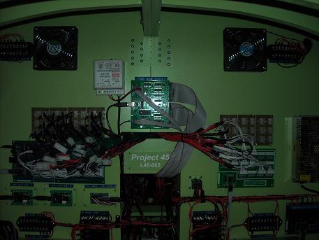
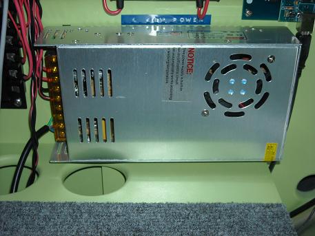
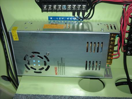
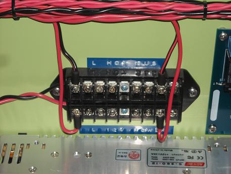
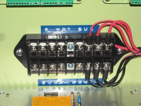
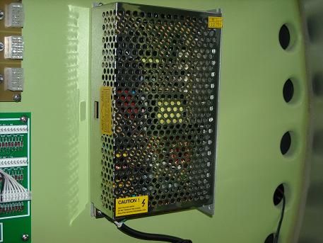
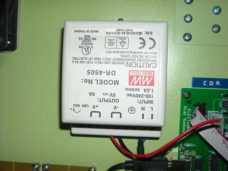
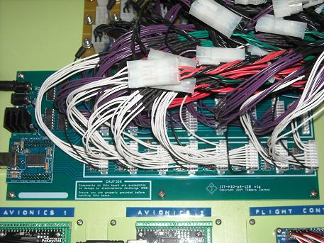
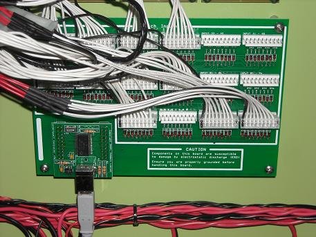
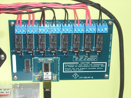
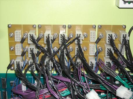
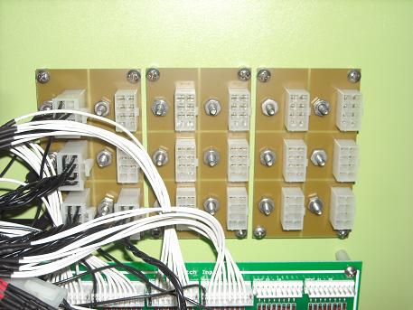
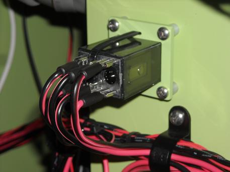
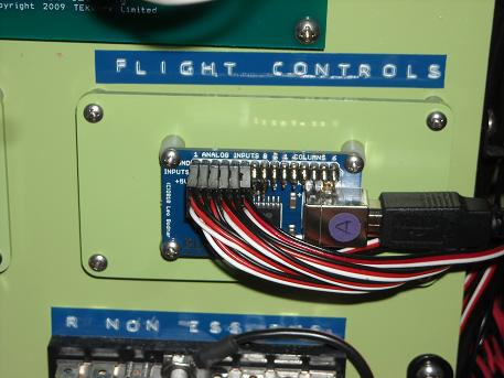
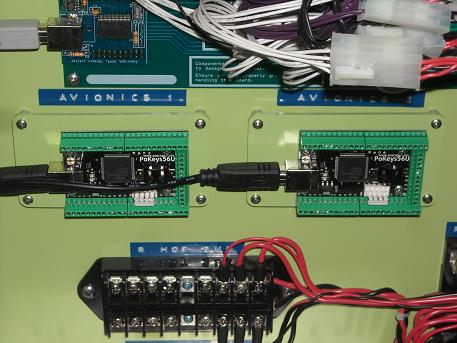
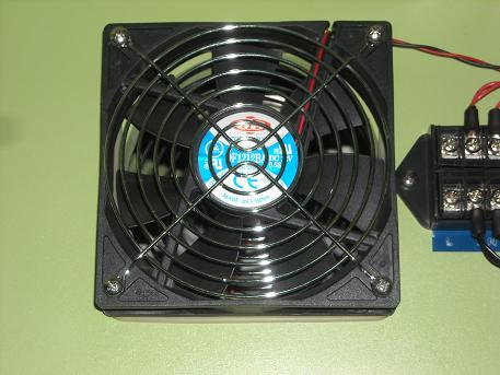
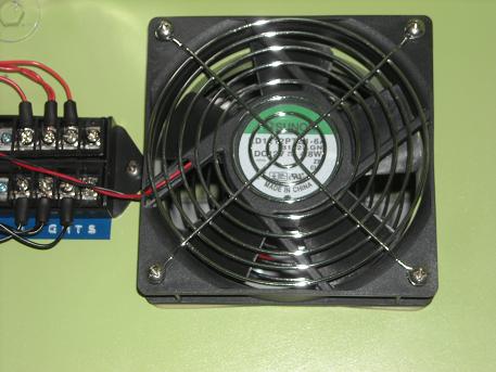
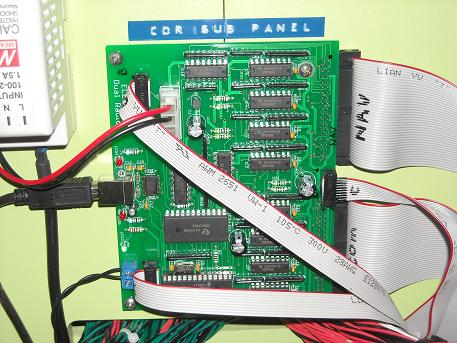
(Original thread started on 07-28-13 by Ron Rollo) This thread is to showcase the Project45 Avionics Bay and it's many components. One quick disclaimer: The information in this thread is not a rule but more of a guide. There is plenty of room for improvement in the way things are being done here and I welcome any suggestions and look forward to seeing what others are doing with their Lear45 builds in this department. We are still in the learning phase of this project and literally learning and sometimes changing things on the fly so to speak. With that said, the information in this thread is proven to work and seems to mesh well with all the related sub systems, so far anyway! Let's start with an overall photo and overview description of the firewall in the Avionics bay: The heart of the system are the Flight Deck Solution interface boards. I have three of them that handle inputs, outputs and relays. The reason why we absolutely love the FDS cards is because of the InterfaceIT software that enables us work magic with each switch and or LED individually. The InterfaceIT software lets us ad complicated software logic that would otherwise be nearly impossible to emulate using hardware logic. The other main feature in the L45-002 Avionics Bay is the dual 12volt power supply system and it's associated power buses. It is a true split and isolated system with everything on the port side of the aircraft being powered by the port 12v power supply and everything on the starboard side being powered by the starboard power supply. I have used Lear45 manuals to emulate the aircraft power supply system as close as I can without needing to commit myself if you know what I mean! To start with, I have a 12 outlet surge protector under the floor of the Avionics Bay where everything that needs "house current" 110V is plugged into it. Believe it or not, I don't have a single spare outlet in this thing: This surge protector powers: 4 Power Supplies (12 volt) 3 LCD screen monitors 2 Powered USB Hubs 1 Powered FDS card 1 Butt Kicker low frequency unit 1 Ventilation fan With the click of one switch on this surge protector, I can supply the needed power to the cockpit with the exception of some 5v low powered items from the computers: "Left 12 Volt Power Supply" This is a 30 AMP power supply with a cooling fan built in that runs if it senses that it is getting too hot. The lines from the power supply go directly to the Left ESS BUS and Left HOT BUS for distribution from there: I picked mine up off of eBay like this one: http://www.ebay.com/itm/12V-DC-30A-360W-Regulated-Switching-Power-Supply-/271143430382?pt=LH_DefaultDomain_0&hash=item3f216868ee "Right 12 Volt Power Supply" This is a 30 AMP power supply with a cooling fan built in that runs if it senses that it is getting too hot. The lines from the right side power supply go directly to the right ESS BUS and Right HOT BUS for distribution from there: I picked mine up off of eBay like this one: http://www.ebay.com/itm/12V-DC-30A-360W-Regulated-Switching-Power-Supply-/271143430382?pt=LH_DefaultDomain_0&hash=item3f216868ee "Left NON ESS BUS" This works perfectly to distribute power to the many places we need to send 12 volt power. If you look closely at the photo, you will see a grounding terminal running across the top and then there are places to connect the hot lines into the sides which are protected by fuses: The correct name for this part is "14 Gang ATO Fuse Block with Ground Bar" You can find it here on eBay: http://www.ebay.com/itm/14-Gang-ATO-Fuse-Block-with-Ground-Bar-/180527940278?pt=Boat_Parts_Accessories_Gear&hash=item2a084dc2b6&vxp=mtr "Right NON ESS BUS" This works perfectly to distribute power to the many places we need to send 12 volt power. If you look closely at the photo, you will see a grounding terminal running across the top and then there are places to connect the hot lines into the sides which are protected by fuses: The correct name for this part is "14 Gang ATO Fuse Block with Ground Bar" You can find it here on eBay: http://www.ebay.com/itm/14-Gang-ATO-Fuse-Block-with-Ground-Bar-/180527940278?pt=Boat_Parts_Accessories_Gear&hash=item2a084dc2b6&vxp=mtr (Please note that in both the left and right non essentials, I am using 2 and 3 amp fuse values. These fuse values may need to be adjusted in the future.) "Left HOT BUS" I have my overhead lighting and under the glare shield lighting tied into the hot bus. This way when I climb into a cold and dark cockpit I will at least be able to see what I am doing: It's real name: 9 Terminal at wire end CCTV Security Camera DC & AC Connector Splitter. You can find it on eBay here: http://www.ebay.com/itm/9-Terminal-at-wire-end-CCTV-Security-Camera-DC-AC-Connector-Splitter-/181145388196?pt=US_Surveillance_Cables_Adapters_Connectors&hash=item2a2d1b44a4 I took all mine apart and replaced the black wires with my red and black 18 gauge wires. "Right HOT BUS" I have my overhead lighting tied into the hot bus. This way when I climb into a cold and dark cockpit I will at least be able to see what I am doing: It's real name: 9 Terminal at wire end CCTV Security Camera DC & AC Connector Splitter. You can find it on eBay here: http://www.ebay.com/itm/9-Terminal-at-wire-end-CCTV-Security-Camera-DC-AC-Connector-Splitter-/181145388196?pt=US_Surveillance_Cables_Adapters_Connectors&hash=item2a2d1b44a4 I took all mine apart and replaced the black wires with my red and black 18 gauge wires. "24 Volt Power Supply" I currently do not have my 24 volt supply hooked up to anything. The plan is to use it to power the blowers to push air circulation through the vent system in the cockpit: The real name: 24 Volt Power Supply - 10 Amp Single Output PS1-240W-24 Here is where you will find it on eBay: http://www.ebay.com/itm/24-Volt-Power-Supply-10-Amp-Single-Output-PS1-240W-24-/380676643089?pt=LH_DefaultDomain_0&hash=item58a2189911 Beware that this is only 10amps and that you might require a more powerful 24 volt power supply depending on what your using it for. "5 Volt Power Supply" The only thing I have hooked into the 5 volt power supply to date is the Ruscool CDR (Clearance Delivery Radio) sub panel. I suppose if I wanted to I could use a resistor to drop down the voltage from 12 volts to 5 volts and just use the correct power supply: This is not the one I have in my build but if I had to buy one for just one small function like the CDR, this one would work: http://www.ebay.com/itm/MEAN-WELL-AC-DC-Power-Supply-Single-Output-5-Volt-5A-25W-/110778716532?pt=LH_DefaultDomain_0&hash=item19caed1174 "FDS-SYS4X High Capacity 64in/128out card" This is my main FDS card that handles the majority of all the switch functions on the lower MIP panels and glare shield. In addition to that, this card handles ALL of the LED lighting in the entire aircraft! Whenever possible, especially if you want to add software logic to a particular switch, make plans to hook it into one of your FDS cards so that you can take advantage of your InterfaceIT software: You can read more about the FDS-SYS4X card and it's abilities HERE "FDS-SYS2X High Capacity 128input card" This card handle the majority of all of the switch functions on the Center pedestal, TQ pedestal and SYS TEST panel. As you can see, I still have room for the several other items. Whenever possible, especially if you want to add software logic to a particular switch, make plans to hook it into one of your FDS cards so that you can take advantage of your InterfaceIT software: You can read more about the FDS-SYS2X card HERE "FDS-SYS-R1X Relay Board" (New Stand Alone Design 8 relays) This card handles all the switching from computer outputs to real hardware items like the stick shakers, Hobbs meter, Davtron Clocks and turning powered buses on and off that require real power. Most everything running into the relays are 12 volt power, however, anywhere that you need to open or close a line no matter if it is powered or not, this card will do the trick! No Power Supply is required, USB connection and our super simple XML import capabilities make this the "go to" piece for integrating those tougher devices: You can read more about the FDS-SYS-R1X card HERE "Project45 Grounding Terminals" These group of eight grounding terminals are designed to work with the FDS cards: As you may know, the FDS cards are designed to work in groups of eight for every single ground. So in other words, if you have eight switch functions, you will have eight signal wires which I color code as red lines and eight ground lines which I color code as black lines. You can either group those eight ground lines together at the back side of the panel to save some wire or run eight separate ground lines to the grounding terminals. From there, I use a plug to group the eight ground lines together and then I have one ground line coming out of that isolated block to the FDS pig tail. I opted to go this route so that I had more flexibility and control of grouping in the avionic bay rather than at the back side of the panels. However, there are a few exceptions where there was a perfect eight switch functions at the panel and I was able to run that group directly to the FDS pig tail and bypass the grounding terminal all together. This is why you might see several grounding terminal plugs empty. On the other hand, there were several places where I had one or as many as four lines still open and not connected to anything....YET. So what I did was spent a few extra minutes and dollars to create spare plugs at the FDS cards so that if later in the build I need to plug in say three switch functions, I can simply find a plug that has three signal lines and three ground lines. If you look close in the photo, you will see several of these either in us or opened plugs. You can order these Project45 Grounding terminals from me. I list them completed with plugs for $22 each. The Grounding Terminal thread can be found HERE "Project45 Grounding Terminals" These group of eight grounding terminals are designed to work with the FDS cards: You can order these Project45 Grounding terminals from me. I list them completed with plugs for $22 each. "Radio Shack double pole relay" Recently I needed an additional relay on the FDS relay card which only has eight outputs: So what I did was took the two stick shaker relay lines and hooked them into this double pole relay. Being that this is double pole relay means that the two sides of the relay are split and have nothing to do with each other except mimic one another when power is applied to it or taken away. Then I took a power line and ran it to one of the FDS relays and then to the radio shack relay. So when either I do a stick shaker test or the airplane goes into a stall, the software tells the FDS relay to close which sends power to the Radio Shack relay and it closes which in turn sends power to the two separate 12 volt stick shaker motors. All that to open up a spare relay on the FDS card for the CDR power line! "Leo Bodnar BU0836A" This card handles the main flight controls (Potentiometers): You can learn more or order your Leo Bodnar cards here: http://www.leobodnar.com/shop/index.php?main_page=product_info&cPath=85&products_id=204 I will say this, I had a pair of Leo Bodnar BU0836X cards that I was planning on using to handle all of the potentiometers. You can read about them and order them here: http://www.leobodnar.com/shop/index.php?main_page=product_info&cPath=85&products_id=180 I like them better than the BU0836A cards for several reasons. I still have one mounted to the bottom side of my TQ module that handles the throttles,flaps, spoilers, reversers and parking brake/emergency brake. The issue I was having was that they were both named the same thing and my computer was having an issue deciphering between the two. I tried to get some help from the staff at Leo Bodnar with not much luck. That's when I went ahead and ordered the BU0836A. After I got the second card that was obviously named differently from the first card, my computer was able to clearly see the two cards without conflict. "Pokeys56U cards" These are made by Prolabs and will run my RMUs and DUs. This is one of those areas in the sim that is still kind of up in the air as far as which way the main path will take us. For now, I have opted to use two Pokeys56U (the "U" means USB): If you would like to read more or order this item, go here: http://www.poscope.com/PoKeys56U (As you may know, the FGC, RMUs and DU's are full of encoders that will not work with the FDS cards which force us to use other cards in this area of the build. Pokeys, Leo Bodnar and Go Flight cards are some that will handle encoders.) "Left side Instrument Lighting BUS": It's real name: 9 Terminal at wire end CCTV Security Camera DC & AC Connector Splitter You can find it on eBay here: http://www.ebay.com/itm/9-Terminal-at-wire-end-CCTV-Security-Camera-DC-AC-Connector-Splitter-/181145388196?pt=US_Surveillance_Cables_Adapters_Connectors&hash=item2a2d1b44a4 I took all mine apart and replaced the black wires with my red and black 18 gauge wires. "Right side Instrument Lighting BUS": It's real name: 9 Terminal at wire end CCTV Security Camera DC & AC Connector Splitter You can find it on eBay here: http://www.ebay.com/itm/9-Terminal-at-wire-end-CCTV-Security-Camera-DC-AC-Connector-Splitter-/181145388196?pt=US_Surveillance_Cables_Adapters_Connectors&hash=item2a2d1b44a4 I took all mine apart and replaced the black wires with my red and black 18 gauge wires. "12 Volt Fan" This 12 volt fan is hard wired into a double pole AML Avionics switch for the port side of the aircraft: You can find these just about anywhere. "12 Volt Fan" This 12 volt fan is hard wired into a double pole AML Avionics switch for the starboard side of the aircraft: You can find these just about anywhere. "CDR Sub Panel" This board is made by Ruscool Electronics and is specifically designed to work them the Clearance Delivery Radio that they offer in partnership with Eric Tomlin:
(Original thread started on 07-28-13 by Ron Rollo) This thread is to showcase the Project45 Avionics Bay and it's many components. One quick disclaimer: The information in this thread is not a rule but more of a guide. There is plenty of room for improvement in the way things are being done here and I welcome any suggestions and look forward to seeing what others are doing with their Lear45 builds in this department. We are still in the learning phase of this project and literally learning and sometimes changing things on the fly so to speak. With that said, the information in this thread is proven to work and seems to mesh well with all the related sub systems, so far anyway! Let's start with an overall photo and overview description of the firewall in the Avionics bay: The heart of the system are the Flight Deck Solution interface boards. I have three of them that handle inputs, outputs and relays. The reason why we absolutely love the FDS cards is because of the InterfaceIT software that enables us work magic with each switch and or LED individually. The InterfaceIT software lets us ad complicated software logic that would otherwise be nearly impossible to emulate using hardware logic. The other main feature in the L45-002 Avionics Bay is the dual 12volt power supply system and it's associated power buses. It is a true split and isolated system with everything on the port side of the aircraft being powered by the port 12v power supply and everything on the starboard side being powered by the starboard power supply. I have used Lear45 manuals to emulate the aircraft power supply system as close as I can without needing to commit myself if you know what I mean! To start with, I have a 12 outlet surge protector under the floor of the Avionics Bay where everything that needs "house current" 110V is plugged into it. Believe it or not, I don't have a single spare outlet in this thing: This surge protector powers: 4 Power Supplies (12 volt) 3 LCD screen monitors 2 Powered USB Hubs 1 Powered FDS card 1 Butt Kicker low frequency unit 1 Ventilation fan With the click of one switch on this surge protector, I can supply the needed power to the cockpit with the exception of some 5v low powered items from the computers: "Left 12 Volt Power Supply" This is a 30 AMP power supply with a cooling fan built in that runs if it senses that it is getting too hot. The lines from the power supply go directly to the Left ESS BUS and Left HOT BUS for distribution from there: I picked mine up off of eBay like this one: http://www.ebay.com/itm/12V-DC-30A-360W-Regulated-Switching-Power-Supply-/271143430382?pt=LH_DefaultDomain_0&hash=item3f216868ee "Right 12 Volt Power Supply" This is a 30 AMP power supply with a cooling fan built in that runs if it senses that it is getting too hot. The lines from the right side power supply go directly to the right ESS BUS and Right HOT BUS for distribution from there: I picked mine up off of eBay like this one: http://www.ebay.com/itm/12V-DC-30A-360W-Regulated-Switching-Power-Supply-/271143430382?pt=LH_DefaultDomain_0&hash=item3f216868ee "Left NON ESS BUS" This works perfectly to distribute power to the many places we need to send 12 volt power. If you look closely at the photo, you will see a grounding terminal running across the top and then there are places to connect the hot lines into the sides which are protected by fuses: The correct name for this part is "14 Gang ATO Fuse Block with Ground Bar" You can find it here on eBay: http://www.ebay.com/itm/14-Gang-ATO-Fuse-Block-with-Ground-Bar-/180527940278?pt=Boat_Parts_Accessories_Gear&hash=item2a084dc2b6&vxp=mtr "Right NON ESS BUS" This works perfectly to distribute power to the many places we need to send 12 volt power. If you look closely at the photo, you will see a grounding terminal running across the top and then there are places to connect the hot lines into the sides which are protected by fuses: The correct name for this part is "14 Gang ATO Fuse Block with Ground Bar" You can find it here on eBay: http://www.ebay.com/itm/14-Gang-ATO-Fuse-Block-with-Ground-Bar-/180527940278?pt=Boat_Parts_Accessories_Gear&hash=item2a084dc2b6&vxp=mtr (Please note that in both the left and right non essentials, I am using 2 and 3 amp fuse values. These fuse values may need to be adjusted in the future.) "Left HOT BUS" I have my overhead lighting and under the glare shield lighting tied into the hot bus. This way when I climb into a cold and dark cockpit I will at least be able to see what I am doing: It's real name: 9 Terminal at wire end CCTV Security Camera DC & AC Connector Splitter. You can find it on eBay here: http://www.ebay.com/itm/9-Terminal-at-wire-end-CCTV-Security-Camera-DC-AC-Connector-Splitter-/181145388196?pt=US_Surveillance_Cables_Adapters_Connectors&hash=item2a2d1b44a4 I took all mine apart and replaced the black wires with my red and black 18 gauge wires. "Right HOT BUS" I have my overhead lighting tied into the hot bus. This way when I climb into a cold and dark cockpit I will at least be able to see what I am doing: It's real name: 9 Terminal at wire end CCTV Security Camera DC & AC Connector Splitter. You can find it on eBay here: http://www.ebay.com/itm/9-Terminal-at-wire-end-CCTV-Security-Camera-DC-AC-Connector-Splitter-/181145388196?pt=US_Surveillance_Cables_Adapters_Connectors&hash=item2a2d1b44a4 I took all mine apart and replaced the black wires with my red and black 18 gauge wires. "24 Volt Power Supply" I currently do not have my 24 volt supply hooked up to anything. The plan is to use it to power the blowers to push air circulation through the vent system in the cockpit: The real name: 24 Volt Power Supply - 10 Amp Single Output PS1-240W-24 Here is where you will find it on eBay: http://www.ebay.com/itm/24-Volt-Power-Supply-10-Amp-Single-Output-PS1-240W-24-/380676643089?pt=LH_DefaultDomain_0&hash=item58a2189911 Beware that this is only 10amps and that you might require a more powerful 24 volt power supply depending on what your using it for. "5 Volt Power Supply" The only thing I have hooked into the 5 volt power supply to date is the Ruscool CDR (Clearance Delivery Radio) sub panel. I suppose if I wanted to I could use a resistor to drop down the voltage from 12 volts to 5 volts and just use the correct power supply: This is not the one I have in my build but if I had to buy one for just one small function like the CDR, this one would work: http://www.ebay.com/itm/MEAN-WELL-AC-DC-Power-Supply-Single-Output-5-Volt-5A-25W-/110778716532?pt=LH_DefaultDomain_0&hash=item19caed1174 "FDS-SYS4X High Capacity 64in/128out card" This is my main FDS card that handles the majority of all the switch functions on the lower MIP panels and glare shield. In addition to that, this card handles ALL of the LED lighting in the entire aircraft! Whenever possible, especially if you want to add software logic to a particular switch, make plans to hook it into one of your FDS cards so that you can take advantage of your InterfaceIT software: You can read more about the FDS-SYS4X card and it's abilities HERE "FDS-SYS2X High Capacity 128input card" This card handle the majority of all of the switch functions on the Center pedestal, TQ pedestal and SYS TEST panel. As you can see, I still have room for the several other items. Whenever possible, especially if you want to add software logic to a particular switch, make plans to hook it into one of your FDS cards so that you can take advantage of your InterfaceIT software: You can read more about the FDS-SYS2X card HERE "FDS-SYS-R1X Relay Board" (New Stand Alone Design 8 relays) This card handles all the switching from computer outputs to real hardware items like the stick shakers, Hobbs meter, Davtron Clocks and turning powered buses on and off that require real power. Most everything running into the relays are 12 volt power, however, anywhere that you need to open or close a line no matter if it is powered or not, this card will do the trick! No Power Supply is required, USB connection and our super simple XML import capabilities make this the "go to" piece for integrating those tougher devices: You can read more about the FDS-SYS-R1X card HERE "Project45 Grounding Terminals" These group of eight grounding terminals are designed to work with the FDS cards: As you may know, the FDS cards are designed to work in groups of eight for every single ground. So in other words, if you have eight switch functions, you will have eight signal wires which I color code as red lines and eight ground lines which I color code as black lines. You can either group those eight ground lines together at the back side of the panel to save some wire or run eight separate ground lines to the grounding terminals. From there, I use a plug to group the eight ground lines together and then I have one ground line coming out of that isolated block to the FDS pig tail. I opted to go this route so that I had more flexibility and control of grouping in the avionic bay rather than at the back side of the panels. However, there are a few exceptions where there was a perfect eight switch functions at the panel and I was able to run that group directly to the FDS pig tail and bypass the grounding terminal all together. This is why you might see several grounding terminal plugs empty. On the other hand, there were several places where I had one or as many as four lines still open and not connected to anything....YET. So what I did was spent a few extra minutes and dollars to create spare plugs at the FDS cards so that if later in the build I need to plug in say three switch functions, I can simply find a plug that has three signal lines and three ground lines. If you look close in the photo, you will see several of these either in us or opened plugs. You can order these Project45 Grounding terminals from me. I list them completed with plugs for $22 each. The Grounding Terminal thread can be found HERE "Project45 Grounding Terminals" These group of eight grounding terminals are designed to work with the FDS cards: You can order these Project45 Grounding terminals from me. I list them completed with plugs for $22 each. "Radio Shack double pole relay" Recently I needed an additional relay on the FDS relay card which only has eight outputs: So what I did was took the two stick shaker relay lines and hooked them into this double pole relay. Being that this is double pole relay means that the two sides of the relay are split and have nothing to do with each other except mimic one another when power is applied to it or taken away. Then I took a power line and ran it to one of the FDS relays and then to the radio shack relay. So when either I do a stick shaker test or the airplane goes into a stall, the software tells the FDS relay to close which sends power to the Radio Shack relay and it closes which in turn sends power to the two separate 12 volt stick shaker motors. All that to open up a spare relay on the FDS card for the CDR power line! "Leo Bodnar BU0836A" This card handles the main flight controls (Potentiometers): You can learn more or order your Leo Bodnar cards here: http://www.leobodnar.com/shop/index.php?main_page=product_info&cPath=85&products_id=204 I will say this, I had a pair of Leo Bodnar BU0836X cards that I was planning on using to handle all of the potentiometers. You can read about them and order them here: http://www.leobodnar.com/shop/index.php?main_page=product_info&cPath=85&products_id=180 I like them better than the BU0836A cards for several reasons. I still have one mounted to the bottom side of my TQ module that handles the throttles,flaps, spoilers, reversers and parking brake/emergency brake. The issue I was having was that they were both named the same thing and my computer was having an issue deciphering between the two. I tried to get some help from the staff at Leo Bodnar with not much luck. That's when I went ahead and ordered the BU0836A. After I got the second card that was obviously named differently from the first card, my computer was able to clearly see the two cards without conflict. "Pokeys56U cards" These are made by Prolabs and will run my RMUs and DUs. This is one of those areas in the sim that is still kind of up in the air as far as which way the main path will take us. For now, I have opted to use two Pokeys56U (the "U" means USB): If you would like to read more or order this item, go here: http://www.poscope.com/PoKeys56U (As you may know, the FGC, RMUs and DU's are full of encoders that will not work with the FDS cards which force us to use other cards in this area of the build. Pokeys, Leo Bodnar and Go Flight cards are some that will handle encoders.) "Left side Instrument Lighting BUS": It's real name: 9 Terminal at wire end CCTV Security Camera DC & AC Connector Splitter You can find it on eBay here: http://www.ebay.com/itm/9-Terminal-at-wire-end-CCTV-Security-Camera-DC-AC-Connector-Splitter-/181145388196?pt=US_Surveillance_Cables_Adapters_Connectors&hash=item2a2d1b44a4 I took all mine apart and replaced the black wires with my red and black 18 gauge wires. "Right side Instrument Lighting BUS": It's real name: 9 Terminal at wire end CCTV Security Camera DC & AC Connector Splitter You can find it on eBay here: http://www.ebay.com/itm/9-Terminal-at-wire-end-CCTV-Security-Camera-DC-AC-Connector-Splitter-/181145388196?pt=US_Surveillance_Cables_Adapters_Connectors&hash=item2a2d1b44a4 I took all mine apart and replaced the black wires with my red and black 18 gauge wires. "12 Volt Fan" This 12 volt fan is hard wired into a double pole AML Avionics switch for the port side of the aircraft: You can find these just about anywhere. "12 Volt Fan" This 12 volt fan is hard wired into a double pole AML Avionics switch for the starboard side of the aircraft: You can find these just about anywhere. "CDR Sub Panel" This board is made by Ruscool Electronics and is specifically designed to work them the Clearance Delivery Radio that they offer in partnership with Eric Tomlin:
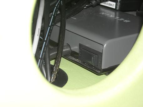
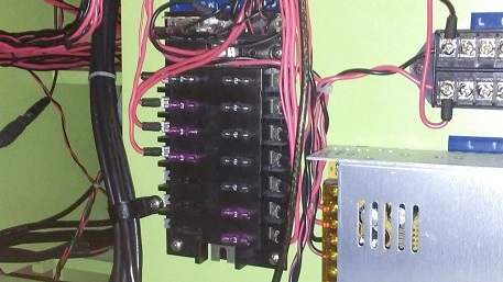
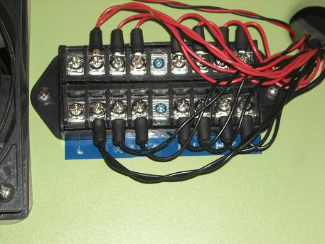
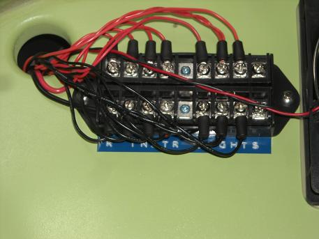
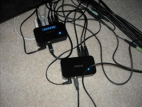
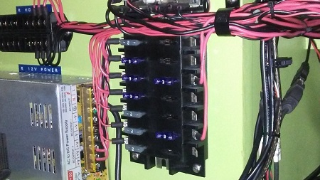
(Posted by Ron Rollo on 07-28-13) CONTINUATION: "Dlink 2.0 7 port Powered USB hubs" If your computers are more than 15 feet away from your powered devices, theoretically you will want powered USB hubs to boost the signal. Also, this will help reduce the mess of cables that you will have running back to the computers: However, after about a year of fooling around with two of the same Dlink USB hubs, I am still having issues with conflicting signals. You can read about the issue HERE At this point, I would recommend either finding a 10 port powered USB hub or two different kinds of powered USB hubs. "Leo Bodnar BU0836X" Last but not least and not exactly in the Avionics bay is the TQ module interface card. I decided to mount it directly to the bottom side of the TQ module to make it plug and play. More so that it is easier to pull in and out of the TQ pedestal: To read up or order this card, go here: http://www.leobodnar.com/products/BU0836X/ If you have any questions on anything, please feel free to post here and I will be happy to expand on whatever it is. (Posted by Alan Norris on 07-29-13) Super nice Ron. I love the neatness of all your wiring. When you say you have the left and right side split, how do you achieve that with the FDS cards? Also have you got your left and right Avionics switches working as they should or is that something that JET45 needs to handle? Thanks for sharing and setting the standard for good layout design and wire routing. (Posted by Eric Tomlin on 07-29-13) Great run thru Ron. Alan, the Interfacing isn't split L/R. Also, JET45 hasn't yet implemented L/R avionics buses yet, but hopefully will in a Systems software. (Posted by Ron Rollo on 07-29-13) Alan, it's not so much that the FDS cards and functions are split. What I mean is that the real hardware, lights, fans, clocks, stick shakers, etc. are split. And if possible, the FDS cards can help control that. As an example, the left Avionics switch as you know turn the avionics on for the whole plane because that is what we are stuck with due to the limitations in FS9 and FSX. However, both of my Avionics switches are double pole switches. One side of each switch is wired to the FDS card and the other side is wired to those 12 volt fans that you see in the fire wall. So when I hit he left Avionics switch, all of the avionics come on in the whole plane, the LED indicator light in that AML switch comes on and the left avionics cooling fan comes on. When I hit the right avionics switch, only the LED in that switch comes on and the right avionics cooling fan comes on. That is one of the best examples of making it appear as if there is a split system when in reality it is not. But the power to each of those fans is certainly split and coming from two different 12 volt power supplies! (Posted by Randy Buchanan on 08-02-13) Wow Ron, as always, such nice work! As I was looking at these pictures I saw some, what I would call car type fuses and it occurred to me that all of this wiring could or does go through the left and right circuit breaker panels in the plane. I was planing a temporary circuit breaker panel in my cockpit, but I know there are some members who think it would be cool if those circuit breaker panels worked as well. Ron, where you thinking of wiring some of the hundreds of little pull circuit breaker switches? (Posted by Ron Rollo on 02-12-14) Hey Randy, sorry, I must have missed this question. Your talking about a lot of work and more importantly, a lot of pre-planning which I did not do because I never intended to go this route. My breakers will be dummies only which means we will be able to pull them to simulate cutting power to a specific component in the aircraft. If you or anyone wants working breakers, you better plan on having them in your sim from the beginning because everything will be ran to and from the breakers. As you can see form the post above, I have working breakers for real hardware that is receiving 12 volt power. If you take a close look at the things listed on the circuit breaker panels, 90% of the items are sim items and are ran via software. So I am not sure how you would go about hard wiring breaker panels without needing to create software like (Jet45) to implement it. In other words, this is a lot of work for very little return. (Posted by Mark Speechley on 10-06-14) I have my sim in bits at the moment getting the wiring right. I've used Ron's wonderful example of how he has set out his electrical distribution. I note though that on his Right and Left Non Essential Bus's that he has a mixture of fuses. So a couple of questions popped up after talking to an electrician. 1/ Are some of those amp fuses too high, for example, to protect the panel LED's? Would 1 amp fuses be better? 2/ If 1 amp fuses are too high then we need to get into the cylindrical 3AG 500mA quick blow fuses or less.? http://www.jaycar.com.au/productView.asp?ID=SF2188&form=CAT2&SUBCATID=969#1 This creates a problem where you need to find a multiple holder for this type of fuse. (Posted by Ron Rollo on 10-06-14) Hey Mark, I currently am using 2 and 3 AMP fuses but I am still not sure if there is any protection of the wires. DonnyRay was telling me a few years back that fuses are not designed to protect the panel or gizmo receiving power. (In most cases, something has gone wrong with it anyway if it is blowing fuses) Instead, fuses are designed to protect the wiring from burning up and causing a fire. As an example, my AC stopped working in my police car last month. It turns out that the 10amp fuse to the compressor was blown. They replaced the 10amp fuse and the AC worked again....for 1 minute. Then they replaced the second blown fuse with a 20amp fuse. This time the AC worked.....for 2 minutes! If they were to take a nail to cross the fuse block, it would give the wiring no protection and the AC would work.........until the car caught fire. In our case, the chance that the LEDs/resistors can do anything to cause a fire or hot wire is slim to none. A more likely scenario would be a short in the ground to the hot side of the back lighting clad, this is where a fuse would come in handy. I'm not a electrical wizard by no means and if I were, I would give you a mathematical answer to what size fuse you need. But I think it is safe to say that the fuse needs to be strong enough to let the power flow but not so strong that if things get too hot, the wiring melts. (Posted by Will Sasse on 10-06-14) I wonder if we need another fuse block in our circuits at all? It may just be an extra complication? PC motherboards have their own fuses, as should the 'store bought' self-powered expansion cards (FDS, PoKeys, Arduino, etc). Normally, there is no fuse to protect a light bulb, as Ron says it's there to prevent a wiring fire. The voltage and current flow on our sims should be covered by the on-board fuses of each powered card... unless you've bought unprotected power supplies from somewhere cheap? I am no expert on this matter, and am happy to be corrected... (Posted by Mark Speechley on 10-06-14) Good points Will. However should these cards have inbuilt fuses and they blow then we would usually have to buy replacement cards. If we are to protect the sim from external power spikes then I assume good quality power boards with surge protection should be sufficient. However if we are to protect the sim from internal faults as pointed out by Ron ( and by default DonnyRay ) then a very low amp fuse would be further insurance. I have had some wires heating up and starting to melt so it does happen. I even have a hand held non contact thermometer to check temps but with all the wiring is not practical. I have even considered ......overkill...... but a hand held thermal imager. This is a staple item for electricians now looking for shorts and even has other uses such as looking for wall water leaks. I could use it for thermal imaging lesions under the skin of patients , (however a much higher resolution unit would be needed for that). Fluke and FLIR are very good brands if you have some spare cash laying around. Interesting topic and all input is important as I am finishing off the purchasing of items. I want to get the sim up and flying again. P3D 2.4 and ORBX global 1.3 is passing me by! (Posted by Ron Rollo on 06-02-17) Mark Speechley brought up a great point a couple of years ago in reference to fuses and proper protection. Initially, some of my fuses were 10 AMP fuse which would have been of no use in protecting anything but themselves. This is the kind of stuff that DonnyRay Jones lives for and one day maybe he can help us figure our the correct value of fuses that we should use in our NON Essential terminal blocks. But for now, what I have done is replaced all of my fuses with 2 and 3 AMP fuses depending on the gauge wire I have coming into the terminals. The 22 gauge wires have 2 AMP fuses and the 18 gauge wires now have 3 AMP fuses. I have several 1 AMP ATC/ATO fuses on order from here: http://www.ebay.com/itm/25-Pack-1-AMP-ATC-ATO-STANDARD-Regular-FUSE-BLADE-1A-CAR-TRUCK-BOAT-MARINE-RV-US-/222315896103?hash=item33c30f5d27:g:1lYAAOSwImRYK1b8 I am going to do some experimenting over the next several days once the 1 AMP fuses arrive. I expect to blow some of them especially with things like the stick shakers running. I can't imagine that blowing a fuse will hurt anything except for the fuse so this should be interesting. With all this said, Will is right, the FDS cards have built in fuses that protect the SYS Interface cards. Here are a few photos of the left and right NON Essential blocks with only 2 and 3 AMP fuses as of this time: I will report back and let you know what my findings are after I do some testing. Mark, I know you will be especially interested! (Posted by Ron Rollo on 07-28-13) CONTINUATION: "Dlink 2.0 7 port Powered USB hubs" If your computers are more than 15 feet away from your powered devices, theoretically you will want powered USB hubs to boost the signal. Also, this will help reduce the mess of cables that you will have running back to the computers: However, after about a year of fooling around with two of the same Dlink USB hubs, I am still having issues with conflicting signals. You can read about the issue HERE At this point, I would recommend either finding a 10 port powered USB hub or two different kinds of powered USB hubs. "Leo Bodnar BU0836X" Last but not least and not exactly in the Avionics bay is the TQ module interface card. I decided to mount it directly to the bottom side of the TQ module to make it plug and play. More so that it is easier to pull in and out of the TQ pedestal: To read up or order this card, go here: http://www.leobodnar.com/products/BU0836X/ If you have any questions on anything, please feel free to post here and I will be happy to expand on whatever it is. (Posted by Alan Norris on 07-29-13) Super nice Ron. I love the neatness of all your wiring. When you say you have the left and right side split, how do you achieve that with the FDS cards? Also have you got your left and right Avionics switches working as they should or is that something that JET45 needs to handle? Thanks for sharing and setting the standard for good layout design and wire routing. (Posted by Eric Tomlin on 07-29-13) Great run thru Ron. Alan, the Interfacing isn't split L/R. Also, JET45 hasn't yet implemented L/R avionics buses yet, but hopefully will in a Systems software. (Posted by Ron Rollo on 07-29-13) Alan, it's not so much that the FDS cards and functions are split. What I mean is that the real hardware, lights, fans, clocks, stick shakers, etc. are split. And if possible, the FDS cards can help control that. As an example, the left Avionics switch as you know turn the avionics on for the whole plane because that is what we are stuck with due to the limitations in FS9 and FSX. However, both of my Avionics switches are double pole switches. One side of each switch is wired to the FDS card and the other side is wired to those 12 volt fans that you see in the fire wall. So when I hit he left Avionics switch, all of the avionics come on in the whole plane, the LED indicator light in that AML switch comes on and the left avionics cooling fan comes on. When I hit the right avionics switch, only the LED in that switch comes on and the right avionics cooling fan comes on. That is one of the best examples of making it appear as if there is a split system when in reality it is not. But the power to each of those fans is certainly split and coming from two different 12 volt power supplies! (Posted by Randy Buchanan on 08-02-13) Wow Ron, as always, such nice work! As I was looking at these pictures I saw some, what I would call car type fuses and it occurred to me that all of this wiring could or does go through the left and right circuit breaker panels in the plane. I was planing a temporary circuit breaker panel in my cockpit, but I know there are some members who think it would be cool if those circuit breaker panels worked as well. Ron, where you thinking of wiring some of the hundreds of little pull circuit breaker switches? (Posted by Ron Rollo on 02-12-14) Hey Randy, sorry, I must have missed this question. Your talking about a lot of work and more importantly, a lot of pre-planning which I did not do because I never intended to go this route. My breakers will be dummies only which means we will be able to pull them to simulate cutting power to a specific component in the aircraft. If you or anyone wants working breakers, you better plan on having them in your sim from the beginning because everything will be ran to and from the breakers. As you can see form the post above, I have working breakers for real hardware that is receiving 12 volt power. If you take a close look at the things listed on the circuit breaker panels, 90% of the items are sim items and are ran via software. So I am not sure how you would go about hard wiring breaker panels without needing to create software like (Jet45) to implement it. In other words, this is a lot of work for very little return. (Posted by Mark Speechley on 10-06-14) I have my sim in bits at the moment getting the wiring right. I've used Ron's wonderful example of how he has set out his electrical distribution. I note though that on his Right and Left Non Essential Bus's that he has a mixture of fuses. So a couple of questions popped up after talking to an electrician. 1/ Are some of those amp fuses too high, for example, to protect the panel LED's? Would 1 amp fuses be better? 2/ If 1 amp fuses are too high then we need to get into the cylindrical 3AG 500mA quick blow fuses or less.? http://www.jaycar.com.au/productView.asp?ID=SF2188&form=CAT2&SUBCATID=969#1 This creates a problem where you need to find a multiple holder for this type of fuse. (Posted by Ron Rollo on 10-06-14) Hey Mark, I currently am using 2 and 3 AMP fuses but I am still not sure if there is any protection of the wires. DonnyRay was telling me a few years back that fuses are not designed to protect the panel or gizmo receiving power. (In most cases, something has gone wrong with it anyway if it is blowing fuses) Instead, fuses are designed to protect the wiring from burning up and causing a fire. As an example, my AC stopped working in my police car last month. It turns out that the 10amp fuse to the compressor was blown. They replaced the 10amp fuse and the AC worked again....for 1 minute. Then they replaced the second blown fuse with a 20amp fuse. This time the AC worked.....for 2 minutes! If they were to take a nail to cross the fuse block, it would give the wiring no protection and the AC would work.........until the car caught fire. In our case, the chance that the LEDs/resistors can do anything to cause a fire or hot wire is slim to none. A more likely scenario would be a short in the ground to the hot side of the back lighting clad, this is where a fuse would come in handy. I'm not a electrical wizard by no means and if I were, I would give you a mathematical answer to what size fuse you need. But I think it is safe to say that the fuse needs to be strong enough to let the power flow but not so strong that if things get too hot, the wiring melts. (Posted by Will Sasse on 10-06-14) I wonder if we need another fuse block in our circuits at all? It may just be an extra complication? PC motherboards have their own fuses, as should the 'store bought' self-powered expansion cards (FDS, PoKeys, Arduino, etc). Normally, there is no fuse to protect a light bulb, as Ron says it's there to prevent a wiring fire. The voltage and current flow on our sims should be covered by the on-board fuses of each powered card... unless you've bought unprotected power supplies from somewhere cheap? I am no expert on this matter, and am happy to be corrected... (Posted by Mark Speechley on 10-06-14) Good points Will. However should these cards have inbuilt fuses and they blow then we would usually have to buy replacement cards. If we are to protect the sim from external power spikes then I assume good quality power boards with surge protection should be sufficient. However if we are to protect the sim from internal faults as pointed out by Ron ( and by default DonnyRay ) then a very low amp fuse would be further insurance. I have had some wires heating up and starting to melt so it does happen. I even have a hand held non contact thermometer to check temps but with all the wiring is not practical. I have even considered ......overkill...... but a hand held thermal imager. This is a staple item for electricians now looking for shorts and even has other uses such as looking for wall water leaks. I could use it for thermal imaging lesions under the skin of patients , (however a much higher resolution unit would be needed for that). Fluke and FLIR are very good brands if you have some spare cash laying around. Interesting topic and all input is important as I am finishing off the purchasing of items. I want to get the sim up and flying again. P3D 2.4 and ORBX global 1.3 is passing me by! (Posted by Ron Rollo on 06-02-17) Mark Speechley brought up a great point a couple of years ago in reference to fuses and proper protection. Initially, some of my fuses were 10 AMP fuse which would have been of no use in protecting anything but themselves. This is the kind of stuff that DonnyRay Jones lives for and one day maybe he can help us figure our the correct value of fuses that we should use in our NON Essential terminal blocks. But for now, what I have done is replaced all of my fuses with 2 and 3 AMP fuses depending on the gauge wire I have coming into the terminals. The 22 gauge wires have 2 AMP fuses and the 18 gauge wires now have 3 AMP fuses. I have several 1 AMP ATC/ATO fuses on order from here: I am going to do some experimenting over the next several days once the 1 AMP fuses arrive. I expect to blow some of them especially with things like the stick shakers running. I can't imagine that blowing a fuse will hurt anything except for the fuse so this should be interesting. With all this said, Will is right, the FDS cards have built in fuses that protect the SYS Interface cards. Here are a few photos of the left and right NON Essential blocks with only 2 and 3 AMP fuses as of this time: I will report back and let you know what my findings are after I do some testing. Mark, I know you will be especially interested!Avionics Bay and Components By Project45
![]()

![]()

2017-10-10