


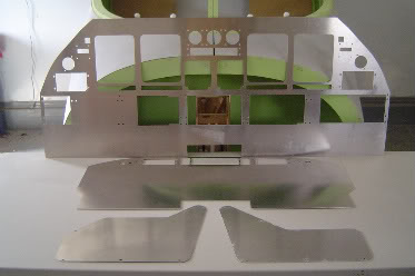
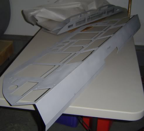
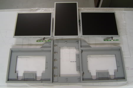
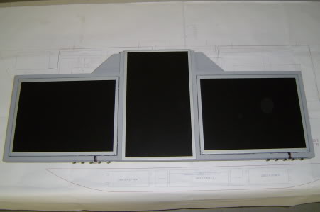
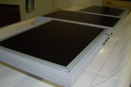
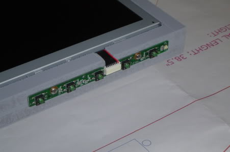
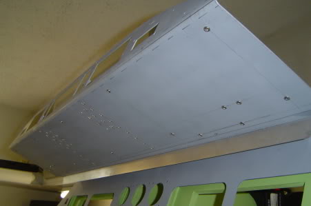
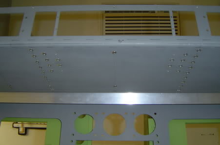
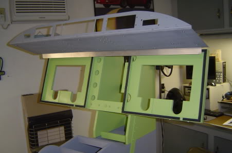
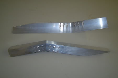
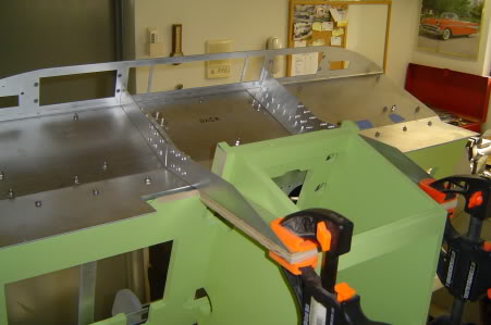
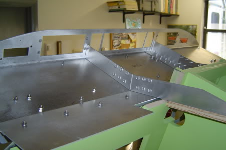
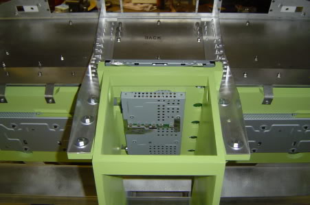
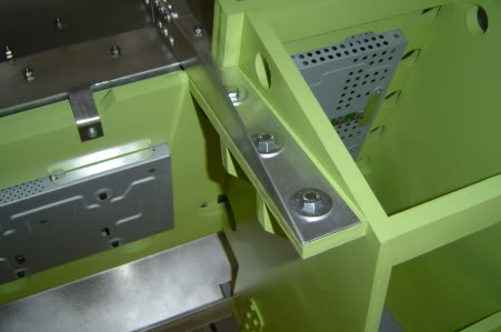
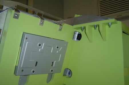
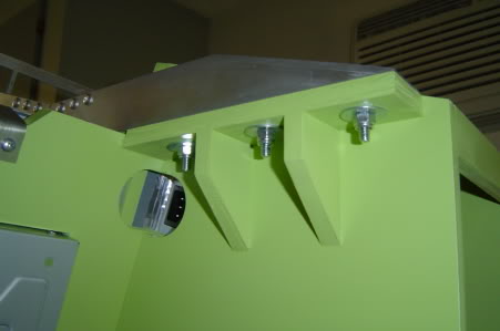
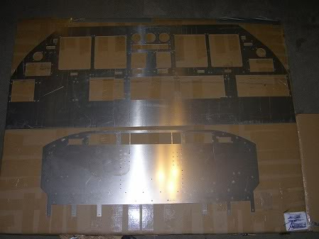
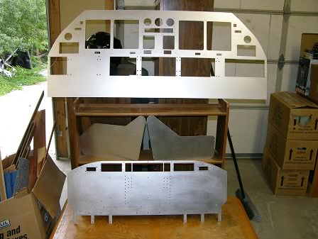
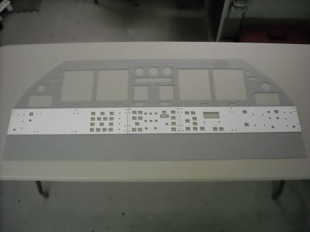
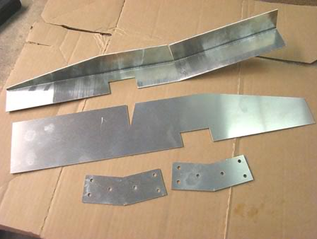
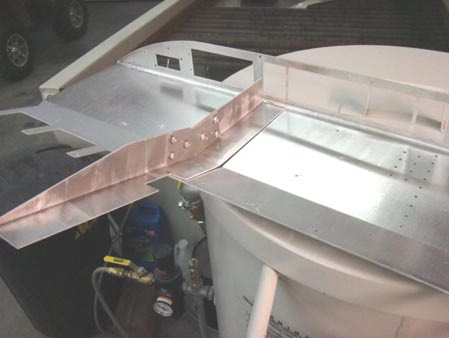
(Original thread started on 03-04-09 by Eric Tomlin) Just an update on both mine and Ron's projects. We have today taken delivery of a prototype LJ40/45 MIP, Glare Shield, and TQ Pedestal Covers from one of our new members here, Tom Goldberg. Tom made these using a waterjet machine and 1/16th inch aluminum sheet stock. Once we get the proper angles and bends placed in them we will make them available to other Hangar45 members: I also want to point out that the piece shown here has some finish work that Ron and I elected to do ourselves and another very important point is that this piece is designed for accepting the panels as I have designed them for mine and Ron's project since they are virtually identical in regards to panels and other hardware. This product is perfect for those with a CNC building their own panels, but you may need to create a MIP file specifically for your own panel design and send that to Tom, as this design likely wont fit other vendor's panels that may be coming soon from FDS, etc. without some mods, just so you know (and they likely will have their own version of this anyway). (Posted by Ron Rollo on 03-04-09) I told a few of you we had a surprise coming soon. This is it! Tom Goldberg, one of our newest members is the guy you need to make contact with if you are interested in aluminum parts. Tom created these four parts (times 2) for Eric and I in just a matter of a day based on our CAD drawings. Tom has the ability to cut many different materials on a large 4'X8' cutting table if you supply him with the CAD drawings. Here are a few photos of the aluminum parts fresh from the metal brake shop here in Jacksonville. Thanks to Tom for these great parts! Here in the near future I will take some photos for everyone to illustrate exactly where the breaks need to be and at what angles: (Posted by Jack jethomasjr on 03-05-09) First let me say, very nice. Waterjet cutting is the way to go. If you have any drawing in Solidworks, CAD, or CATIA, just send them in DXF form and the rest is history. Now that I see the picture here I can tell you that while I was in Lear 45 maintenance initial, the instructor took us downstairs and into a room with many Lear 45 parts. This MIP was one of them and this is exactly how it is. One flat piece of metal. Everything else is installed once this is installed in the aircraft. Ron, you were right, it was AC S/N 004 that had the incident. (Posted by Ron Rollo on 03-05-09) Hi Jack, funny how 004 is always the trouble maker! And thank you for sharing your thoughts and knowledge on the MIP structure. The build process I have in mind should be close to how the real deal is assembled. I can't wait to work with these pieces and post some more pictures to give everyone some ideas. I spent the past few days working on the MIP Backer support. I had a solid idea in mind but it took about three attempts to get it to the stage pictured below. It is made of half inch MDF and is designed to hold two 15.6" standard LCD's and one 15" wide view in portrait mode. This setup is the only one known that covers everything that needs to be covered, keeps the MIP at 100% to scale AND allows everything to be modeled such as the GWPS FAIL, Davtron clocks, Audio Control Panels and the AOA gauges without being impeded on by the LCD monitors. I have to thank Vince and his brilliant work on the Display Units and RMU's. He has designed all of the buttons to be integrated into the units themselves. This means it does not matter if there is LCD screen behind the lower parts of these units or not. However, I will tell you that if you want to go another route and use larger mechanical buttons that require more room behind the Display Units, you can use 15" wide screens on both sides. The only catch is you either sacrifice the GWPS FAIL or you have to move it further outboard, which means the MIP is a little out of scale. Pictured below is the first MIP Backer support that I have built. This one will be Eric's who will be picking it up on 05-25-09 along with a bunch of other parts. (LCD's not included): While working on this MIP backer unit, I paid special attention to strength, ventilation, wiring and sound dampening issues. Not pictured yet, I plan to put 1/8th inch thick, half inch wide rubber or foam around all of the LCD's to keep the aluminum MIP from rattling against the LCD bezels. Last but not least, I made a "JIG" of the main parts so that I can easily duplicate this unit for myself and other Hangar45 members if need be. By the way, you will be able to reach "under the dash" to access these buttons. The buttons for the center LCD screen will be mounted to the back side of it which will make it a little harder to get to, but still possible. The cool thing is once your settings are correct, you don't ever have to mess with them again. When you turn the computers off, the LCD's go to sleep too! (Posted by Ron Rollo on 07-03-09) This next bit of information covers the Glare Shield and the major components that hold it up in place. There are two main supports that run off of the Glare Shield that are made of 1.5 inch "L" or Angle aluminum. I used rivets to hold the supports to the glare shield. By the way, I mapped out every A/C fastener AKA rivets in my case and all the screws on the bottom side of the Glare Shield. I am in the process of updating the master DXF file so for those of you who are planning on getting the Aluminum set from Tom Goldberg, you won't have to worry about drilling the 50 holes manually. For those of you who already have the set, we will send you a 1 to 1 PDF file so that you can manually drill them like I did. To date, I have it temporally attached in place and I am more than happy with the strength of it so far. I am still planning on making some brackets for the far left and right ends. Here are some pictures of the work completed this week: A floating glare shield! The angle of the MIP from the bottom of the Glare Shield is 90 degrees. As my set up sits in this picture, it's a tad over, 91 degrees. This is fine because by the time I add the weight of the panels, cover, and sun shades, it will probably pull it down to 90 degrees on the button: If you pay close attention to all the screws under the Glare Shield, you will be able to find 10 of them that are meant to hold it up from the bottom. But in this case, they are dummies: A great picture of the numerous rivets under the FGC. I am going to fill them in with JB Weld an sand them down to make them look like the real part: One of the neat things about the overall design of the MIP structure is that the aluminum MIP face can easily be removed for LCD maintenance without taking everything apart: The Glare Shield supports by themselves. Each one uses 12 rivets at the point that they are bent at 18 degrees: I still have to finalize the attachment points on the rear end of the supports. Also notice that the top 3 inches of center LCD screen fits between these two brackets: You can clearly see all of the rivets and dummy screw bolts on the back side of the Glare Shield here. Some of these may come in handy to hold misc. components under the Glare Shield Cover. Here are some "behind the scenes" images of how I attached the Glare shied to the MIP Backer Support Tower with the LCD's in place. It is surprisingly strong! Strong enough that if someone where to reach out and steady themselves while getting in or out, it won't budge! All three LCD's sitting pretty from behind: Good picture of the Glare Shield Support wings with the three bolts per side: Don't forget about the access holes for the power plugs and VGA plugs! Another great pictures of the support wings from the under side:
(Original thread started on 03-04-09 by Eric Tomlin) Just an update on both mine and Ron's projects. We have today taken delivery of a prototype LJ40/45 MIP, Glare Shield, and TQ Pedestal Covers from one of our new members here, Tom Goldberg. Tom made these using a waterjet machine and 1/16th inch aluminum sheet stock. Once we get the proper angles and bends placed in them we will make them available to other Hangar45 members: I also want to point out that the piece shown here has some finish work that Ron and I elected to do ourselves and another very important point is that this piece is designed for accepting the panels as I have designed them for mine and Ron's project since they are virtually identical in regards to panels and other hardware. This product is perfect for those with a CNC building their own panels, but you may need to create a MIP file specifically for your own panel design and send that to Tom, as this design likely wont fit other vendor's panels that may be coming soon from FDS, etc. without some mods, just so you know (and they likely will have their own version of this anyway). (Posted by Ron Rollo on 03-04-09) I told a few of you we had a surprise coming soon. This is it! Tom Goldberg, one of our newest members is the guy you need to make contact with if you are interested in aluminum parts. Tom created these four parts (times 2) for Eric and I in just a matter of a day based on our CAD drawings. Tom has the ability to cut many different materials on a large 4'X8' cutting table if you supply him with the CAD drawings. Here are a few photos of the aluminum parts fresh from the metal brake shop here in Jacksonville. Thanks to Tom for these great parts! Here in the near future I will take some photos for everyone to illustrate exactly where the breaks need to be and at what angles: (Posted by Jack jethomasjr on 03-05-09) First let me say, very nice. Waterjet cutting is the way to go. If you have any drawing in Solidworks, CAD, or CATIA, just send them in DXF form and the rest is history. Now that I see the picture here I can tell you that while I was in Lear 45 maintenance initial, the instructor took us downstairs and into a room with many Lear 45 parts. This MIP was one of them and this is exactly how it is. One flat piece of metal. Everything else is installed once this is installed in the aircraft. Ron, you were right, it was AC S/N 004 that had the incident. (Posted by Ron Rollo on 03-05-09) Hi Jack, funny how 004 is always the trouble maker! And thank you for sharing your thoughts and knowledge on the MIP structure. The build process I have in mind should be close to how the real deal is assembled. I can't wait to work with these pieces and post some more pictures to give everyone some ideas. I spent the past few days working on the MIP Backer support. I had a solid idea in mind but it took about three attempts to get it to the stage pictured below. It is made of half inch MDF and is designed to hold two 15.6" standard LCD's and one 15" wide view in portrait mode. This setup is the only one known that covers everything that needs to be covered, keeps the MIP at 100% to scale AND allows everything to be modeled such as the GWPS FAIL, Davtron clocks, Audio Control Panels and the AOA gauges without being impeded on by the LCD monitors. I have to thank Vince and his brilliant work on the Display Units and RMU's. He has designed all of the buttons to be integrated into the units themselves. This means it does not matter if there is LCD screen behind the lower parts of these units or not. However, I will tell you that if you want to go another route and use larger mechanical buttons that require more room behind the Display Units, you can use 15" wide screens on both sides. The only catch is you either sacrifice the GWPS FAIL or you have to move it further outboard, which means the MIP is a little out of scale. Pictured below is the first MIP Backer support that I have built. This one will be Eric's who will be picking it up on 05-25-09 along with a bunch of other parts. (LCD's not included): While working on this MIP backer unit, I paid special attention to strength, ventilation, wiring and sound dampening issues. Not pictured yet, I plan to put 1/8th inch thick, half inch wide rubber or foam around all of the LCD's to keep the aluminum MIP from rattling against the LCD bezels. Last but not least, I made a "JIG" of the main parts so that I can easily duplicate this unit for myself and other Hangar45 members if need be. By the way, you will be able to reach "under the dash" to access these buttons. The buttons for the center LCD screen will be mounted to the back side of it which will make it a little harder to get to, but still possible. The cool thing is once your settings are correct, you don't ever have to mess with them again. When you turn the computers off, the LCD's go to sleep too! (Posted by Ron Rollo on 07-03-09) This next bit of information covers the Glare Shield and the major components that hold it up in place. There are two main supports that run off of the Glare Shield that are made of 1.5 inch "L" or Angle aluminum. I used rivets to hold the supports to the glare shield. By the way, I mapped out every A/C fastener AKA rivets in my case and all the screws on the bottom side of the Glare Shield. I am in the process of updating the master DXF file so for those of you who are planning on getting the Aluminum set from Tom Goldberg, you won't have to worry about drilling the 50 holes manually. For those of you who already have the set, we will send you a 1 to 1 PDF file so that you can manually drill them like I did. To date, I have it temporally attached in place and I am more than happy with the strength of it so far. I am still planning on making some brackets for the far left and right ends. Here are some pictures of the work completed this week: A floating glare shield! The angle of the MIP from the bottom of the Glare Shield is 90 degrees. As my set up sits in this picture, it's a tad over, 91 degrees. This is fine because by the time I add the weight of the panels, cover, and sun shades, it will probably pull it down to 90 degrees on the button: If you pay close attention to all the screws under the Glare Shield, you will be able to find 10 of them that are meant to hold it up from the bottom. But in this case, they are dummies: A great picture of the numerous rivets under the FGC. I am going to fill them in with JB Weld an sand them down to make them look like the real part: One of the neat things about the overall design of the MIP structure is that the aluminum MIP face can easily be removed for LCD maintenance without taking everything apart: The Glare Shield supports by themselves. Each one uses 12 rivets at the point that they are bent at 18 degrees: I still have to finalize the attachment points on the rear end of the supports. Also notice that the top 3 inches of center LCD screen fits between these two brackets: You can clearly see all of the rivets and dummy screw bolts on the back side of the Glare Shield here. Some of these may come in handy to hold misc. components under the Glare Shield Cover. Here are some "behind the scenes" images of how I attached the Glare shied to the MIP Backer Support Tower with the LCD's in place. It is surprisingly strong! Strong enough that if someone where to reach out and steady themselves while getting in or out, it won't budge! All three LCD's sitting pretty from behind: Good picture of the Glare Shield Support wings with the three bolts per side: Don't forget about the access holes for the power plugs and VGA plugs! Another great pictures of the support wings from the under side:
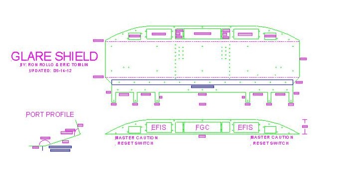
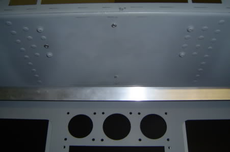
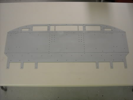
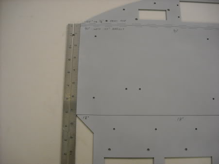
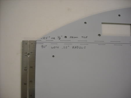
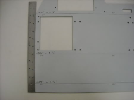
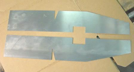
(Posted by Shane Barnes on 07-11-09) Quote from Ron "Strong enough that if someone where to reach out and steady themselves while getting in or out, it won't budge!" Great design Ron, I steady myself all the time using the glare shield while getting in and out of the generic enclosed sim that I have now, I'd say I will be doing the same thing when 007 is completed. (Posted by Rick Trantham on 07-08-09) This is probably a question for Tom, but I'll ask here anyway. I know the aluminum you're using is 1/16" thick, but what type of aluminum is being used? There are many kinds. (Posted by Ron Rollo on 07-09-09) I'm not sure what type it is but I don't think it was meant for bending. But with that said....... IT BENDS PERFECTLY WITHOUT CRACKING OR COMPROMISING THE STRENGTH OF THE PART! I could not be happier with the quality of the aluminum that Tom is using. It will suite us just fine. By the way, again, for those of you who are thinking about getting a set from Tom, I am working on an update to the Glare Shield. It will have an additional 65 holes in it that you won't have to drill manually. About half of the new holes are for dummies screws, but the other half are for the Glare shield supports and the Light bracket, or "Lamp shade" as we call it. After you put all the 5/32" rivets and screws in your new glare shield, you will think you have the real thing! In case any of you missed it, you have to take these parts to a metal shop to have them bent in a heavy duty break. There is no way around this. Don't think for a second that you can do this on your own in the back garage. I spent $50.00 to have all the bends put in my set. Call this PAR and see if you can get it done for about the same or a little less. I found $50.00 to be more than far especially because they did it perfectly! By the way, I have many projects and one of them that is a priority is finishing up the drawings of the big items in the shell, getting them converted over to PDF's and posted on the hangar for guys like you. I hope to have this completed by next Tuesday, (with Eric's help!) (Posted by Eric Tomlin on 07-10-09) Just wanted to post up a quick drawing of the newly modified Glare Shield that Ron has created from his own work. Tom has been sent the file so this version should be available from here on out. It adds about 70 holes to the underside of the glareshield as well as some other mods that suit the monitor support design that Ron has created: (If you would like a .dxf CAD file of this drawing, you will find it at the bottom of this post.) Photo of some of the rivets and screws under the Glare Shield. Notice that one of the Rivets has not been filled in yet: (Posted by Dean S. on 09-11-09) Hey Guys! Mail came today....Many thanks to Tom Goldberg for getting the MIP to me! Now for some questions. They look different than the other pics of MIPS in this post. On the MIP the DU 1,2,3,4 don't have the longer hole/slots like in the other MIPS. On the Glare Shield the bottom is different as it has tanges?... Lastly, In order to get this bent in the right places I looked at the PDF "miplowerpanelangleprofile" and I'm at a loss as to how to transfer over lines to mark for the machine shop person. Anyone have a straight on view with lines drawn across them I can look at? Other than that these look great! Can't wait to get this going! UPDATE: MIP Sanded and waiting for Ron's photos: (Posted by Ron Rollo on 09-12-09) The Glare shield has two bends in it. The one under the FGC and the EFIS is a 90 degree bend with a .25" radius in it. The other bend in the Glare Shield further back is 18 degrees and as sharp as the brake will make it which usually works out to about .0625" radius. The fingers on the Glare Shield at the back of it will be bent by you later on when your MIP Backer is complete. The MIP has three bends in it. All of them are as sharp as the brake can make it. The bend between the MIP and the lower panels is 10 degrees. The bend under the lower panels is 90 degrees. The last bend under the lower panels is 30 degrees. I call this the "shin protector bend". Without it, you could loose some skin on the front part of your leg if your not careful getting in and out of the sim. Dean, I know you can't wait to run out and bend your aluminum, but I have to tell you that this is one of the most critical parts of the whole sim build. If you don't get it right your gonna be ordering a second set from Tom! With that said, and as a matter of fact, I am prepping Shane's aluminum today. To prep it for bending, I sand all the parts down with an orbital sander on both sides to remove any of the big scratches in it. (It is easier to do it now when everything is still flat.) Then I prime just the front sides of the parts. Be mindful of which side is the front on all of the parts because there is a difference! Then I mark where the bend lines will go and even write the bend angles next to the line so that the guy bending has a less chance of screwing it up. I will have pictures of this by tonight for you and the exact measurements of where you need to place your lines. This should make bending the aluminum easy and you along with future builders will feel confident about doing it! The Glare Shield: An overview of the Glare Shield with the bend lines drawn on it: This is a photo with a scale ruler in it. The 18 degree bend line at the bottom left is right at the point where the 45 degree angle starts: The center of the 90 degree bend line at the top left of the photo is .125" or 1/8th" from the corner point. Notice that I have also drawn in the beginning and end points where this .25" or 1/4th" radius is. As a matter of fact, the top radius line IS lined up with the corner points. This is the only bend that ask for a little extra attention! And here is the MIP with the lower panels: Having 1/8th" backer panels makes it easy to figure out where the 10 degree and 90 degree bends are. I placed the lower panels on the aluminum MIP and drew the lines accordingly. This insures that we will not have issues later on: Measuring from the bottom up, the 30 degree bend is 1.1875" or 1 3/16th" high. The 90 degree bend is 4.9375" or 4 15/16th" from the bottom. And the 10 degree bend is 10.25" or 10 1/4th" from the bottom. If you follow these measurements, angles and radius', you can't go wrong. Shane, these are your parts man! (Posted by Shane Barnes on 09-12-09) Look at Ron, just marking all over my parts, a man can't have nothing! Just kidding, really nice to see those marks on there. A year ago I never thought I would be at this point of a build. I was just getting started on the generic sim that I built. Eric, Ron, Scott, Dave, Vince, Rick, Tom and Jason, I really appreciate all the help you guys have given me over the past year! I was reading about the Testors paint and the cost associated with it. If you have access to an air compressor / paint gun you should be able to buy one can of the Testors paint, spray a test panel, then take that panel to an auto parts house that mixes paint. Most are equipped with computers that can match the paint color exact. Then get it mixed in a larger quantity such as a quart, some places will mix in pints. This might be a little cheaper. I would advise using a self etching primer as a base coat. I would also advise prepping the aluminum with a good sanding followed by washing the parts with Dawn dish washing liquid (the blue color). This will remove any oil or grease from the parts. I used an automotive grade primer as I had access to an air compressor and spray gun. M next choice would be a self etching primer that you can find in cans, that will work just as well. Once you get a couple coats of self etching primer on I would lightly sand again avoiding sanding thru to the aluminum to get the parts prepped for your top coat. (Posted by Eric Tomlin on 09-13-09) The right color (confirmed via a Honeywell doc that a friend had one time) is the FS36118. Testors has this as a Model Master series, gunship gray FS36118. It's expensive at $5 give or take a can and you need about 12-15 for the whole aircraft IF you paint your backer panels too. Several of us are painting our backer panels because it will be quite a while before we get the front panels made available. After your metal is bent and you have all the other stuff ready I'd recommend any good quality gray paint/primer until you can purchase this Testors spray can 36118. (Posted by Ron Rollo on 09-13-09) I prime the front of the aluminum for a couple reason. One, so the guys at the metal shop know what side is the front. Second, it is the first coat and attempt to fill in any little scratches that the sanders left behind. One or two cans of 99 cent primer from Wal Mart will do. I have painted four sets of the aluminum parts with no issues. I use an orbital sander first while everything is still flat, then I paint it with 99 cent primer. Then I mark the bend lines. And then the bending process. Later on after you fit 99% of all your panels and components onto the MIP, then you can paint it with Gunship Gray or whatever you prefer. If your dealing with a metal shop that has a 48 inch break, they should have someone who knows how to use it. Although it is nerve racking when you drop off the aluminum, hoping it turns out okay after a day or two. Later after the bending and mishandling of your precious parts by the union workers, you will re sand and paint them with the Gunship gray. (Posted by Tom Goldberg on 03-04-10) Now that I finally have some time to work on my own sim I thought I would get my MIP and glareshield cut and bent. Now that it is done we decided to make the glare shield bracket but after looking around my small town, I couldn't find any aluminum L channel anywhere so I decided to make it myself on the waterjet. Turns out it was a good idea and less work than cutting with tin snips. Anyway I thought I would add this as an optional piece that can be added to the MIP,TQ,glareshield kit if anyone needs them. If you have your own break you can buy the parts just cut flat which you simply bend the piece at the half way mark length wise to 90 degrees and fold the V cut so it touches until you have a perfect 18 degree bend ready for the glareshield: (Posted by Mark Speechley on 11-07-11) There is no mention of the light bracket in relation to the Glare shield. Tell me if this is right. 1/16" aluminum left untouched for shine. 2" X 35.75". Bent at 1" 90 deg. (Posted by Ron Rollo on 11-07-11) Hey Mark, take a look at the PDF that shows exactly where the "light shade" goes. Only thing wrong on it is the length measurement. You are correct at 35.75" long. Use "L" angle, 1"X1" aluminum. You can find it at hardware stores. Also, there is nothing shiny in the flight deck of the Lear. (Well, there are a few things) They try to paint everything flat so that the sun does not reflect light causing more points of lights than there needs to be. In other words, in a perfect flight deck environment, the only points of light would be that of the indicator lights, instruments and gauges. So in this case of the Glareshield light bracket, it is painted Gunship Gray, or what ever your main color for your MIP is. If you were referring to my pictures above, I had the MIP and Glareshield painted in primer. The Light bracket was not painted yet. (Posted by Eric Tomlin on 11-07-11) Model Master Gunship Gray/Grey is the color used on our panels and other parts, which is supposedly FS (Federal Standard) 36118. However, compared to real LJ45 panels I've got on hand, the color we use is a slight bit bluer than the real. It's very close though. I'm not sure if you can get this paint on Oz. Everything you receive from me will be painted this color. Krylon primer gray is a very close 2nd to the Model Master, but as you can imagine does not dry as hard and would have to be coated with a clear enamel to protect from wear. (Posted by Alan Norris on 11-18-11) I have my light shield fitted and have quite a few holes that I don't see any use for. For instance there are extra holes parallel to the brackets, two down the middle and 6 across the back edge (are these for attaching MIP lighting)?. I know that maybe a couple are for the cockpit voice recorder mic. I know you said that some were for holding up the glare shield (which we don't do) and you also said that you filled in some with JB Weld and sand them down to look like the real thing. If they are sanded down then you won't see them. I'm not sure on what to do with these extras, fill them in with screws? (Posted by Shane Barnes on 11-18-11) Some of these screws may be used to hold the glare shield (vinyl) down as well as holding the FGC in place, depending on who makes/how it's made. And then some of the holes, about 10 of them will be open, in other words a hole with no screws. This is how they are in the real 45. As for filling with JB weld and sanding, I think what you are talking about is how Ron and I did the rivets. The rivet heads on the underside of the glareshield are filled with a small amount of JB weld then sanded to make them appear to be a "round head" rivet vs. a pop rivet. Here is a photo of the underside of a real Lear glareshield. Note the open holes and the filled rivet heads. You can see six of the open holes in the photo, four more holes are in the same areas on the other end of the shield that is out of view in the photo: (Posted by Shane Barnes on 07-11-09) Quote from Ron "Strong enough that if someone where to reach out and steady themselves while getting in or out, it won't budge!" Great design Ron, I steady myself all the time using the glare shield while getting in and out of the generic enclosed sim that I have now, I'd say I will be doing the same thing when 007 is completed. (Posted by Rick Trantham on 07-08-09) This is probably a question for Tom, but I'll ask here anyway. I know the aluminum you're using is 1/16" thick, but what type of aluminum is being used? There are many kinds. (Posted by Ron Rollo on 07-09-09) I'm not sure what type it is but I don't think it was meant for bending. But with that said....... IT BENDS PERFECTLY WITHOUT CRACKING OR COMPROMISING THE STRENGTH OF THE PART! I could not be happier with the quality of the aluminum that Tom is using. It will suite us just fine. By the way, again, for those of you who are thinking about getting a set from Tom, I am working on an update to the Glare Shield. It will have an additional 65 holes in it that you won't have to drill manually. About half of the new holes are for dummies screws, but the other half are for the Glare shield supports and the Light bracket, or "Lamp shade" as we call it. After you put all the 5/32" rivets and screws in your new glare shield, you will think you have the real thing! In case any of you missed it, you have to take these parts to a metal shop to have them bent in a heavy duty break. There is no way around this. Don't think for a second that you can do this on your own in the back garage. I spent $50.00 to have all the bends put in my set. Call this PAR and see if you can get it done for about the same or a little less. I found $50.00 to be more than far especially because they did it perfectly! By the way, I have many projects and one of them that is a priority is finishing up the drawings of the big items in the shell, getting them converted over to PDF's and posted on the hangar for guys like you. I hope to have this completed by next Tuesday, (with Eric's help!) (Posted by Eric Tomlin on 07-10-09) Just wanted to post up a quick drawing of the newly modified Glare Shield that Ron has created from his own work. Tom has been sent the file so this version should be available from here on out. It adds about 70 holes to the underside of the glareshield as well as some other mods that suit the monitor support design that Ron has created: (If you would like a .dxf CAD file of this drawing, you will find it at the bottom of this post.) Photo of some of the rivets and screws under the Glare Shield. Notice that one of the Rivets has not been filled in yet: (Posted by Dean S. on 09-11-09) Hey Guys! Mail came today....Many thanks to Tom Goldberg for getting the MIP to me! Now for some questions. They look different than the other pics of MIPS in this post. On the MIP the DU 1,2,3,4 don't have the longer hole/slots like in the other MIPS. On the Glare Shield the bottom is different as it has tanges?... Lastly, In order to get this bent in the right places I looked at the PDF "miplowerpanelangleprofile" and I'm at a loss as to how to transfer over lines to mark for the machine shop person. Anyone have a straight on view with lines drawn across them I can look at? Other than that these look great! Can't wait to get this going! UPDATE: MIP Sanded and waiting for Ron's photos: (Posted by Ron Rollo on 09-12-09) The Glare shield has two bends in it. The one under the FGC and the EFIS is a 90 degree bend with a .25" radius in it. The other bend in the Glare Shield further back is 18 degrees and as sharp as the brake will make it which usually works out to about .0625" radius. The fingers on the Glare Shield at the back of it will be bent by you later on when your MIP Backer is complete. The MIP has three bends in it. All of them are as sharp as the brake can make it. The bend between the MIP and the lower panels is 10 degrees. The bend under the lower panels is 90 degrees. The last bend under the lower panels is 30 degrees. I call this the "shin protector bend". Without it, you could loose some skin on the front part of your leg if your not careful getting in and out of the sim. Dean, I know you can't wait to run out and bend your aluminum, but I have to tell you that this is one of the most critical parts of the whole sim build. If you don't get it right your gonna be ordering a second set from Tom! With that said, and as a matter of fact, I am prepping Shane's aluminum today. To prep it for bending, I sand all the parts down with an orbital sander on both sides to remove any of the big scratches in it. (It is easier to do it now when everything is still flat.) Then I prime just the front sides of the parts. Be mindful of which side is the front on all of the parts because there is a difference! Then I mark where the bend lines will go and even write the bend angles next to the line so that the guy bending has a less chance of screwing it up. I will have pictures of this by tonight for you and the exact measurements of where you need to place your lines. This should make bending the aluminum easy and you along with future builders will feel confident about doing it! The Glare Shield: An overview of the Glare Shield with the bend lines drawn on it: This is a photo with a scale ruler in it. The 18 degree bend line at the bottom left is right at the point where the 45 degree angle starts: The center of the 90 degree bend line at the top left of the photo is .125" or 1/8th" from the corner point. Notice that I have also drawn in the beginning and end points where this .25" or 1/4th" radius is. As a matter of fact, the top radius line IS lined up with the corner points. This is the only bend that ask for a little extra attention! And here is the MIP with the lower panels: Having 1/8th" backer panels makes it easy to figure out where the 10 degree and 90 degree bends are. I placed the lower panels on the aluminum MIP and drew the lines accordingly. This insures that we will not have issues later on: Measuring from the bottom up, the 30 degree bend is 1.1875" or 1 3/16th" high. The 90 degree bend is 4.9375" or 4 15/16th" from the bottom. And the 10 degree bend is 10.25" or 10 1/4th" from the bottom. If you follow these measurements, angles and radius', you can't go wrong. Shane, these are your parts man! (Posted by Shane Barnes on 09-12-09) Look at Ron, just marking all over my parts, a man can't have nothing! Just kidding, really nice to see those marks on there. A year ago I never thought I would be at this point of a build. I was just getting started on the generic sim that I built. Eric, Ron, Scott, Dave, Vince, Rick, Tom and Jason, I really appreciate all the help you guys have given me over the past year! I was reading about the Testors paint and the cost associated with it. If you have access to an air compressor / paint gun you should be able to buy one can of the Testors paint, spray a test panel, then take that panel to an auto parts house that mixes paint. Most are equipped with computers that can match the paint color exact. Then get it mixed in a larger quantity such as a quart, some places will mix in pints. This might be a little cheaper. I would advise using a self etching primer as a base coat. I would also advise prepping the aluminum with a good sanding followed by washing the parts with Dawn dish washing liquid (the blue color). This will remove any oil or grease from the parts. I used an automotive grade primer as I had access to an air compressor and spray gun. M next choice would be a self etching primer that you can find in cans, that will work just as well. Once you get a couple coats of self etching primer on I would lightly sand again avoiding sanding thru to the aluminum to get the parts prepped for your top coat. (Posted by Eric Tomlin on 09-13-09) The right color (confirmed via a Honeywell doc that a friend had one time) is the FS36118. Testors has this as a Model Master series, gunship gray FS36118. It's expensive at $5 give or take a can and you need about 12-15 for the whole aircraft IF you paint your backer panels too. Several of us are painting our backer panels because it will be quite a while before we get the front panels made available. After your metal is bent and you have all the other stuff ready I'd recommend any good quality gray paint/primer until you can purchase this Testors spray can 36118. (Posted by Ron Rollo on 09-13-09) I prime the front of the aluminum for a couple reason. One, so the guys at the metal shop know what side is the front. Second, it is the first coat and attempt to fill in any little scratches that the sanders left behind. One or two cans of 99 cent primer from Wal Mart will do. I have painted four sets of the aluminum parts with no issues. I use an orbital sander first while everything is still flat, then I paint it with 99 cent primer. Then I mark the bend lines. And then the bending process. Later on after you fit 99% of all your panels and components onto the MIP, then you can paint it with Gunship Gray or whatever you prefer. If your dealing with a metal shop that has a 48 inch break, they should have someone who knows how to use it. Although it is nerve racking when you drop off the aluminum, hoping it turns out okay after a day or two. Later after the bending and mishandling of your precious parts by the union workers, you will re sand and paint them with the Gunship gray. (Posted by Tom Goldberg on 03-04-10) Now that I finally have some time to work on my own sim I thought I would get my MIP and glareshield cut and bent. Now that it is done we decided to make the glare shield bracket but after looking around my small town, I couldn't find any aluminum L channel anywhere so I decided to make it myself on the waterjet. Turns out it was a good idea and less work than cutting with tin snips. Anyway I thought I would add this as an optional piece that can be added to the MIP,TQ,glareshield kit if anyone needs them. If you have your own break you can buy the parts just cut flat which you simply bend the piece at the half way mark length wise to 90 degrees and fold the V cut so it touches until you have a perfect 18 degree bend ready for the glareshield: (Posted by Mark Speechley on 11-07-11) There is no mention of the light bracket in relation to the Glare shield. Tell me if this is right. 1/16" aluminum left untouched for shine. 2" X 35.75". Bent at 1" 90 deg. (Posted by Ron Rollo on 11-07-11) Hey Mark, take a look at the PDF that shows exactly where the "light shade" goes. Only thing wrong on it is the length measurement. You are correct at 35.75" long. Use "L" angle, 1"X1" aluminum. You can find it at hardware stores. Also, there is nothing shiny in the flight deck of the Lear. (Well, there are a few things) They try to paint everything flat so that the sun does not reflect light causing more points of lights than there needs to be. In other words, in a perfect flight deck environment, the only points of light would be that of the indicator lights, instruments and gauges. So in this case of the Glareshield light bracket, it is painted Gunship Gray, or what ever your main color for your MIP is. If you were referring to my pictures above, I had the MIP and Glareshield painted in primer. The Light bracket was not painted yet. (Posted by Eric Tomlin on 11-07-11) Model Master Gunship Gray/Grey is the color used on our panels and other parts, which is supposedly FS (Federal Standard) 36118. However, compared to real LJ45 panels I've got on hand, the color we use is a slight bit bluer than the real. It's very close though. I'm not sure if you can get this paint on Oz. Everything you receive from me will be painted this color. Krylon primer gray is a very close 2nd to the Model Master, but as you can imagine does not dry as hard and would have to be coated with a clear enamel to protect from wear. (Posted by Alan Norris on 11-18-11) I have my light shield fitted and have quite a few holes that I don't see any use for. For instance there are extra holes parallel to the brackets, two down the middle and 6 across the back edge (are these for attaching MIP lighting)?. I know that maybe a couple are for the cockpit voice recorder mic. I know you said that some were for holding up the glare shield (which we don't do) and you also said that you filled in some with JB Weld and sand them down to look like the real thing. If they are sanded down then you won't see them. I'm not sure on what to do with these extras, fill them in with screws? (Posted by Shane Barnes on 11-18-11) Some of these screws may be used to hold the glare shield (vinyl) down as well as holding the FGC in place, depending on who makes/how it's made. And then some of the holes, about 10 of them will be open, in other words a hole with no screws. This is how they are in the real 45. As for filling with JB weld and sanding, I think what you are talking about is how Ron and I did the rivets. The rivet heads on the underside of the glareshield are filled with a small amount of JB weld then sanded to make them appear to be a "round head" rivet vs. a pop rivet. Here is a photo of the underside of a real Lear glareshield. Note the open holes and the filled rivet heads. You can see six of the open holes in the photo, four more holes are in the same areas on the other end of the shield that is out of view in the photo: Aluminum MIP and Glareshield Discussion
![]()
![]()
2017-10-10