


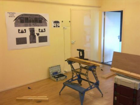
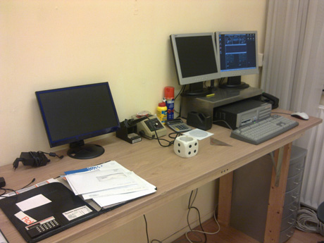
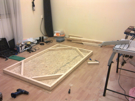
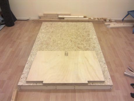
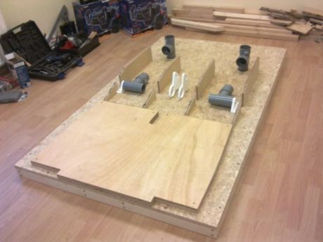
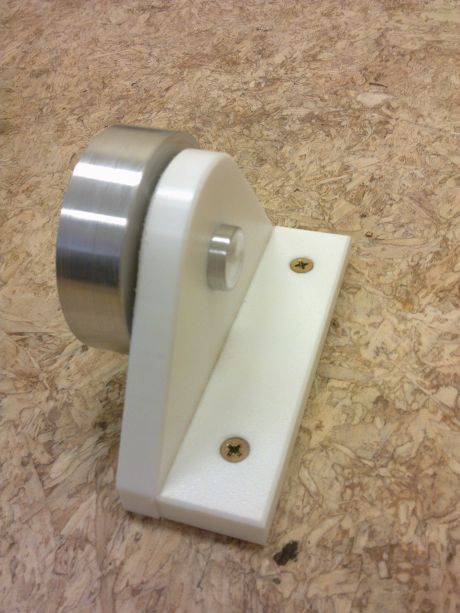
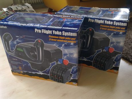
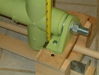
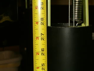
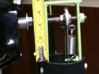
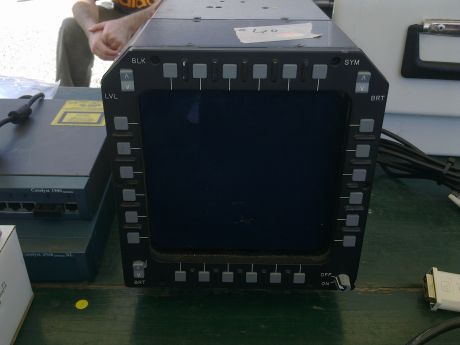
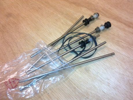
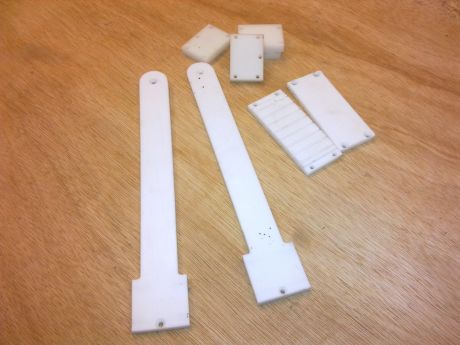
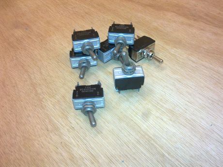
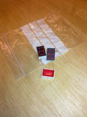
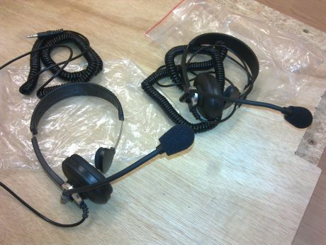
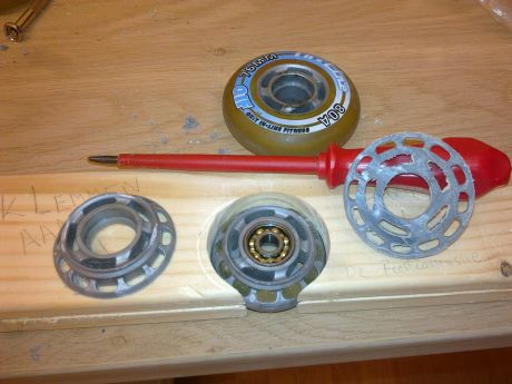
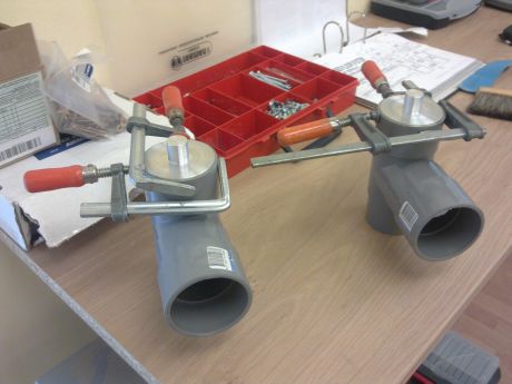
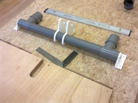
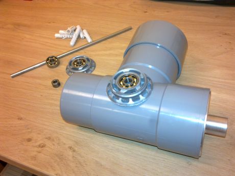
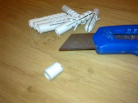
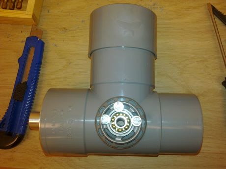
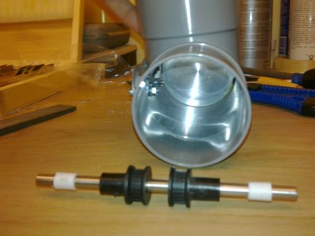
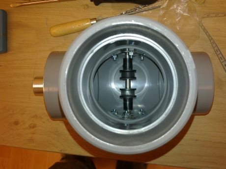
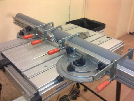
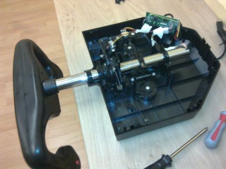
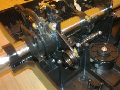
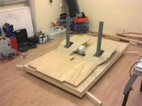
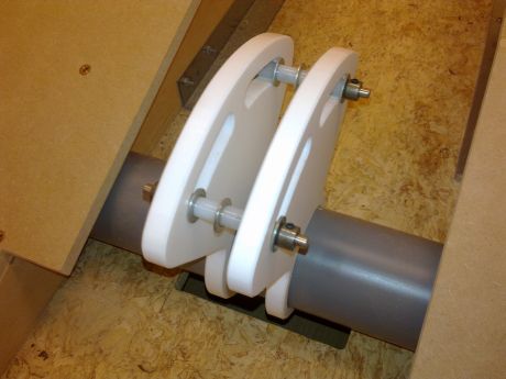
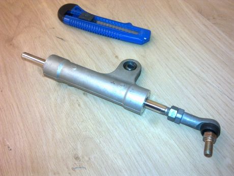
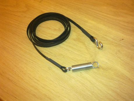
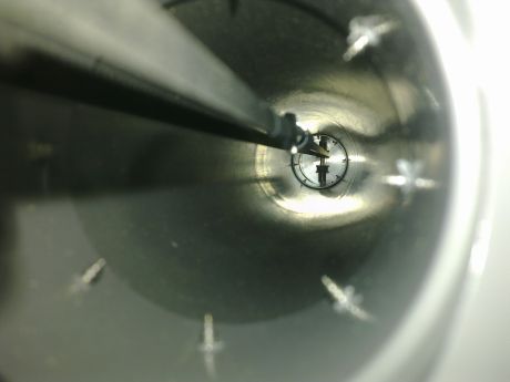
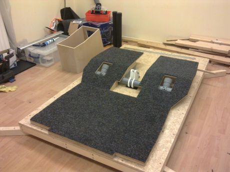
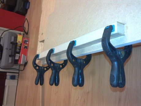
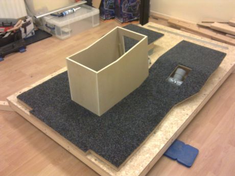
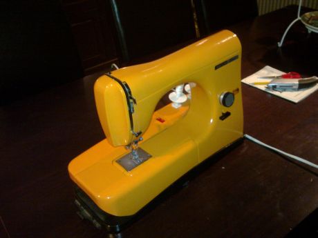
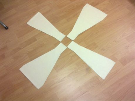
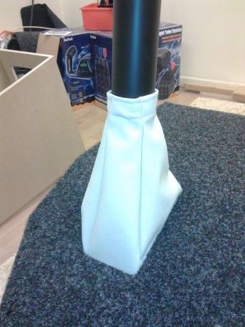
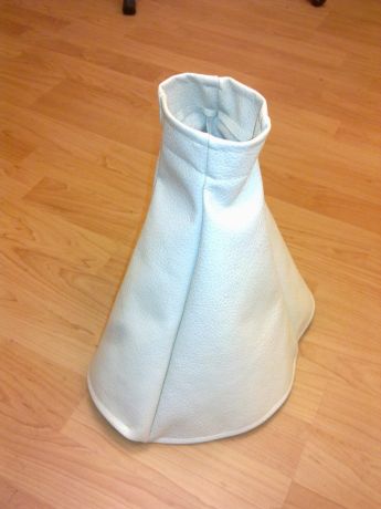
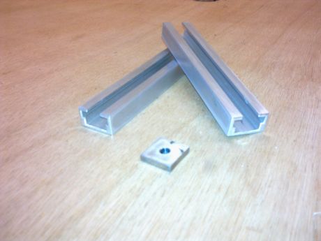
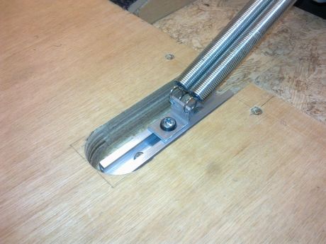
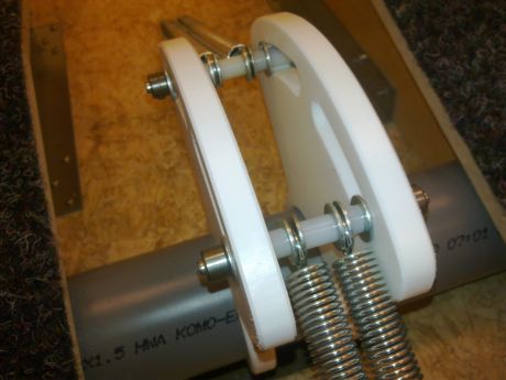
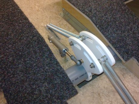
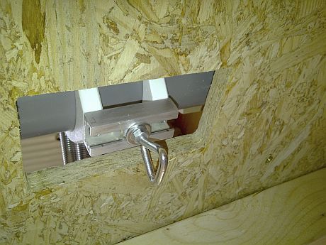
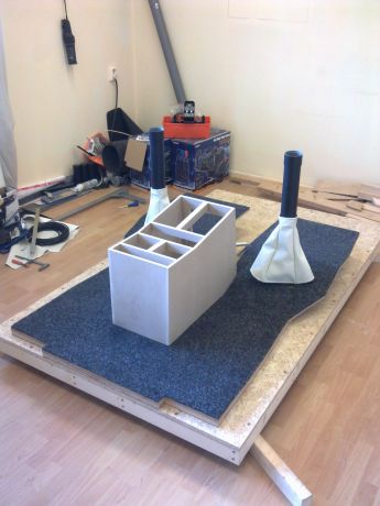
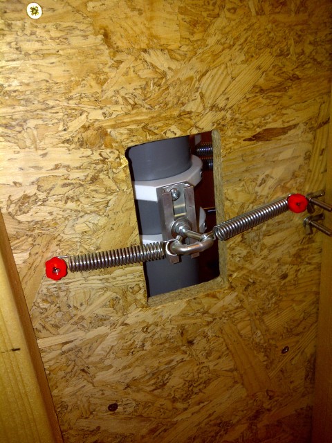
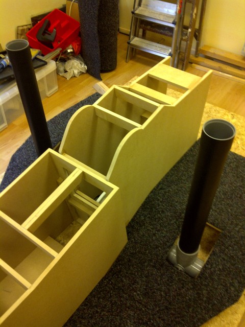
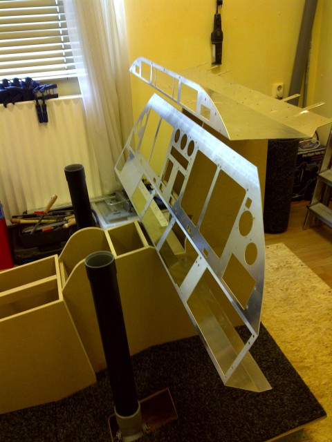
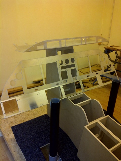
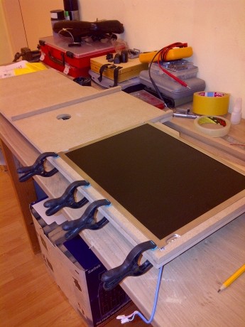
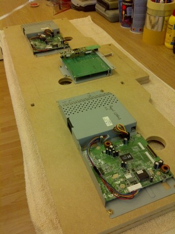
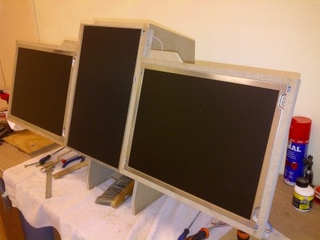
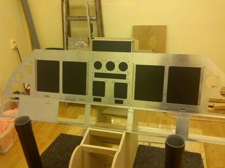
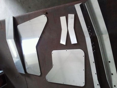
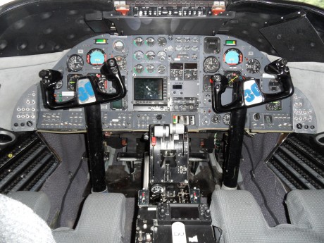
(Original thread started on 04-29-10 by Ronald Pater) I almost finished preparing my workshop for the build of my Lear45! I have a nice large room with great lightning and some serious FESTO tools coming up. I needed to build a proper workbench first, so I made some pics to give an impression of my workshop. I used some 'left-overs' for the frame: Top-class simplicity, but it's very sturdy and gives me enough work space (2,50 meter). Short term to-do-list: - Wait for the saw table and some other tools - Getting a computer with wireless internet connection and a printer - Start designing the base floor with the column controls! I got most of the tools I need for now (including a very nice saw table, thanks dad!). I've also managed to get all the LCD screens needed (2x standard 15" and 1x 15.4" wide) and a little computer with a wireless network adapter. All the computers are across my home so I've set up a wireless network access point that connects them all. While managing all these things I bought WideFS and FSUIPC and installed Dave Ault's software on the computer in my workshop. I've installed WideFS and FSUIPC on my FSX (server) computer (which is on the complete opposite of my home, but also in the wireless network) and did some testing. It turns out great! It runs very smooth and I have to say that Dave did an outstanding job on the gauges, RMU's and CWP! The next thing I know I was working on the base floor which is almost finished and I hope to get started on the raised floor system and column controls very soon! I have so much fun doing this! I really need to thank Ron for the lower column parts which arrived last week and all of his great advise and detailed information he e-mail me in the last two months. Thanks Ron! Here's a little impression: The hot weather in the past 5 weeks kept me from working hard on the project, in-home temperatures raised to 33°C! But... UPDATE: I've worked a bit on the raised floor. I glued two 18mm multiplex plates together and shaped them as in the Raised floor PDF from Ron Rollo: Here I tried to make some support for the raised floor, but It needed some adjusting because the 'mouse hole' for the control columns is too high and weakened the structure: As you may have noticed, I used Ron Rollo's plastic column control parts in the opposite direction. That's because I couldn't find PVC tubes smaller than 70mm (1.78") and it didn't fit any other way. I'm using 70mm for the horizontal column parts, and 80mm for the vertical: (Original thread started on 04-29-10 by Ronald Pater) I almost finished preparing my workshop for the build of my Lear45! I have a nice large room with great lightning and some serious FESTO tools coming up. I needed to build a proper workbench first, so I made some pics to give an impression of my workshop. I used some 'left-overs' for the frame: Top-class simplicity, but it's very sturdy and gives me enough work space (2,50 meter). Short term to-do-list: - Wait for the saw table and some other tools - Getting a computer with wireless internet connection and a printer - Start designing the base floor with the column controls! I got most of the tools I need for now (including a very nice saw table, thanks dad!). I've also managed to get all the LCD screens needed (2x standard 15" and 1x 15.4" wide) and a little computer with a wireless network adapter. All the computers are across my home so I've set up a wireless network access point that connects them all. While managing all these things I bought WideFS and FSUIPC and installed Dave Ault's software on the computer in my workshop. I've installed WideFS and FSUIPC on my FSX (server) computer (which is on the complete opposite of my home, but also in the wireless network) and did some testing. It turns out great! It runs very smooth and I have to say that Dave did an outstanding job on the gauges, RMU's and CWP! The next thing I know I was working on the base floor which is almost finished and I hope to get started on the raised floor system and column controls very soon! I have so much fun doing this! I really need to thank Ron for the lower column parts which arrived last week and all of his great advise and detailed information he e-mail me in the last two months. Thanks Ron! Here's a little impression: The hot weather in the past 5 weeks kept me from working hard on the project, in-home temperatures raised to 33°C! But... UPDATE: I've worked a bit on the raised floor. I glued two 18mm multiplex plates together and shaped them as in the Raised floor PDF from Ron Rollo: Here I tried to make some support for the raised floor, but It needed some adjusting because the 'mouse hole' for the control columns is too high and weakened the structure: As you may have noticed, I used Ron Rollo's plastic column control parts in the opposite direction. That's because I couldn't find PVC tubes smaller than 70mm (1.78") and it didn't fit any other way. I'm using 70mm for the horizontal column parts, and 80mm for the vertical: I'm not using a ball bearing set-up for the column controls. I'm in contact with a guy at a local machine factory and he made these very nice aluminum plugs for me. With a little grease and a maybe a spring this works great! The galvanized screws are going to be replaced by strong bolts when I know the exact position of the parts: Big news! I've had contact with Saitek in Germany and told my story about building the sim. I've asked for spare part yokes that I could use on the control columns. The nice guy who helped me found two complete yoke sets in great condition (only some small malfunction on the TQ) and sent me those two sets completely free! Amazing isn't it? +10 for Saitek! REQUEST: Does anyone know the exact (horizontal) position of the two control columns. On some reference pictures it looks like the steering column is slightly off to the outer side, and not in the center of the column gaps in the raised floor. I hope you guys know what I mean. Does anyone know the height of the steering columns? I can't find that kind of information anywhere and I don't like to guess on this one. (Posted by Ron Rollo on 04-08-10) Great looking raised floor section you have there. Sometime you have to think outside of the box or a bit off the beaten path to make things work. Scott Wegner took a field trip into a Lear45 about 8 months ago. Here is the information that he collected that you are looking for: Distance from the center of one control column head to the center of the other control column head is 28 9/16". 22 1/2" from the ramped floor to the bottom of the column head or 27 5/8" from the ramped floor to the top of the column head. This is the raw data that you are looking for. You may find that you will need to tweak it a tad to make it fit or work for you. As an example, my "on center" column spacing from left to right is 28 inches even, a tad shorter than what Scott says it is. I found that 28 inches would work best when you take everything into consideration with the shell, pedals, seats and rudder pedal cover boxes. This idea is that you want everything to line up! (Posted by Shane Barnes on 08-04-10) I was able to get you a couple of photos showing the height of my columns. This photo is giving you a reference point that I measured from since you are using parts from Ron you will be able to recognize the end support. My columns are temporarily mounted to a jig to hold them while I have them removed from the shell: This photo is showing the measurement from the bottom of the end support (picture above) to the top of the PVC column which is 27.750 inches: The photo below shows a measurement from the top of the PVC column to the top of the metal framework that holds the yokes and crossover cables. Note that the measurement is about 4.5 inches WHICH IS TOO TALL. The top of the framework sticks up higher than the middle of the yoke which I don't want. If you look at the real L45 yoke/column you will notice that the top of the column cover is level with the center of the 45 yoke so keep that in mind when you start to attach your yokes. As you can see I will need to modify the top of my framework to make it work with the yokes. I really like the looks of your raised floor. I like the revisions that you have made to your column setup as well. Sometimes we find it necessary to go a different route, especially when parts are not available locally: (Posted by Ronald Pater on 09-30-10) The last two months I wasn't very active working on my project but that has a few reasons. There's a lot happening in my private life; I lost my job as studio equipment sales specialist at a local music instrument store in July, found a new job at huge IT company, my girlfriend is moving in with me and so on. In the mean time I tried to develop the lower control column parts and made some sketches with a friend who has some more experience in mechanical stuff than I have. I've had some difficulties with the mechanical parts and sometimes I get caught up in the detail as the perfectionist I am... But my friend gave me some wise words: "Stop thinking, start building!" And of course he's completely right, as usual by the way. Last Saturday we went to a so called "Radio market" in the local area. This event takes place once a year and I've never been there before. I always thought it was a small scale radio-electronic related event (mainly for ham amateur radio fanatics/pirates, we have a lot of them in the Netherlands)..... I was wrong. The event was HUGE and I found a lot of stuff that could help me building my sim! Radio Market shot 2, huge terrain as you can see! I was stunned when I saw this authentic FA-18 MFD display which actually came from a real simulator! The price was a shocking € 40,- but when I asked some questions, the guy revealed that this MFD was broken. If anyone is interested, I've got the guys phone number. Amazing, isn't it? We walked the radio market for about 4 or 5 hours over and over, looking for parts and other useful stuff. This is where I came home with: I've got 3 of these bags with axes, pulleys, (set)rings and more for just € 1,- per bag! Could come in very handy for building the mechanical parts of the column controls. These parts came from old reading devices designed for poorly sighted people. Some Teflon parts. Very nice material to work with, i.e. for designing the manual gear lever or other small mechanical parts: A lot of very nice, large and heavy switches for € 1,- each. Some were used, other were brand new. They have approximately the same size as the Honeywell toggle switches so these can be used as dummy's! Three great numeric LED displays for just € 4,50! I'm gonna use this catch for the APU display. (Still need to figure out if the APU amp data can be interfaced, if not the LED's will display a fixed number when the APU is switched on): Last but not least: two very nice retro looking headsets. The guy who sold them told me they were good quality headsets (Maxon), produced a long time ago but brand new! Just € 7,50 each. I think they will do great in the sim! When I came home from this great experience I had a lot of new energy and started to redesign the mechanical parts inside the column controls. I now had the axes, pulleys and more to work with! I still needed some ball bearing parts to fixate the axes. I'm not using a ball bearing set-up for the column controls. I'm in contact with a guy at a local machine factory and he made these very nice aluminum plugs for me. With a little grease and a maybe a spring this works great! The galvanized screws are going to be replaced by strong bolts when I know the exact position of the parts: Big news! I've had contact with Saitek in Germany and told my story about building the sim. I've asked for spare part yokes that I could use on the control columns. The nice guy who helped me found two complete yoke sets in great condition (only some small malfunction on the TQ) and sent me those two sets completely free! Amazing isn't it? +10 for Saitek! REQUEST: Does anyone know the exact (horizontal) position of the two control columns. On some reference pictures it looks like the steering column is slightly off to the outer side, and not in the center of the column gaps in the raised floor. I hope you guys know what I mean. Does anyone know the height of the steering columns? I can't find that kind of information anywhere and I don't like to guess on this one. (Posted by Ron Rollo on 04-08-10) Great looking raised floor section you have there. Sometime you have to think outside of the box or a bit off the beaten path to make things work. Scott Wegner took a field trip into a Lear45 about 8 months ago. Here is the information that he collected that you are looking for: Distance from the center of one control column head to the center of the other control column head is 28 9/16". 22 1/2" from the ramped floor to the bottom of the column head or 27 5/8" from the ramped floor to the top of the column head. This is the raw data that you are looking for. You may find that you will need to tweak it a tad to make it fit or work for you. As an example, my "on center" column spacing from left to right is 28 inches even, a tad shorter than what Scott says it is. I found that 28 inches would work best when you take everything into consideration with the shell, pedals, seats and rudder pedal cover boxes. This idea is that you want everything to line up! (Posted by Shane Barnes on 08-04-10) I was able to get you a couple of photos showing the height of my columns. This photo is giving you a reference point that I measured from since you are using parts from Ron you will be able to recognize the end support. My columns are temporarily mounted to a jig to hold them while I have them removed from the shell: This photo is showing the measurement from the bottom of the end support (picture above) to the top of the PVC column which is 27.750 inches: The photo below shows a measurement from the top of the PVC column to the top of the metal framework that holds the yokes and crossover cables. Note that the measurement is about 4.5 inches WHICH IS TOO TALL. The top of the framework sticks up higher than the middle of the yoke which I don't want. If you look at the real L45 yoke/column you will notice that the top of the column cover is level with the center of the 45 yoke so keep that in mind when you start to attach your yokes. As you can see I will need to modify the top of my framework to make it work with the yokes. I really like the looks of your raised floor. I like the revisions that you have made to your column setup as well. Sometimes we find it necessary to go a different route, especially when parts are not available locally: (Posted by Ronald Pater on 09-30-10) The last two months I wasn't very active working on my project but that has a few reasons. There's a lot happening in my private life; I lost my job as studio equipment sales specialist at a local music instrument store in July, found a new job at huge IT company, my girlfriend is moving in with me and so on. In the mean time I tried to develop the lower control column parts and made some sketches with a friend who has some more experience in mechanical stuff than I have. I've had some difficulties with the mechanical parts and sometimes I get caught up in the detail as the perfectionist I am... But my friend gave me some wise words: "Stop thinking, start building!" And of course he's completely right, as usual by the way. Last Saturday we went to a so called "Radio market" in the local area. This event takes place once a year and I've never been there before. I always thought it was a small scale radio-electronic related event (mainly for ham amateur radio fanatics/pirates, we have a lot of them in the Netherlands)..... I was wrong. The event was HUGE and I found a lot of stuff that could help me building my sim! Radio Market shot 2, huge terrain as you can see! I was stunned when I saw this authentic FA-18 MFD display which actually came from a real simulator! The price was a shocking € 40,- but when I asked some questions, the guy revealed that this MFD was broken. If anyone is interested, I've got the guys phone number. Amazing, isn't it? We walked the radio market for about 4 or 5 hours over and over, looking for parts and other useful stuff. This is where I came home with: I've got 3 of these bags with axes, pulleys, (set)rings and more for just € 1,- per bag! Could come in very handy for building the mechanical parts of the column controls. These parts came from old reading devices designed for poorly sighted people. Some Teflon parts. Very nice material to work with, i.e. for designing the manual gear lever or other small mechanical parts: A lot of very nice, large and heavy switches for € 1,- each. Some were used, other were brand new. They have approximately the same size as the Honeywell toggle switches so these can be used as dummy's! Three great numeric LED displays for just € 4,50! I'm gonna use this catch for the APU display. (Still need to figure out if the APU amp data can be interfaced, if not the LED's will display a fixed number when the APU is switched on): Last but not least: two very nice retro looking headsets. The guy who sold them told me they were good quality headsets (Maxon), produced a long time ago but brand new! Just € 7,50 each. I think they will do great in the sim! When I came home from this great experience I had a lot of new energy and started to redesign the mechanical parts inside the column controls. I now had the axes, pulleys and more to work with! I still needed some ball bearing parts to fixate the axes. Yet again my friend came up with a great idea: he just bought some second hand inline skates for just € 4,50 at a local second hand shop. He disassembled them and that gave us 16 ball bearings of quite good quality! He didn't need them all for is own project, so I could get 4 of them. I already was searching online for some appropriate bearing houses (expensive stuff!) when we realized that the skate wheels actually were bearing houses themselves. They just needed some adjustment. Skate wheels disassembled and cut in half! A few weeks ago I already glued the alu plugs into the PVC parts: Basic set-up of the lower control column parts: Looking very good! The inside bore diameter of the ball bearings is 8mm, the axes I got are 6mm so we need a bearing bus to hold the axes. Searching online and at some local stores didn't result in anything. "Stop searching, start thinking creative!" (Thanks Peter!) These plugs were exactly 8mm on the outside and 6mm on the inside! The halved inline skate bearing houses mounted in to place with three M4 bolts: The neatly prepared axes with pulleys and busses, looking awesome! An inside look with the axes mounted in to place. Both sides now have the bearing housed mounted: Yet again my friend came up with a great idea: he just bought some second hand inline skates for just € 4,50 at a local second hand shop. He disassembled them and that gave us 16 ball bearings of quite good quality! He didn't need them all for is own project, so I could get 4 of them. I already was searching online for some appropriate bearing houses (expensive stuff!) when we realized that the skate wheels actually were bearing houses themselves. They just needed some adjustment. Skate wheels disassembled and cut in half! A few weeks ago I already glued the alu plugs into the PVC parts: Basic set-up of the lower control column parts: Looking very good! The inside bore diameter of the ball bearings is 8mm, the axes I got are 6mm so we need a bearing bus to hold the axes. Searching online and at some local stores didn't result in anything. "Stop searching, start thinking creative!" (Thanks Peter!) These plugs were exactly 8mm on the outside and 6mm on the inside! The halved inline skate bearing houses mounted in to place with three M4 bolts: The neatly prepared axes with pulleys and busses, looking awesome! An inside look with the axes mounted in to place. Both sides now have the bearing housed mounted: CONTINUATION: Overview of the complete assembled part, notice the (set)ring mounted on the end of the axis: When you finish the first part in a few hours, the next part is ready in no-time! Total overview of the lower control column parts. Al the radial movements are extremely smooth! I'm really happy with the results! The next parts I need to get are the right length of timing belts, but I'm on that right now. Also I soon will disassemble the Saitek Yokes to take a good look inside so I can get an idea of how to design the upper parts of the control columns. But before I can continue building, I will have to go on two weeks of training for my new job. Because this is quite far away from home, the company offered a hotel to stay. I guess my hands will be a bit itchy when I've got nothing to do all those evenings... However, the new job pays a lot better than my previous one, meaning I can invest more in the project! So in the end it's for a good cause. (Posted by Ron Rollo on 09-30-10) Your columns are looking great! As they say, "There's more than one way to skin a cat! And your friend is also right, sometime you just have to start building something. But obviously, you have to at least have a game plan in mind. As an example of "just start building something", I was not and still not sure exactly how I am going to work the roll axis part of the control columns. But I had enough of the column design figured out in my head to start building something. And I had to because at that time, I really was not even wanting to work on the columns. The task at that time was the raised floor but I had to have the column system in place so that I could work it into the design of the floors. Another little secret is, for me anyway, when I post some pictures of my latest work, it is not always what I had in mind when I started the job. It evolves as you move forward. Sometimes I have to do something twice if not three times before I am happy with the results. You guys only see the end result. This is one of the great things about sharing ideas. I would have never of thought to cut a skate wheel in half. But now that I have seen it, I will file it away in my head and you never know where that solution will find a home in the future. I am happy to hear that things are going well for you with the job and your girlfriend. Just be up front with her about your plans to build a full scale flight simulator. That way in the future, she can't complain to much! (Posted by Ronald Pater on 12-19-10) As the most of you already know, I found a nice new job in IT (Getronics Consulting) and things are working out just fine. I started in October with two weeks of training and I needed some time to settle down. Since my personal things are "stabilized" I couldn't wait continuing building the sim! I've been working on the raised floor section and the control columns. I don't have a CNC like most of you to cut out the floor parts in a very accurate way, but with a steady hand and some good tools I did quite well I guess. Also, I've been searching forever to find the right type of timing belts for the steering system. Of course, and as usual, no company in the Netherlands nor Europe could get me those belts (no stock or only business-to-business!). Finally I found a company in NY (econobelt.com) that could deliver up to 150 inches of MXL018 in one piece. I've ordered 5 pieces, just to be sure I would never have to search for those belts again. Some results: I added some strength to the raised floor parts. I needed to be sure that it could hold some weight and I want the sim to be foolproof of course. Cutting the control columns to right size: Here is where opened up the Saitek Yokes to take a good look inside. As you can see, the product is quite well build. Inside I found a really small interface with build-in USB hub, two pots and a neat piece of mechanical engineering: Saitek only used one V-shaped spring to center the Yoke with: The almost finished raised floor section. I did not cut the holes for the rudder pedals yet: CONTINUATION: Overview of the complete assembled part, notice the (set)ring mounted on the end of the axis: When you finish the first part in a few hours, the next part is ready in no-time! Total overview of the lower control column parts. Al the radial movements are extremely smooth! I'm really happy with the results! The next parts I need to get are the right length of timing belts, but I'm on that right now. Also I soon will disassemble the Saitek Yokes to take a good look inside so I can get an idea of how to design the upper parts of the control columns. But before I can continue building, I will have to go on two weeks of training for my new job. Because this is quite far away from home, the company offered a hotel to stay. I guess my hands will be a bit itchy when I've got nothing to do all those evenings... However, the new job pays a lot better than my previous one, meaning I can invest more in the project! So in the end it's for a good cause. (Posted by Ron Rollo on 09-30-10) Your columns are looking great! As they say, "There's more than one way to skin a cat! And your friend is also right, sometime you just have to start building something. But obviously, you have to at least have a game plan in mind. As an example of "just start building something", I was not and still not sure exactly how I am going to work the roll axis part of the control columns. But I had enough of the column design figured out in my head to start building something. And I had to because at that time, I really was not even wanting to work on the columns. The task at that time was the raised floor but I had to have the column system in place so that I could work it into the design of the floors. Another little secret is, for me anyway, when I post some pictures of my latest work, it is not always what I had in mind when I started the job. It evolves as you move forward. Sometimes I have to do something twice if not three times before I am happy with the results. You guys only see the end result. This is one of the great things about sharing ideas. I would have never of thought to cut a skate wheel in half. But now that I have seen it, I will file it away in my head and you never know where that solution will find a home in the future. I am happy to hear that things are going well for you with the job and your girlfriend. Just be up front with her about your plans to build a full scale flight simulator. That way in the future, she can't complain to much! (Posted by Ronald Pater on 12-19-10) As the most of you already know, I found a nice new job in IT (Getronics Consulting) and things are working out just fine. I started in October with two weeks of training and I needed some time to settle down. Since my personal things are "stabilized" I couldn't wait continuing building the sim! I've been working on the raised floor section and the control columns. I don't have a CNC like most of you to cut out the floor parts in a very accurate way, but with a steady hand and some good tools I did quite well I guess. Also, I've been searching forever to find the right type of timing belts for the steering system. Of course, and as usual, no company in the Netherlands nor Europe could get me those belts (no stock or only business-to-business!). Finally I found a company in NY (econobelt.com) that could deliver up to 150 inches of MXL018 in one piece. I've ordered 5 pieces, just to be sure I would never have to search for those belts again. Some results: I added some strength to the raised floor parts. I needed to be sure that it could hold some weight and I want the sim to be foolproof of course. Cutting the control columns to right size: Here is where opened up the Saitek Yokes to take a good look inside. As you can see, the product is quite well build. Inside I found a really small interface with build-in USB hub, two pots and a neat piece of mechanical engineering: Saitek only used one V-shaped spring to center the Yoke with: The almost finished raised floor section. I did not cut the holes for the rudder pedals yet: I already started on the center pedestal and it will be finished soon. After that I will start on the TQ and MIP tower. I'm still trying to get some ideas for designing the upper column parts, any advice? Despite the fact I had some very busy weeks at work, I had a lot of energy left for working on my project. I've worked on the control columns, the CP and did some carpeting. These are the parts waiting to be loaded with some springs. Like Ron already knows, I've been through a hard time searching for the right springs in NL/Europe. It is unbelievable how some specific parts are very hard to get here while US web shops are loaded with them! After 3 weeks I gave up and Ron has been so kind to send me the springs I needed. Thanks again Ron! This is the steering dampener that will prevent the ping-pong effect when working with springs. I bought it off Marktplaats (popular Dutch eBay-like site) for just € 20. After a small oil refill (had some air in it) it should work great! I also worked on the steering transfer system, I've prepared this timing belt for the lower crossing column. It consists of a very neat timing belt (MXL018), a S-hook and small but strong spring. The belt is cut to length, glued together and finished with shrink wrap. Looks great! Belt mounted into position, it has a perfect tight tension: Last week I've started on some carpeting. I found a very nice piece of carpet (left-over) at the empty shop beneath my home, it's very strong and thick and looks great on the raised floor. Still need to cut out a piece where the CP sits, but it looks awesome! This is how I build the CP. I used 12mm MDF with glued 18x18 MDF strips for the inner structure: Almost finished CP in position! I wanted to experiment with the leather finish for the control columns which was one of the biggest challenges last week! My mother gave me a speed course of how to use her first-and-last stitching machine. I think the machine is more than 25 years old but still works perfectly! Did some weird calculations and cut these pieces out of a nice piece of fake-leather (€ 5!)... This will be the first time ever using a stitching machine! This is the first test result (it has not been mounted yet), looks quite good to me! Almost forgot: I painted the control columns too as you can see: I already started on the center pedestal and it will be finished soon. After that I will start on the TQ and MIP tower. I'm still trying to get some ideas for designing the upper column parts, any advice? Despite the fact I had some very busy weeks at work, I had a lot of energy left for working on my project. I've worked on the control columns, the CP and did some carpeting. These are the parts waiting to be loaded with some springs. Like Ron already knows, I've been through a hard time searching for the right springs in NL/Europe. It is unbelievable how some specific parts are very hard to get here while US web shops are loaded with them! After 3 weeks I gave up and Ron has been so kind to send me the springs I needed. Thanks again Ron! This is the steering dampener that will prevent the ping-pong effect when working with springs. I bought it off Marktplaats (popular Dutch eBay-like site) for just € 20. After a small oil refill (had some air in it) it should work great! I also worked on the steering transfer system, I've prepared this timing belt for the lower crossing column. It consists of a very neat timing belt (MXL018), a S-hook and small but strong spring. The belt is cut to length, glued together and finished with shrink wrap. Looks great! Belt mounted into position, it has a perfect tight tension: Last week I've started on some carpeting. I found a very nice piece of carpet (left-over) at the empty shop beneath my home, it's very strong and thick and looks great on the raised floor. Still need to cut out a piece where the CP sits, but it looks awesome! This is how I build the CP. I used 12mm MDF with glued 18x18 MDF strips for the inner structure: Almost finished CP in position! I wanted to experiment with the leather finish for the control columns which was one of the biggest challenges last week! My mother gave me a speed course of how to use her first-and-last stitching machine. I think the machine is more than 25 years old but still works perfectly! Did some weird calculations and cut these pieces out of a nice piece of fake-leather (€ 5!)... This will be the first time ever using a stitching machine! This is the first test result (it has not been mounted yet), looks quite good to me! Almost forgot: I painted the control columns too as you can see: UPDATE: I haven't been in touch for while and unfortunately didn't do much on my project. This is because I had to focus my energy on my other passion for a while, which is composing and producing electronic music. My latest release has been played all over the world, even in Miami (Ultra Music Festival) by dj/producer ATB. So my musical 'career' is working out great so far! If you want to know more, check out my music home page: http://tiny.cc/msrtc About my Sim project: I did make some progress on the column controls but it still needs some attention on the spring configuration (yokes aren't attached yet). To do list: - Finishing furniture (yes, still need to build some furniture...) - Paint furniture - Finish Control colums - Order MIP @ Tom - Maybe order Rudders @ Tom - Order TQ @ Mark The (almost) finished column boots. It only needs a rubber band inside the top and some mounting rings on the bottom: These aluminum rails where cut to size for the column spring mechanism. The square nuts can slide through the rails to adjust the spring tension: Hand-made aluminum slider. The springs will be attached to this slider. Slider and springs mounted with big bolt, works perfectly! This is how the springs are mounted to Ron's column parts. I've cut some axes and spacers to size. The rings and the fixing collars hold it all together. This works very smooth and noiseless: I found the steering damper! I had to remove some air out of it to make it run smooth, like some of you also had to. Works great! I also mounted a rail and triangle nut underneath the control column parts. This will be for the springs under the base floor. At the moment, the current large springs aren't enough to push and pull the columns in to a center position. There's some backlash there I need to work on, but I have to wait until the yokes are mounted which will add weight on the columns. Any advice is welcome! Current status of the project (with CP finished): Currently I'm working on the TQ pedestal. I had some trouble with figuring out the measurements because I found a differences in designs (the round part where the TQ module sits on). This difference caught me somehow in a kind of obsession which caused me to wait (way) too long starting on the pedestal. Crazy of course! Later I realized that wanting things to be too perfect doesn't get me far. Next I will finish the other furniture and get my hands on the MIP, which will be cut here in the Netherlands. I already ordered my very first panels (Ron's Master Caution panels) and I hope to get more in time. Unfortunately I was too late with confirming my order of Marks TQ module because I was on holiday, but I will take the next available (with some nice improvements I've heard!). Also I've been busy with my current FSX set-up. I now have hot-swap solidstate solution so I have a separated Windows environment for the Sim which I can optimize and use to test new software and interfacing solutions. Last week I bought REX 2.0 (you all know it I guess, but I've never used it before, really love it!) and did some fine tuning, FSX runs smooth and I enjoy flying it! Yesterday I finally could unpack Ron's package with the Master Caution panels. My very first panels! They look really amazing! This weekend I've send some quotations to local shops for cutting the MIP, so I hope to receive some nice offers this week! UPDATE: I haven't been in touch for while and unfortunately didn't do much on my project. This is because I had to focus my energy on my other passion for a while, which is composing and producing electronic music. My latest release has been played all over the world, even in Miami (Ultra Music Festival) by dj/producer ATB. So my musical 'career' is working out great so far! If you want to know more, check out my music home page: http://tiny.cc/msrtc About my Sim project: I did make some progress on the column controls but it still needs some attention on the spring configuration (yokes aren't attached yet). To do list: - Finishing furniture (yes, still need to build some furniture...) - Paint furniture - Finish Control colums - Order MIP @ Tom - Maybe order Rudders @ Tom - Order TQ @ Mark The (almost) finished column boots. It only needs a rubber band inside the top and some mounting rings on the bottom: These aluminum rails where cut to size for the column spring mechanism. The square nuts can slide through the rails to adjust the spring tension: Hand-made aluminum slider. The springs will be attached to this slider. Slider and springs mounted with big bolt, works perfectly! This is how the springs are mounted to Ron's column parts. I've cut some axes and spacers to size. The rings and the fixing collars hold it all together. This works very smooth and noiseless: I found the steering damper! I had to remove some air out of it to make it run smooth, like some of you also had to. Works great! I also mounted a rail and triangle nut underneath the control column parts. This will be for the springs under the base floor. At the moment, the current large springs aren't enough to push and pull the columns in to a center position. There's some backlash there I need to work on, but I have to wait until the yokes are mounted which will add weight on the columns. Any advice is welcome! Current status of the project (with CP finished): Currently I'm working on the TQ pedestal. I had some trouble with figuring out the measurements because I found a differences in designs (the round part where the TQ module sits on). This difference caught me somehow in a kind of obsession which caused me to wait (way) too long starting on the pedestal. Crazy of course! Later I realized that wanting things to be too perfect doesn't get me far. Next I will finish the other furniture and get my hands on the MIP, which will be cut here in the Netherlands. I already ordered my very first panels (Ron's Master Caution panels) and I hope to get more in time. Unfortunately I was too late with confirming my order of Marks TQ module because I was on holiday, but I will take the next available (with some nice improvements I've heard!). Also I've been busy with my current FSX set-up. I now have hot-swap solidstate solution so I have a separated Windows environment for the Sim which I can optimize and use to test new software and interfacing solutions. Last week I bought REX 2.0 (you all know it I guess, but I've never used it before, really love it!) and did some fine tuning, FSX runs smooth and I enjoy flying it! Yesterday I finally could unpack Ron's package with the Master Caution panels. My very first panels! They look really amazing! This weekend I've send some quotations to local shops for cutting the MIP, so I hope to receive some nice offers this week! (Posted by Ronald Pater on 04-18-12) Hi guys, finally a new update on my project! Most pictures are from a while ago, time flies and a lot happened since my last update so I didn't had the chance to share it with you. The pictures still aren't of the best quality. I actually have a brand new digital camera these days, but somehow I'm too lazy to use it and it's a bit easier to grab my phone while working. I also worked on the springs beneath the floor. It took some time to find the right springs but these guys work like a charm. The suspension might need some more work, but it's good for now: Also finished the TQ a while ago: Yes! I finally have my MIP!! It took way too long, but after a time consuming crusade I managed to get it from a guy (one-man business) that had the ability to use a laser CNC: Very happy with it! First to things on the list: - MIP backer support with LCD screens - MIP and Glareshield mounting On the side I'm also designing a concept for the Yoke suspension system to hold my Saitek Yokes. (Posted by Ron Rollo on 04-18-12) Hey Ronald, Your project is looking good. I am getting ready to build all this stuff for Steve in Canada, so I know the fun your having. I think I have told you or maybe you have read it, in any case, it is so important that I will tell you again. As your working on the MIP, MIP backer and glare shield, MAKE SURE YOU FIT THINGS FROM THE GROUND UP!! The five steps: 1. Fit between the Center Pedestal and the TQ Pedestal. 2. Fit between the TQ Pedestal and the MIP Tower. 3. The attachment of the aluminum MIP to the TQ Pedestal. 4. The MIP backer (with LCD monitors) to the MIP Tower. 5. Last but not least, the fitting of the glare shield. WARNING: It has to be fitted in this order your you will be redoing it. In reference to step 3: As your getting ready to do this, make dummy panels for the Gear panel and the SYS test panel to make sure that the fit does not interfere with the way these two panels meet each other. You don't want too much gap between them but more importantly, you don't want them so tight that they don't fit! I hope this information helps make it a little easier for you. (Posted by Ronald Pater on 12-27-12) Thanks for your advise, but I think I need a slightly different approach because I want my sim to be modular. I'm thinking of keeping the MIP+Glareshield+support tower as one solid part that can be attached to the TQ quadrant. I'm not sure how to accomplish this yet, but I will find out on the way putting everything together. Let's get going: Building the LCD/monitor frame here. Since my LCD's can be separated from the power supply and interface, I will mount them on the back as you can see here: (Posted by Ronald Pater on 04-18-12) Hi guys, finally a new update on my project! Most pictures are from a while ago, time flies and a lot happened since my last update so I didn't had the chance to share it with you. The pictures still aren't of the best quality. I actually have a brand new digital camera these days, but somehow I'm too lazy to use it and it's a bit easier to grab my phone while working. I also worked on the springs beneath the floor. It took some time to find the right springs but these guys work like a charm. The suspension might need some more work, but it's good for now: Also finished the TQ a while ago: Yes! I finally have my MIP!! It took way too long, but after a time consuming crusade I managed to get it from a guy (one-man business) that had the ability to use a laser CNC: Very happy with it! First to things on the list: - MIP backer support with LCD screens - MIP and Glareshield mounting On the side I'm also designing a concept for the Yoke suspension system to hold my Saitek Yokes. (Posted by Ron Rollo on 04-18-12) Hey Ronald, Your project is looking good. I am getting ready to build all this stuff for Steve in Canada, so I know the fun your having. I think I have told you or maybe you have read it, in any case, it is so important that I will tell you again. As your working on the MIP, MIP backer and glare shield, MAKE SURE YOU FIT THINGS FROM THE GROUND UP!! The five steps: 1. Fit between the Center Pedestal and the TQ Pedestal. 2. Fit between the TQ Pedestal and the MIP Tower. 3. The attachment of the aluminum MIP to the TQ Pedestal. 4. The MIP backer (with LCD monitors) to the MIP Tower. 5. Last but not least, the fitting of the glare shield. WARNING: It has to be fitted in this order your you will be redoing it. In reference to step 3: As your getting ready to do this, make dummy panels for the Gear panel and the SYS test panel to make sure that the fit does not interfere with the way these two panels meet each other. You don't want too much gap between them but more importantly, you don't want them so tight that they don't fit! I hope this information helps make it a little easier for you. (Posted by Ronald Pater on 12-27-12) Thanks for your advise, but I think I need a slightly different approach because I want my sim to be modular. I'm thinking of keeping the MIP+Glareshield+support tower as one solid part that can be attached to the TQ quadrant. I'm not sure how to accomplish this yet, but I will find out on the way putting everything together. Let's get going: Building the LCD/monitor frame here. Since my LCD's can be separated from the power supply and interface, I will mount them on the back as you can see here: CONTINUATION: For the 15" LCD's it's a perfect fit! The 15.4" wideview needs a little suspension: LCD frame attached to MIP tower. The MIP itself is aligned perfectly! Very happy with this result: I found a guy that could produce the aluminum parts needed to finish the furniture for quite a good price. He did a great job, the parts are laser cut with high precision. The foot plates aren't aluminum in this case, I preferred stainless steel because it's less vulnerable to wearing. It's a bit heavier though: At the end of the summer, like every year, I went again to the 'radio market' and found myself some nice goodies. These are over 40 pairs of 5-pole connectors which can come in very handy at a later stage. Remember my build will be modular, so there's a lot that needs to be unplugable. I hope to find more of these next year. A nice detail is the apple-green color! And this of course is a a nice LED strip for use with the glareshield. But I doubt about this purchase now, because it's color is natural and I later found out that in most pictures I've seen the color is more white/blueish. I really can't forget to mention I got Mark's TQ and boy that's a piece of work, really amazing! I still need to assemble it and I haven't got any pictures yet, but I hope to get to it as soon as I'm able to work on my build again. Also, I have some news on the two EFIS DU Control panels I bought on eBay. For this please read the thread in the Classifieds section. That's it for now. I think it will take a while before I can work again on my build and follow you guys on the Hangar. My priorities now lie at packing and moving very soon, and I know some members among us know very well what it takes! Nevertheless, don't mind to contact me by e-mail. I also wanted to share with you some very exciting news: A few months ago I was in contact with a company that owned a Learjet based at EHGG [url=http://goo.gl/maps/Tuhxm](Groningen / Eelde Airport)[/url]. They invited me to visit their hangar and take a closer look at the Learjet 36A they have. I made an appointment for last Wednesday (08-08), took a day off work and drove to the airport. My first real Learjet experience! The company based at the airport can be consulted to support military practice missions with two fighter jets and the Learjet. The Learjet is used for firing dummy missiles, towing targets (there's a winch installation mounted underneath the left wing, take a good look at the pictures below) which are fired live at by the Dutch F-16's! The Lear also is capable of interrupting radio communications for training purposes and therefore is equipped with two workstations in the 'passenger' compartment. It's been a while back since it was used as business jet as you might think. Long story short: great company, great people and great experience! Still love the analog/mechanical instruments somehow: It was a nice experience. I thought I wouldn't be invited in the first place, because it's airport terrain and they support military missions. But they did after all, really nice people over there! (Posted by Ronald Pater on 12-31-13) It's been a while. Hope you all are well and I see most of you still are progressing on your projects, very nice! As you might know I haven't been able to work on my project this year, I've been too busy with my music productions and general work. Also I haven't found a suitable workshop yet. My little jet currently is packed and wrapped in storage. I hope 2014 will bring new opportunities, I've been thinking of sharing my project with others in a club/society kind of way. Anyway, haven't forgot you guys and I wish you all the very best for the new year! NOTE: This project has been postponed until further notice! CONTINUATION: For the 15" LCD's it's a perfect fit! The 15.4" wideview needs a little suspension: LCD frame attached to MIP tower. The MIP itself is aligned perfectly! Very happy with this result: I found a guy that could produce the aluminum parts needed to finish the furniture for quite a good price. He did a great job, the parts are laser cut with high precision. The foot plates aren't aluminum in this case, I preferred stainless steel because it's less vulnerable to wearing. It's a bit heavier though: At the end of the summer, like every year, I went again to the 'radio market' and found myself some nice goodies. These are over 40 pairs of 5-pole connectors which can come in very handy at a later stage. Remember my build will be modular, so there's a lot that needs to be unplugable. I hope to find more of these next year. A nice detail is the apple-green color! And this of course is a a nice LED strip for use with the glareshield. But I doubt about this purchase now, because it's color is natural and I later found out that in most pictures I've seen the color is more white/blueish. I really can't forget to mention I got Mark's TQ and boy that's a piece of work, really amazing! I still need to assemble it and I haven't got any pictures yet, but I hope to get to it as soon as I'm able to work on my build again. Also, I have some news on the two EFIS DU Control panels I bought on eBay. For this please read the thread in the Classifieds section. That's it for now. I think it will take a while before I can work again on my build and follow you guys on the Hangar. My priorities now lie at packing and moving very soon, and I know some members among us know very well what it takes! Nevertheless, don't mind to contact me by e-mail. I also wanted to share with you some very exciting news: A few months ago I was in contact with a company that owned a Learjet based at EHGG [url=http://goo.gl/maps/Tuhxm](Groningen / Eelde Airport)[/url]. They invited me to visit their hangar and take a closer look at the Learjet 36A they have. I made an appointment for last Wednesday (08-08), took a day off work and drove to the airport. My first real Learjet experience! The company based at the airport can be consulted to support military practice missions with two fighter jets and the Learjet. The Learjet is used for firing dummy missiles, towing targets (there's a winch installation mounted underneath the left wing, take a good look at the pictures below) which are fired live at by the Dutch F-16's! The Lear also is capable of interrupting radio communications for training purposes and therefore is equipped with two workstations in the 'passenger' compartment. It's been a while back since it was used as business jet as you might think. Long story short: great company, great people and great experience! Still love the analog/mechanical instruments somehow: It was a nice experience. I thought I wouldn't be invited in the first place, because it's airport terrain and they support military missions. But they did after all, really nice people over there! (Posted by Ronald Pater on 12-31-13) It's been a while. Hope you all are well and I see most of you still are progressing on your projects, very nice! As you might know I haven't been able to work on my project this year, I've been too busy with my music productions and general work. Also I haven't found a suitable workshop yet. My little jet currently is packed and wrapped in storage. I hope 2014 will bring new opportunities, I've been thinking of sharing my project with others in a club/society kind of way. Anyway, haven't forgot you guys and I wish you all the very best for the new year! NOTE: This project has been postponed until further notice! Ronald's Lear45 Project (Postponed!!)
![]()
![]()
![]()
![]()
![]()
![]()
![]()
![]()

Forum NavigationRonald's Lear45 Project (Postponed!!)
![]() #1 · December 8, 2017, 4:01 pm
#1 · December 8, 2017, 4:01 pm![]() #2 · January 15, 2018, 11:20 am
#2 · January 15, 2018, 11:20 am![]() #3 · January 15, 2018, 11:28 am
#3 · January 15, 2018, 11:28 am![]() #4 · January 15, 2018, 11:36 am
#4 · January 15, 2018, 11:36 am![]() #5 · January 15, 2018, 12:01 pm
#5 · January 15, 2018, 12:01 pm![]() #6 · January 15, 2018, 12:11 pm
#6 · January 15, 2018, 12:11 pm![]() #7 · January 15, 2018, 12:21 pm
#7 · January 15, 2018, 12:21 pm![]() #8 · January 15, 2018, 12:40 pm
#8 · January 15, 2018, 12:40 pm
2017-10-10