


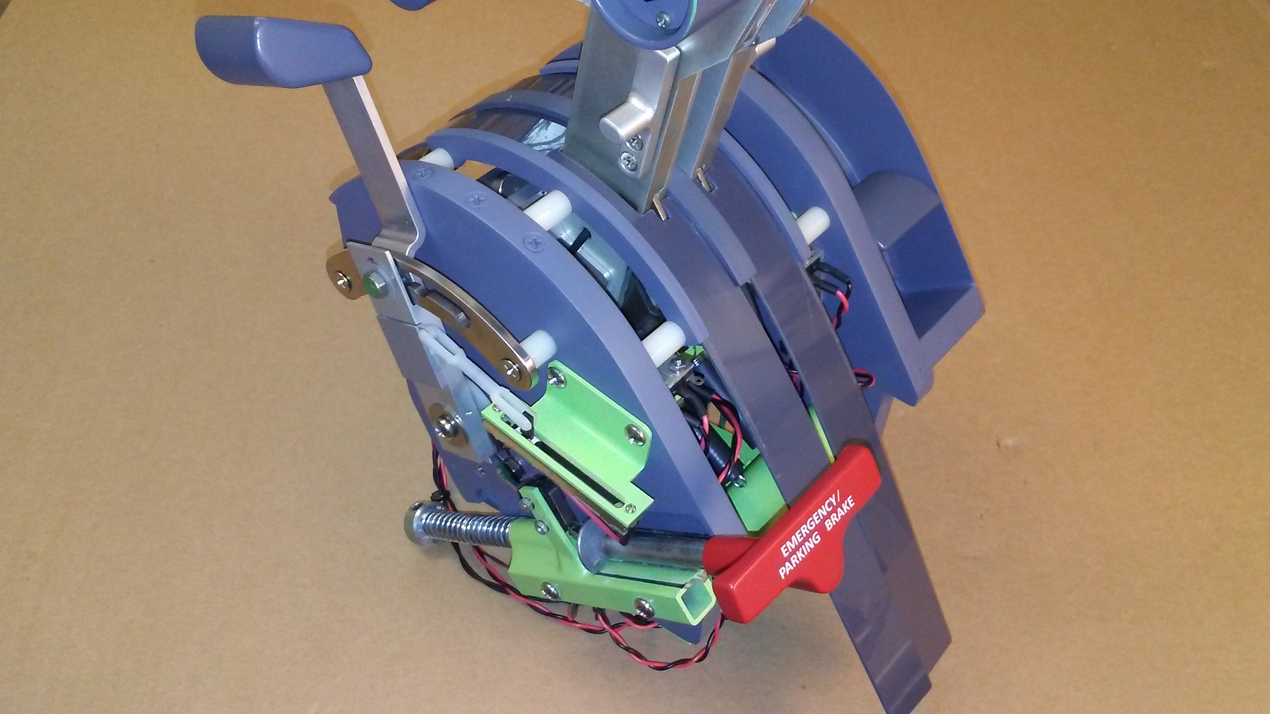
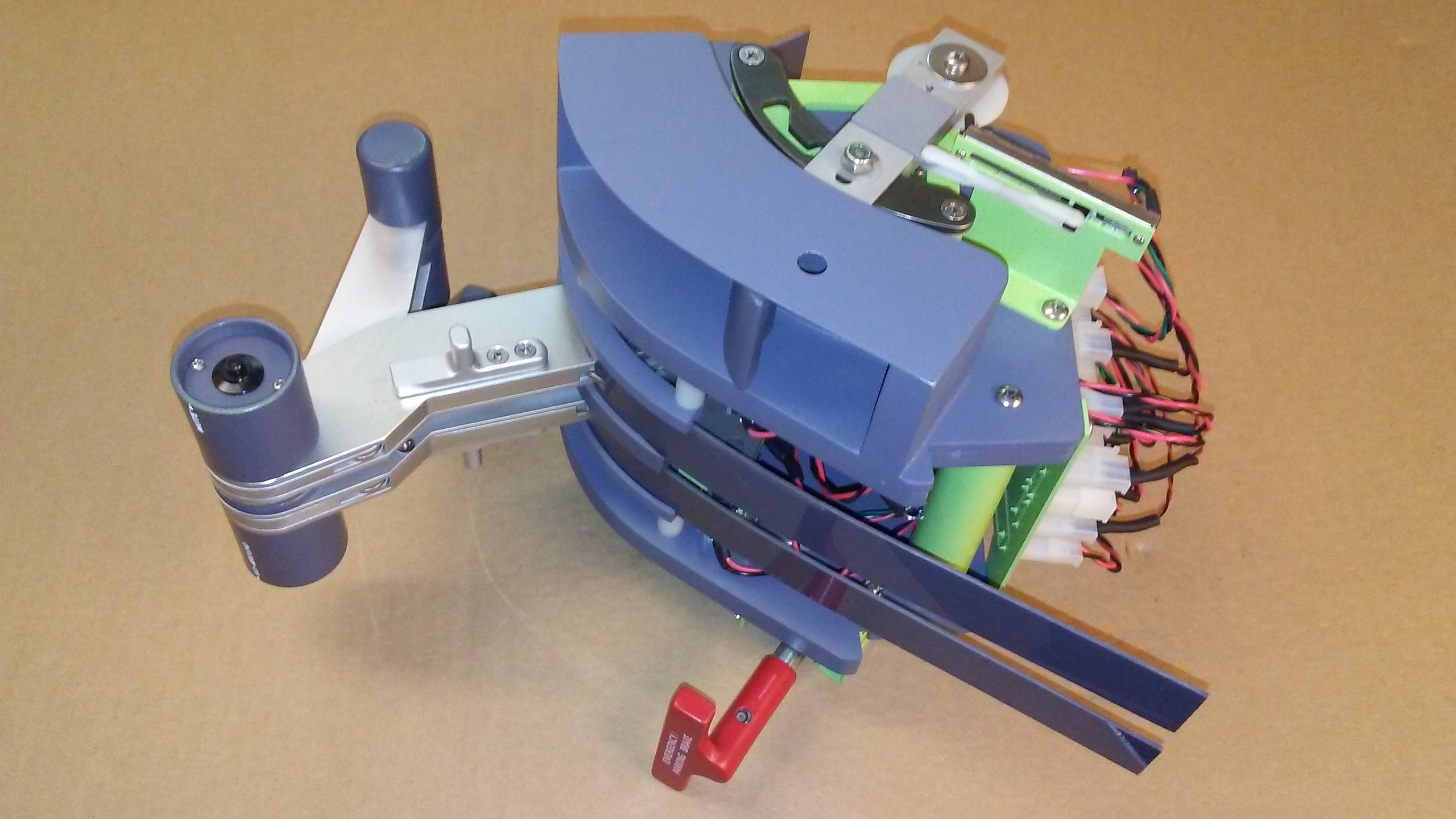
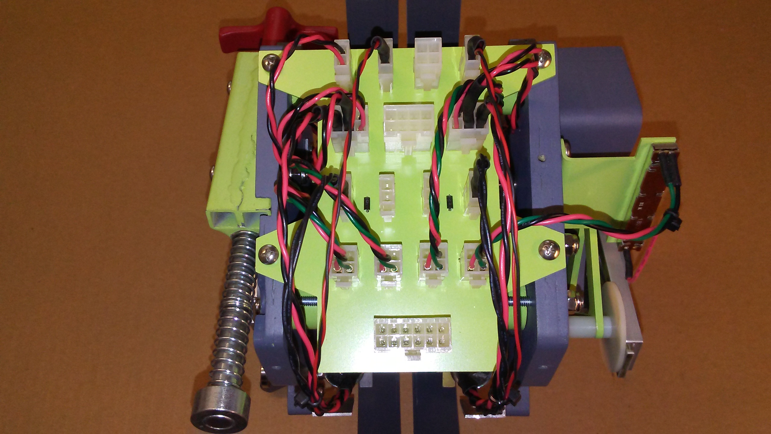
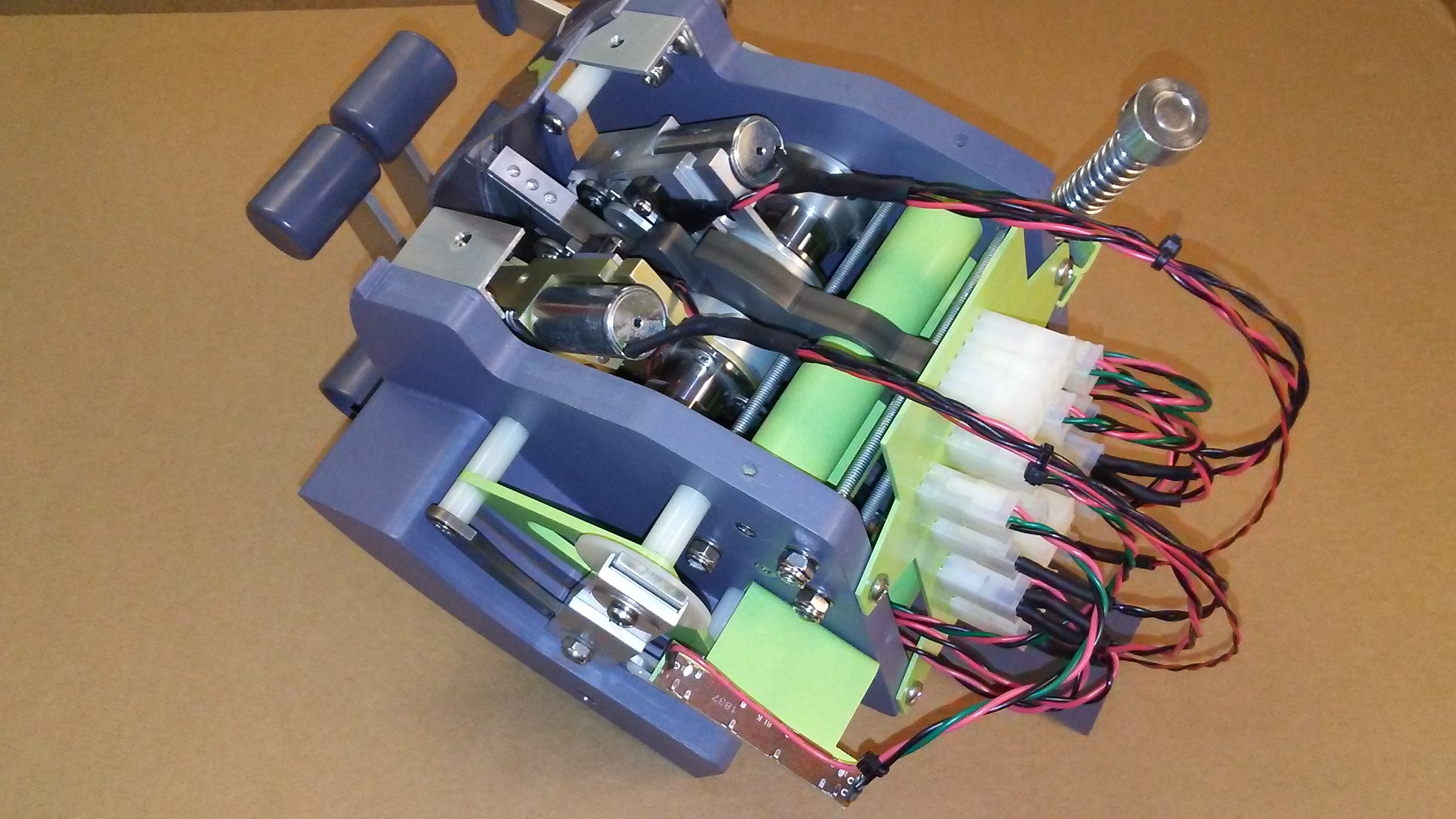
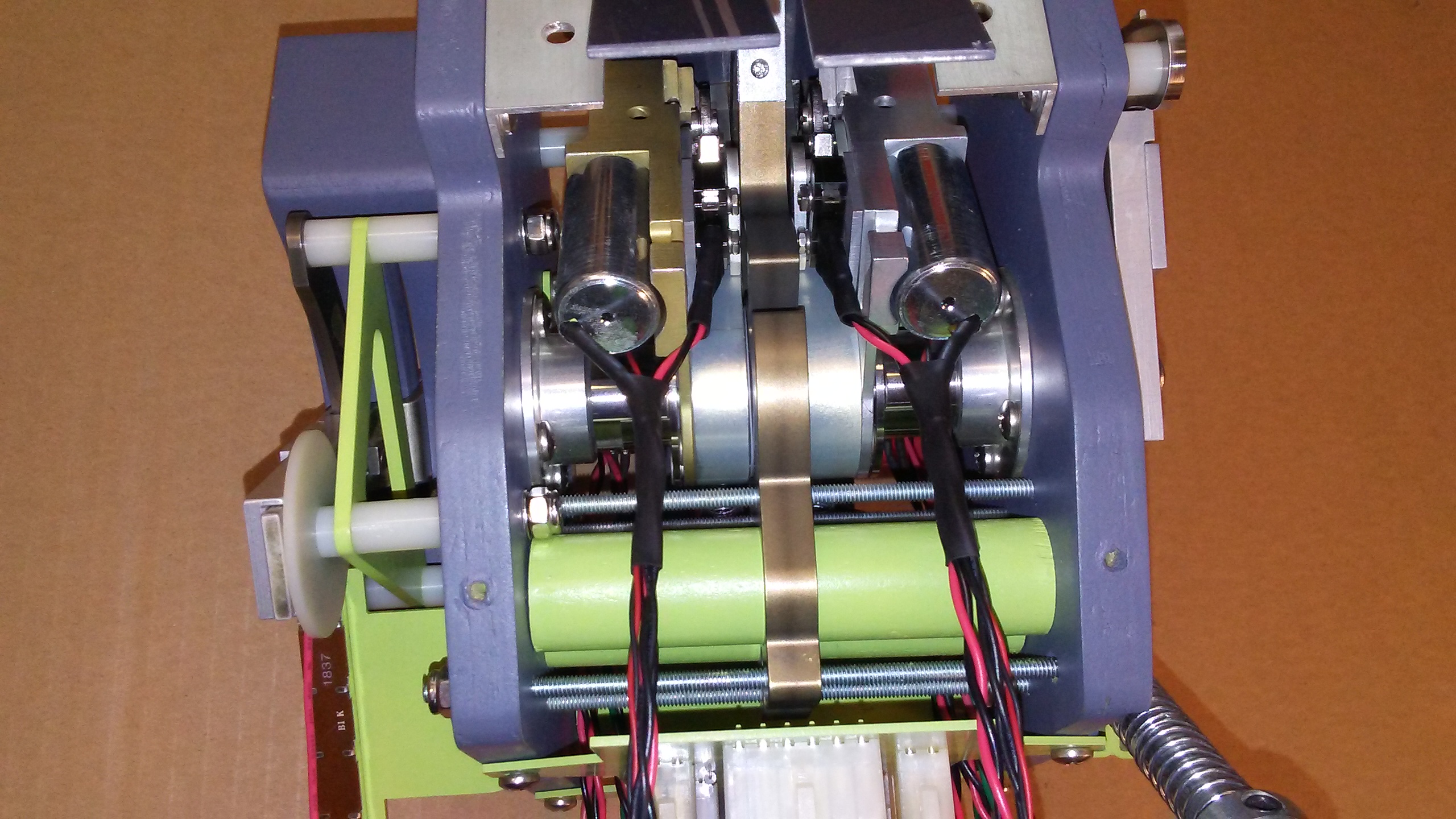
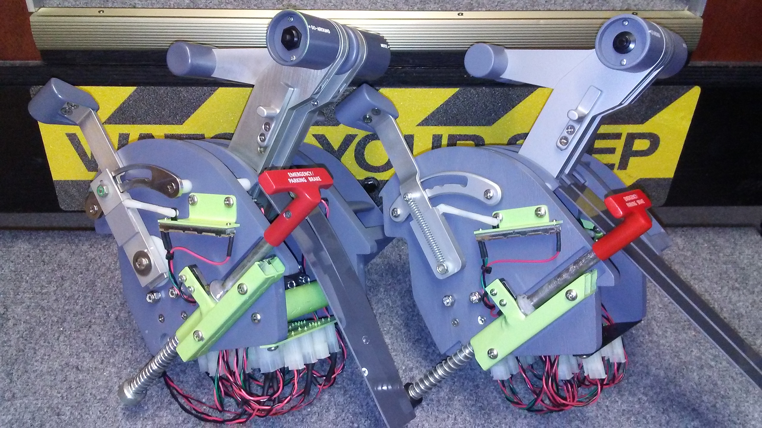
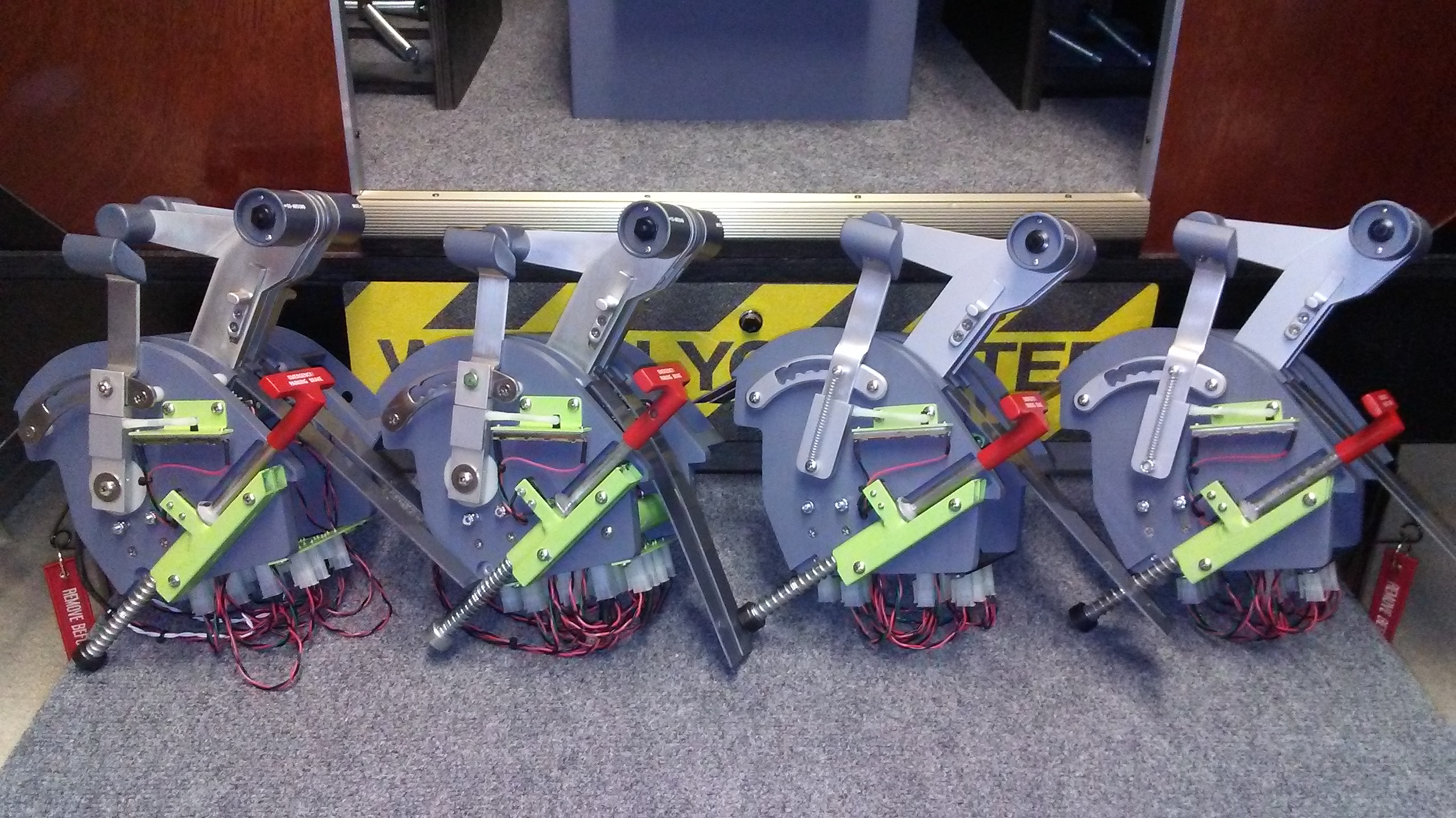
Hey guys, I am finally finishing up with the TQ modules that use real parts and the replicas. Today I did the final assembly of my own TQ module and wanted to post up the photos for future reference. The major updates to this TQ module was the addition of the reverse solenoid, reverse lockout pins, associated switches, the wire management board and the flaps brace with associated parts. Here are the finalized photos: Even the parking brake handle got a bit of a makeover. New paint and new professional dry transfers with a satin clear coat finish! Note that I used extra shrink tube on all the wires that are attached to the levers. Moving the levers back and forth will eventually cause the wires to fail at the solder joints unless they are protected. I had a couple failures in the past and learned the hard way! This photo shows all three major additions, the reverse solenoids, the flaps brace and the wire management board. Note the bundle of wires coming out from the bottom of the solenoids. This is a great look at two sets of wires that move with the movement of the thrust levers. A large unimpeded loop does the trick: Once the TQ module is assembled, it is difficult to see the complexity of the moving parts inside. As an example, there is no way to take a photo of what I call the "missing link". You would have to refer back to one of my earlier photos to see it: Here is a neat photo of both TQ modules setting side by side. Mine, the one on the left has real TQ parts in it including the thrust levers, spoiler and flaps. The one on the right is made of 100% replica parts! I have two available as of this date, Jan 15th 2019: Mark, I should have your TQ module completed in the next week or so once I get your parking brake assembly from Shane. He is just about finished with a small batch of them. Your gonna love the new TQ module! If anyone has any questions or is interested in one of the TQ module replicas, you can either post here or email me at ronjonrollo@yahoo.com Hey guys, I am finally finishing up with the TQ modules that use real parts and the replicas. Today I did the final assembly of my own TQ module and wanted to post up the photos for future reference. The major updates to this TQ module was the addition of the reverse solenoid, reverse lockout pins, associated switches, the wire management board and the flaps brace with associated parts. Here are the finalized photos: Even the parking brake handle got a bit of a makeover. New paint and new professional dry transfers with a satin clear coat finish! Note that I used extra shrink tube on all the wires that are attached to the levers. Moving the levers back and forth will eventually cause the wires to fail at the solder joints unless they are protected. I had a couple failures in the past and learned the hard way! This photo shows all three major additions, the reverse solenoids, the flaps brace and the wire management board. Note the bundle of wires coming out from the bottom of the solenoids. This is a great look at two sets of wires that move with the movement of the thrust levers. A large unimpeded loop does the trick: Once the TQ module is assembled, it is difficult to see the complexity of the moving parts inside. As an example, there is no way to take a photo of what I call the "missing link". You would have to refer back to one of my earlier photos to see it: Here is a neat photo of both TQ modules setting side by side. Mine, the one on the left has real TQ parts in it including the thrust levers, spoiler and flaps. The one on the right is made of 100% replica parts! I have two available as of this date, Jan 15th 2019: Mark, I should have your TQ module completed in the next week or so once I get your parking brake assembly from Shane. He is just about finished with a small batch of them. Your gonna love the new TQ module! If anyone has any questions or is interested in one of the TQ module replicas, you can either post here or email me at ronjonrollo@yahoo.com Those look really good. Hard to tell the replica from the real parts! Those look really good. Hard to tell the replica from the real parts! Ron, I can't thank you and Shane enough for the magnificent job on my real TQ. I have been using Mark L's TQ for possibly around 5 years now. I can tell you that it has been flogged with many of the hundreds of flights myself and my aircrew have put it through. It's war wounds now make for some 'hairy' landings when the reverse thrusters are now mismatched with the L at around 78% and the R maxed out at 45%. My brain has now adapted to landing with intermittent tapping of the R brake to stay on the runway ! The crew are really looking forward to installing and flying with the new, more robust TQ. I just want to re-iterate to our builders that your hard work building is amply paid back in spades from the fun you will have flying , especially when you have your mates around. Every fortnight I host a mission for my two aircrew, Peter Nicholas and Mark Cooper. Last Wed. night I had them fly from Israel to Lebanon and then on to Cyprus. Why ? Because the three countries you can download the photoreal scenery for free. Also it is not a choice of countries we would normally fly or holiday to. That is also one of the wonderful things that this hobby will give you, giving you a new perspective to see and learn about other countries in the world. You all know my story now because I am upgrading my TQ ! Cheers all, keep building and thanks again to Ron and Shane. Mark S. (Speechley) Ron, I can't thank you and Shane enough for the magnificent job on my real TQ. I have been using Mark L's TQ for possibly around 5 years now. I can tell you that it has been flogged with many of the hundreds of flights myself and my aircrew have put it through. It's war wounds now make for some 'hairy' landings when the reverse thrusters are now mismatched with the L at around 78% and the R maxed out at 45%. My brain has now adapted to landing with intermittent tapping of the R brake to stay on the runway ! The crew are really looking forward to installing and flying with the new, more robust TQ. I just want to re-iterate to our builders that your hard work building is amply paid back in spades from the fun you will have flying , especially when you have your mates around. Every fortnight I host a mission for my two aircrew, Peter Nicholas and Mark Cooper. Last Wed. night I had them fly from Israel to Lebanon and then on to Cyprus. Why ? Because the three countries you can download the photoreal scenery for free. Also it is not a choice of countries we would normally fly or holiday to. That is also one of the wonderful things that this hobby will give you, giving you a new perspective to see and learn about other countries in the world. You all know my story now because I am upgrading my TQ ! Cheers all, keep building and thanks again to Ron and Shane. Mark S. (Speechley) Thanks Mark for the kinds words! All I can say is you guys down under are going to love the new TQ module. Not just for it's robust feel, but also for it's enhanced features. It will take a day or two to get it wired in and set up though. But you will be the first ever to use these new reverse lockout features in the Hangar! Yesterday I received a package from Shane that included three parking brake assembles so now I am free to finish the sets I have started. Mark, your TQ will be completed by next Friday! Thanks Mark for the kinds words! All I can say is you guys down under are going to love the new TQ module. Not just for it's robust feel, but also for it's enhanced features. It will take a day or two to get it wired in and set up though. But you will be the first ever to use these new reverse lockout features in the Hangar! Yesterday I received a package from Shane that included three parking brake assembles so now I am free to finish the sets I have started. Mark, your TQ will be completed by next Friday! Okay guys, I can finally say I am complete with the TQ modules whether they are replicas or the ones that use real parts. Today I put the final finishing touches on Mark's TQ and finished up the last replica. This photo below shows two completed TQ modules using real parts on the left and two replica TQ modules on the right: This photo represents months of tedious work, not to mention the two TQ modules that I shipped out to Jason and Maciej! Now I am free to move on to other aspects of the project. If you need one or have any questions about the TQ module and how it operates, please post your questions here. Okay guys, I can finally say I am complete with the TQ modules whether they are replicas or the ones that use real parts. Today I put the final finishing touches on Mark's TQ and finished up the last replica. This photo below shows two completed TQ modules using real parts on the left and two replica TQ modules on the right: This photo represents months of tedious work, not to mention the two TQ modules that I shipped out to Jason and Maciej! Now I am free to move on to other aspects of the project. If you need one or have any questions about the TQ module and how it operates, please post your questions here. Great to see the TQ replica line ready for builders! Great to see the TQ replica line ready for builders! Ron, The TQ just arrived today. The detail is absolutely amazing. I'll get on and get the interface harness wiring completed and then report back. Mark Ron, The TQ just arrived today. The detail is absolutely amazing. I'll get on and get the interface harness wiring completed and then report back. Mark How to program the Reverse Lockout Solenoids and switches: Now that Mark Speechley has a TQ module with real parts and the new reverse lockout solenoids, it is time to post up some instructions on how to program this system properly. Mark will be the first to actually use this new design and I for one am looking forward to seeing a short video of the new system in action. So lets see if I can explain the programming process clearly......or not. First you need to have the correct interface cards. We recommend the FDS SYS cards and the FDS Relay cards from Flight Deck Solution. They are a little expensive but well worth the money and easy to program. Both of these cards and all the other cards in the SYS family use a program called InterfaceIT to manage all the settings, offsets and internal variables. If you do not have FDS cards, other similar interface cards will work but the process outlined below might be a little different. While I am talking about relay cards, the FDS Relays cards have eight relays each. As our Lear45 projects have grown over the past few years, we have finally got to the point that we need two relay cards with eight relays each. I recommend dividing the airplane in two, Left side and Right side relay buses. You will end up with a few unused relays but in time we will use them all! So the first thing you need to do is wire the two Reverser Lockout Switches to the FDS SYS card. You will want to label them in the InterfaceIT software program as L Reverse Lockout and R Reverse Lockout. Take a close look at your TQ module and with the thrust levers in the Idle position or higher, try to pull back on the reverser levers. You will notice that you can not pull them back very far, BUT, if you look and listen really close, you will see and hear each of the Reverse Lockout Switches activating. These switches send signals back to the InterfaceIT software basically asking permission to activate the solenoids.......or not. So you will need to assign to each of these Reverse Lockout Switches in the InterfaceIT software a few things: You will want to create two internal variables respectively called L Reverse Lockout and R Revrse Lockout. IF all conditions listed below are met, the internal variables will trigger the solenoid relays to the perspective reverser which will allow you to pull the reverse levers past the mechanical lock linkage and all the way back at which point ANOTHER switch is triggered. This second switch activates the reversers which deploys your reverser buckets and slows the airplane down. Think of the first Reverse Lockout Switches as the "gate keepers" to the Reverser Switches. (Please note that sometime I am referring to one reverser, switch and solenoid and other times to both. You will have to set up a left and a right reverser with associated components totally separated from each other.) Those conditions that need to be met are: 1. Weight On Wheels offset (These others are not as important but you can try programing them if you like) Now that we have established the Reverse Lockout Switches we can now figure out how to program the solenoid relays to each of the reverse lockouts. The solenoids require 12 volt power to operate. You can bench test them with a new 9 volt battery to see them actuate and work the mechanical linkages. You will want to run the ground lines through the relays on the FDS relay card. In other words, you will use the relays to break the grounds and when the internal variable relays receive the go ahead from the Reverse Lockout internal variables, it will close the relays which will allow the circuits to close and actuate the solenoids. So at this point, believe it or not, the reversers have still not deployed! You have to continue to pull the physical reverse handles back past the mechanical locks and then they will finally hit the last switches. These last switches are the Reverser Switches. These switches are what you should already have working in your current TQ module. We just had to jump through a few hoops to get to this point! All this hard work is so that the reversers CAN NOT be deployed in flight. (Actually, the flight simulator will not allow the reversers to be deployed in flight.) So to rephrase, all this hard work so that the physical reverser levers can not be pulled back while in flight or when those few conditions are not met. One thing to keep in mind, we do not want the solenoids energized for extended periods of time. Five to ten seconds is fine and normal. What we do not want is the solenoids energized for longer periods of time. They will generate heat and emit Electromagnetic Interference (EMI) throughout the cockpit which could cause certain interface cards to kick off line. With that said, I do have two 470 uF capacitors built into the wire management board to capture that energy and keep it isolated at the solenoid. If you wire and program everything as I have designed, you will not have to worry about this. The solenoids will only activate when you are using them. During a typical flight simulation period, they will only be energized for a few seconds at touchdown during landings! And that is it in a nutshell. If anyone has any questions please post here. Looking forward to hearing back from Mark and seeing his TQ module in action! How to program the Reverse Lockout Solenoids and switches: Now that Mark Speechley has a TQ module with real parts and the new reverse lockout solenoids, it is time to post up some instructions on how to program this system properly. Mark will be the first to actually use this new design and I for one am looking forward to seeing a short video of the new system in action. So lets see if I can explain the programming process clearly......or not. First you need to have the correct interface cards. We recommend the FDS SYS cards and the FDS Relay cards from Flight Deck Solution. They are a little expensive but well worth the money and easy to program. Both of these cards and all the other cards in the SYS family use a program called InterfaceIT to manage all the settings, offsets and internal variables. If you do not have FDS cards, other similar interface cards will work but the process outlined below might be a little different. While I am talking about relay cards, the FDS Relays cards have eight relays each. As our Lear45 projects have grown over the past few years, we have finally got to the point that we need two relay cards with eight relays each. I recommend dividing the airplane in two, Left side and Right side relay buses. You will end up with a few unused relays but in time we will use them all! So the first thing you need to do is wire the two Reverser Lockout Switches to the FDS SYS card. You will want to label them in the InterfaceIT software program as L Reverse Lockout and R Reverse Lockout. Take a close look at your TQ module and with the thrust levers in the Idle position or higher, try to pull back on the reverser levers. You will notice that you can not pull them back very far, BUT, if you look and listen really close, you will see and hear each of the Reverse Lockout Switches activating. These switches send signals back to the InterfaceIT software basically asking permission to activate the solenoids.......or not. So you will need to assign to each of these Reverse Lockout Switches in the InterfaceIT software a few things: You will want to create two internal variables respectively called L Reverse Lockout and R Revrse Lockout. IF all conditions listed below are met, the internal variables will trigger the solenoid relays to the perspective reverser which will allow you to pull the reverse levers past the mechanical lock linkage and all the way back at which point ANOTHER switch is triggered. This second switch activates the reversers which deploys your reverser buckets and slows the airplane down. Think of the first Reverse Lockout Switches as the "gate keepers" to the Reverser Switches. (Please note that sometime I am referring to one reverser, switch and solenoid and other times to both. You will have to set up a left and a right reverser with associated components totally separated from each other.) Those conditions that need to be met are: 1. Weight On Wheels offset (These others are not as important but you can try programing them if you like) Now that we have established the Reverse Lockout Switches we can now figure out how to program the solenoid relays to each of the reverse lockouts. The solenoids require 12 volt power to operate. You can bench test them with a new 9 volt battery to see them actuate and work the mechanical linkages. You will want to run the ground lines through the relays on the FDS relay card. In other words, you will use the relays to break the grounds and when the internal variable relays receive the go ahead from the Reverse Lockout internal variables, it will close the relays which will allow the circuits to close and actuate the solenoids. So at this point, believe it or not, the reversers have still not deployed! You have to continue to pull the physical reverse handles back past the mechanical locks and then they will finally hit the last switches. These last switches are the Reverser Switches. These switches are what you should already have working in your current TQ module. We just had to jump through a few hoops to get to this point! All this hard work is so that the reversers CAN NOT be deployed in flight. (Actually, the flight simulator will not allow the reversers to be deployed in flight.) So to rephrase, all this hard work so that the physical reverser levers can not be pulled back while in flight or when those few conditions are not met. One thing to keep in mind, we do not want the solenoids energized for extended periods of time. Five to ten seconds is fine and normal. What we do not want is the solenoids energized for longer periods of time. They will generate heat and emit Electromagnetic Interference (EMI) throughout the cockpit which could cause certain interface cards to kick off line. With that said, I do have two 470 uF capacitors built into the wire management board to capture that energy and keep it isolated at the solenoid. If you wire and program everything as I have designed, you will not have to worry about this. The solenoids will only activate when you are using them. During a typical flight simulation period, they will only be energized for a few seconds at touchdown during landings! And that is it in a nutshell. If anyone has any questions please post here. Looking forward to hearing back from Mark and seeing his TQ module in action! I have just started wiring my new TQ. In order to interface with windows you will need a card to attach the potentiometers to, four in total. The recommended card is the Leo Bodnar. Here are two choices. http://www.leobodnar.com/shop/index.php?main_page=product_info&cPath=94&products_id=180 or http://www.leobodnar.com/shop/index.php?main_page=product_info&cPath=94&products_id=204 I have 2 Pokey 56U cards spare, so I have attached part of the TQ ( flaps,throttles and spoiler potentiometers) to one of the cards. I contacted Polabs for advice and here is their reply. Hi, Mark Make sure that you always use the 3.3 V - connecting a voltage signal higher than that to analog input pin on PoKeys device, the device can be damaged. You can wire all those potentiometers in parallel to +3.3V and GND pins. So far it has worked on the test bench, so stay tuned to see once fully installed, that we may have more options. Mark S. I have just started wiring my new TQ. In order to interface with windows you will need a card to attach the potentiometers to, four in total. The recommended card is the Leo Bodnar. Here are two choices. http://www.leobodnar.com/shop/index.php?main_page=product_info&cPath=94&products_id=180 or http://www.leobodnar.com/shop/index.php?main_page=product_info&cPath=94&products_id=204 I have 2 Pokey 56U cards spare, so I have attached part of the TQ ( flaps,throttles and spoiler potentiometers) to one of the cards. I contacted Polabs for advice and here is their reply. Hi, Mark Make sure that you always use the 3.3 V - connecting a voltage signal higher than that to analog input pin on PoKeys device, the device can be damaged. You can wire all those potentiometers in parallel to +3.3V and GND pins. So far it has worked on the test bench, so stay tuned to see once fully installed, that we may have more options. Mark S. Hi all, Well Coop and I can finally say that we have completed the reversers on our 'real parts' throttle quadrant. It has been a little challenging wiring the plugs and dealing with Interface IT and FSUIPC. The biggest challenge has been the offsets. For those of you who have not delved into that yet, you will have a new subset of learning ahead. In some situations you will have more than one choice of offset, or you may need to include more than one offset for the required event, so it is a matter of trial and error. When we have completed the final testing of the other TQ components, Park Brake and Cutoff, then we will write up a list of the required offsets for those who may require them and add them to this thread. Sometimes Peter Dowson the author of FSUIPC, can be a bit 'Einstein-ish" when describing an offset or parameter, especially if it all seems gobbledygook to start with. Or is that just us.....hmmm ? Anyway here is the 2 part video of the TQ in action. The first part is the Reverser Lockout switch preventing the Reversers from working whilst flying. The second is the Reverser lockout switch allowing the solenoids to activate to allow the Reverser switch to enable the Reversers to function. The 'plane on the ground' offset 'IS' required and hence if you listen you will hear the switch kick in and out as the plane kangaroo hops on the runway, finally allowing the reversers to kick in. Ron. Your dream is alive. Congratulations. https://youtu.be/XOAt_EMukFo Regards Captains Mark Speechley and Mark Cooper Pacifica Oceania LJ45 aircrew. Hi all, Well Coop and I can finally say that we have completed the reversers on our 'real parts' throttle quadrant. It has been a little challenging wiring the plugs and dealing with Interface IT and FSUIPC. The biggest challenge has been the offsets. For those of you who have not delved into that yet, you will have a new subset of learning ahead. In some situations you will have more than one choice of offset, or you may need to include more than one offset for the required event, so it is a matter of trial and error. When we have completed the final testing of the other TQ components, Park Brake and Cutoff, then we will write up a list of the required offsets for those who may require them and add them to this thread. Sometimes Peter Dowson the author of FSUIPC, can be a bit 'Einstein-ish" when describing an offset or parameter, especially if it all seems gobbledygook to start with. Or is that just us.....hmmm ? Anyway here is the 2 part video of the TQ in action. The first part is the Reverser Lockout switch preventing the Reversers from working whilst flying. The second is the Reverser lockout switch allowing the solenoids to activate to allow the Reverser switch to enable the Reversers to function. The 'plane on the ground' offset 'IS' required and hence if you listen you will hear the switch kick in and out as the plane kangaroo hops on the runway, finally allowing the reversers to kick in. Ron. Your dream is alive. Congratulations. Regards Captains Mark Speechley and Mark Cooper Pacifica Oceania LJ45 aircrew.Throttle Quadrant Module by Project45
![]()
![]()
![]()
![]()
![]()
![]()
![]()
![]()
2. Engine running
3. Oil pressure to that engine
4. No fire detected in that engine
2. Engine running
3. Oil pressure to that engine
4. No fire detected in that engine![]()
Anyway, regarding your question - each potentiometer should have 3 leads: two for the resistor and one for the wiper. Wire the resistor leads (usually the first and last one) to GND and +3.3V, respectively. Wire the wiper lead (usually the middle one) to analog input.
Wiring of one or multiple potentiometers is the same. Make sure that you correctly identify the function of the leads.
Anyway, regarding your question - each potentiometer should have 3 leads: two for the resistor and one for the wiper. Wire the resistor leads (usually the first and last one) to GND and +3.3V, respectively. Wire the wiper lead (usually the middle one) to analog input.
Wiring of one or multiple potentiometers is the same. Make sure that you correctly identify the function of the leads. ![]()
Forum NavigationThrottle Quadrant Module by Project45
![]() #21 · January 15, 2019, 7:07 pm
#21 · January 15, 2019, 7:07 pm![]() #22 · January 18, 2019, 10:17 pm
#22 · January 18, 2019, 10:17 pm![]() #23 · January 25, 2019, 4:34 am
#23 · January 25, 2019, 4:34 am![]() #24 · January 25, 2019, 7:11 am
#24 · January 25, 2019, 7:11 am![]() #25 · February 6, 2019, 12:03 pm
#25 · February 6, 2019, 12:03 pm![]() #26 · February 8, 2019, 8:14 pm
#26 · February 8, 2019, 8:14 pm![]() #27 · February 17, 2019, 11:19 pm
#27 · February 17, 2019, 11:19 pm![]() #28 · February 21, 2019, 8:15 pm
#28 · February 21, 2019, 8:15 pm![]() #29 · February 27, 2019, 8:47 am
#29 · February 27, 2019, 8:47 am![]() #30 · May 4, 2019, 5:52 am
#30 · May 4, 2019, 5:52 am
2017-10-10