


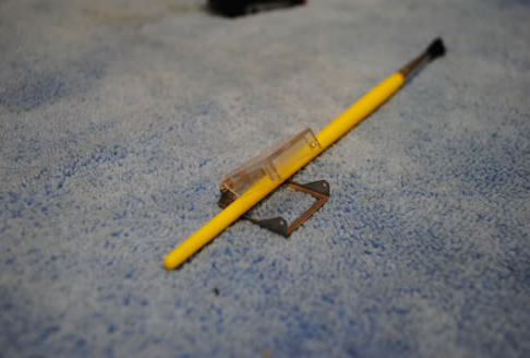
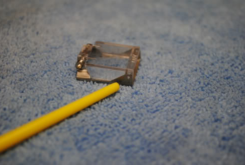
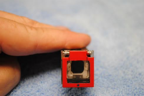
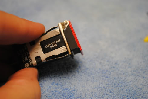
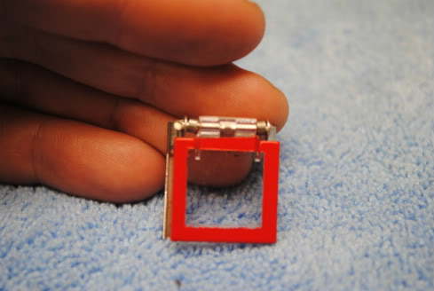
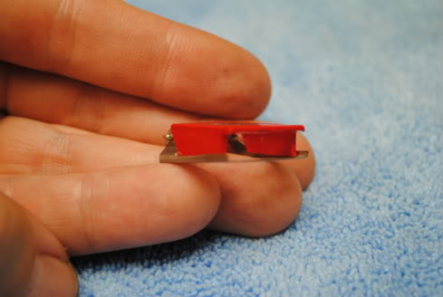
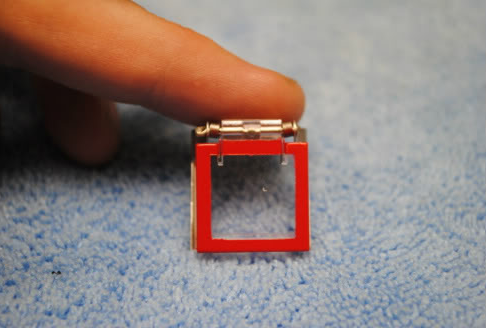
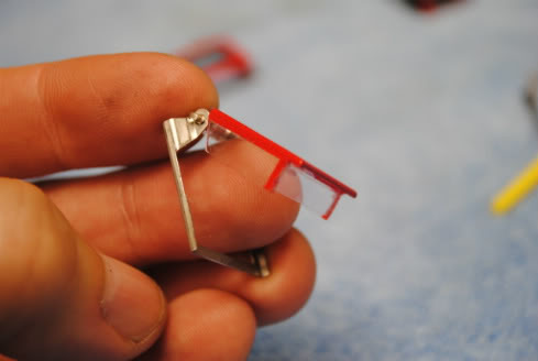
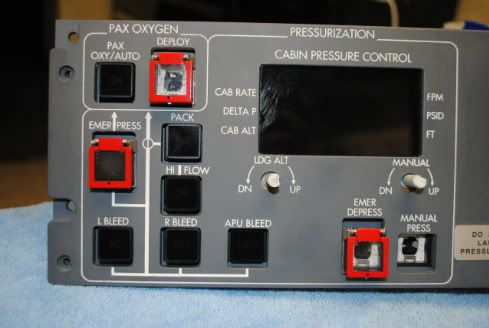
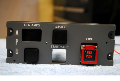
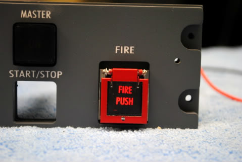
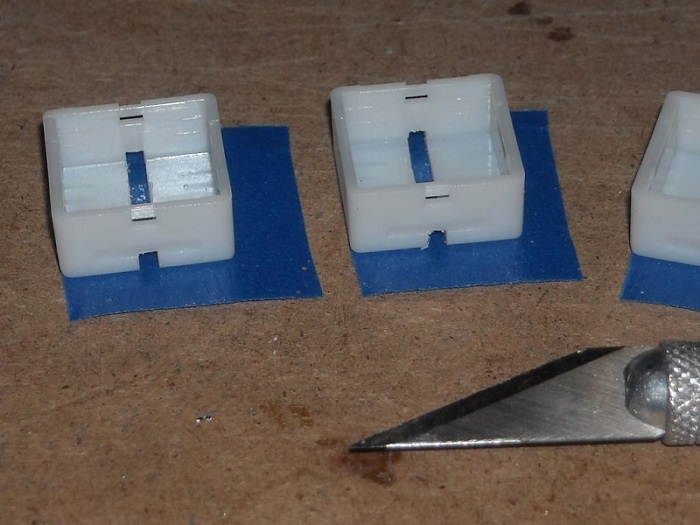
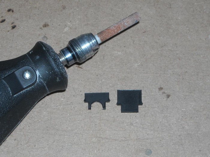
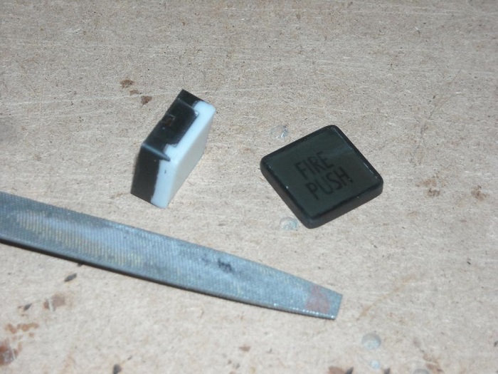
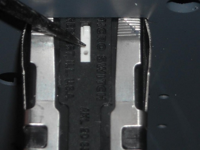
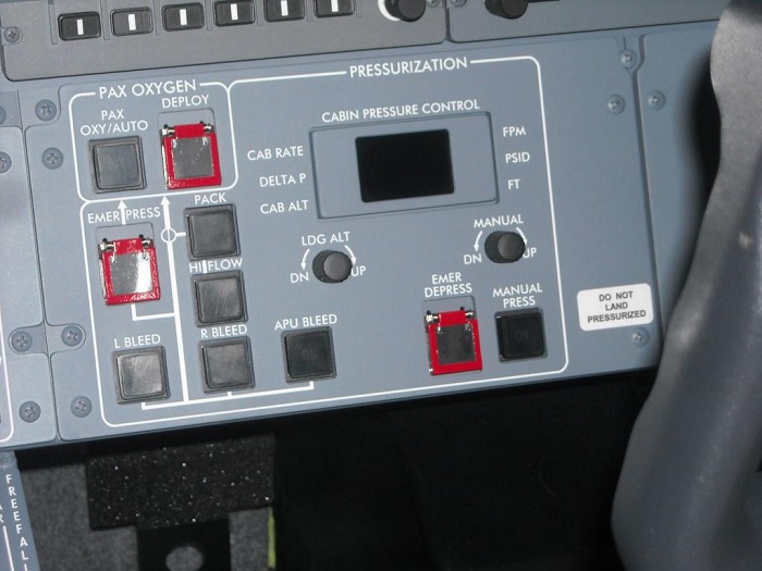
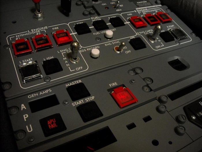
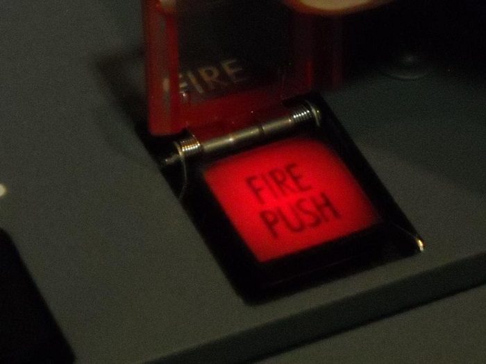
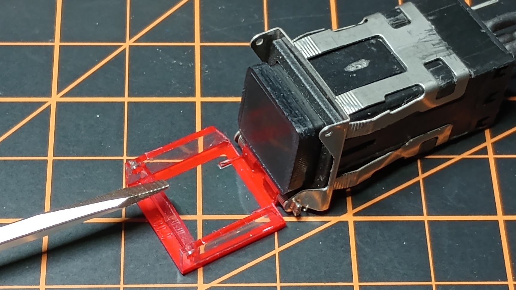
(Original thread started on 10-10-11 by Shane Barnes) Ron emailed me a few days ago and asked about the AML switch guard and whether it would work for our projects. I have been looking for a cost effective way to modify the existing AML switch guard and have found a cheap solution. With a few simple mods to the AML guard it can look the part of the guards in the Lear. The mods require a little work with a Dremel tool and some masking and painting but this is one of those projects that you can do over a couple of nights and CHEAP! I was very satisfied with the results and this is what I will be using in my build. First off here is a photo of the switch guard in question, the AML 76C10TO1P. You can currently purchase this guard at the following site for $2.99. I found mine on eBay HERE This is the switch guard prior to any modification: The first modification is to grind off the "locking tabs" from the front of the metal attachment. The yellow paintbrush is pointing to this area in the photo below. This will be done to all of the guards: The first switch guard that I modified was the guards for the pressure panel. You will need to drill a 1/16 inch hole in the top of the guard as shown in the photo to duplicate the one found in the Lear. You will only do this for the three guards on the pressure panel and the one guard for the APU panel: The next step is to look at the side of the switch and note two holes that are drilled so the switch cap could be locked down (this aligns with the locking tabs that were removed earlier) This area needs to be removed with a Dremel so what you are left with is a lip on the front of the switch guard. You will do this for all of the switch guards: The top of the guard is taped off to form a square to protect the clear plastic. The complete top of the guard is painted red. The three sides (or what I call walls) are painted a flat black. You will notice in the photo that a small stripe of red is painted on the sides approximately 1/16 inch or a little more. The next switch guard is the fire guard located on the start panel. This switch is taped off in a similar fashion however the whole top of the switch does not get painted. Look at the following photo to reference what areas get painted: The front "wall" of this switch gets removed with the Dremel tool. Be careful not to scuff the clear plastic area that will show after painting. After removing the front wall you will paint the two side walls red. In this photo you can see the side walls painted red and the front wall removed: The next guard is the guard located over the extinguisher switches. There are four of these total. Here is a photo of the top of the switch that will show you what area to paint: The side of the switch is painted a little different in that only a small stripe is painted near the front wall on each side. This photo will better demonstrate the paint scheme: Here is a photo of the pressure panel switch guards mounted. The far left guard has a different switch cap mounted. Can you see any difference? (Posted by Eric Tomlin on 10-11-11) Thank you Shane, this is an excellent tutorial. A few months ago when I began the final design for the panels with guards, I knew that there had to be a suitable "COTS" solution (COTS= Commercial Off The Shelf) that did not require me to sit down and pain stakenly design a new cover for the upcoming panels from Flight Level Simulations. Shane and I got to talking and we both came to the conclusion that when the guard is 'down' then you cannot tell that the switch cap is not the actual Chromalux 389 size (which is in fact, only a tiny bit larger than the standard AML21 style cap to begin with) and that it would be silly to not use these when it was such a simple solution. I placed an order of the smoked gray caps and once they are under the switch guard, they look every bit the part. This solution provides several advantages to both the customer and to myself as a vendor: • Easily purchased/modded by the builder • Fits perfectly onto the AML21 switch body • Cost remains low due to no new R&D by myself. A huge thanks goes to Shane for taking the time to sit down and determine the three different variants and what modifications are due to them to give that near-perfect appearance. When he first showed me a photo back during our initial investigation, I was truly wowed and I knew that we had worked out a very good compromise between functionality, appearance, and ease of implementation. I am currently awaiting the inserts to arrive with the proper legend placed on them for these particular guarded switches. The long answer: The AML71 switch guard/cover is an excellent solution because: • They are commercially available off the shelf, no production required from me • They fit the AML21 switch and are very secure; no problems mounting to the panel or backer • They are more affordable purchased online than what I could ever make them for The short answer: It's best for the customer to buy/mod/paint these; the time and effort for me to do this would likely be cost prohibitive for folks. (Posted by Shane Barnes on 10-11-11) Thanks guys. I wanted something cheap, easy to mod by the builder, looked like the part and functioned like the real part with the incorporated spring return action and this fit the bill. It also fits the AML as originally designed so no further fabrication needed. This is one of those projects that you can order up the parts and have completed in a couple of nights. I am sure that you guys will come up with even more mods to this cheap solution that will make it even better. We need twelve of these in our project! Ten of them will be modified and painted and two will be used as is. The two used as is are for the start switches. Posted by Eric Williams on 10-29-11) Hey Shane- is it true our existing caps will not fit under these? I am getting conflicting stories that the 389 replicas are no good when a person uses these. If so- where did you find someone to laser the new cap etc? Care to share the company so we can get our own done? Eric T indicated yesterday that he would NOT commercially supply any of this, so I could use some info on getting my own made. Posted by Eric Tomlin on 10-29-11) I'm not sure where you get conflicting stories from. Both Shane and I have openly explained how these work in detail. On the switches that use the AML7x switch guard, you *cannot* use the 389 ring and lens- they simply won't fit under the guard. Therefore you must use a standard AML21C cap of the smoke gray type, which provides the very same dead front for the laser engraved inserts until illuminated. These laser engraved inserts are simply the standard white insert painted black and then engraved by the same vendor used for the panels. Also, I never said that I would NOT provide these, but that they would be cost prohibitive to most folks and that was to imply that it'd be cheaper for the builder to mod/paint themselves. If anyone wants me to provide these, they can email me for a quote but most folks will likely pass because modding these will take more time away from making/providing the parts that can't be done at anyone's work bench like the guards can be. As Shane indicated, they're not HARD to make, just time consuming and if I have to take 10-12 hours to do all 12, then it gets expensive really quick. Also, I'd be more than glad to get these engraved for you Eric or anyone else, just email me for a quote. (Original thread started on 10-10-11 by Shane Barnes) Ron emailed me a few days ago and asked about the AML switch guard and whether it would work for our projects. I have been looking for a cost effective way to modify the existing AML switch guard and have found a cheap solution. With a few simple mods to the AML guard it can look the part of the guards in the Lear. The mods require a little work with a Dremel tool and some masking and painting but this is one of those projects that you can do over a couple of nights and CHEAP! I was very satisfied with the results and this is what I will be using in my build. First off here is a photo of the switch guard in question, the AML 76C10TO1P. You can currently purchase this guard at the following site for $2.99. I found mine on eBay HERE This is the switch guard prior to any modification: The first modification is to grind off the "locking tabs" from the front of the metal attachment. The yellow paintbrush is pointing to this area in the photo below. This will be done to all of the guards: The first switch guard that I modified was the guards for the pressure panel. You will need to drill a 1/16 inch hole in the top of the guard as shown in the photo to duplicate the one found in the Lear. You will only do this for the three guards on the pressure panel and the one guard for the APU panel: The next step is to look at the side of the switch and note two holes that are drilled so the switch cap could be locked down (this aligns with the locking tabs that were removed earlier) This area needs to be removed with a Dremel so what you are left with is a lip on the front of the switch guard. You will do this for all of the switch guards: The top of the guard is taped off to form a square to protect the clear plastic. The complete top of the guard is painted red. The three sides (or what I call walls) are painted a flat black. You will notice in the photo that a small stripe of red is painted on the sides approximately 1/16 inch or a little more. The next switch guard is the fire guard located on the start panel. This switch is taped off in a similar fashion however the whole top of the switch does not get painted. Look at the following photo to reference what areas get painted: The front "wall" of this switch gets removed with the Dremel tool. Be careful not to scuff the clear plastic area that will show after painting. After removing the front wall you will paint the two side walls red. In this photo you can see the side walls painted red and the front wall removed: The next guard is the guard located over the extinguisher switches. There are four of these total. Here is a photo of the top of the switch that will show you what area to paint: The side of the switch is painted a little different in that only a small stripe is painted near the front wall on each side. This photo will better demonstrate the paint scheme: Here is a photo of the pressure panel switch guards mounted. The far left guard has a different switch cap mounted. Can you see any difference? (Posted by Eric Tomlin on 10-11-11) Thank you Shane, this is an excellent tutorial. A few months ago when I began the final design for the panels with guards, I knew that there had to be a suitable "COTS" solution (COTS= Commercial Off The Shelf) that did not require me to sit down and pain stakenly design a new cover for the upcoming panels from Flight Level Simulations. Shane and I got to talking and we both came to the conclusion that when the guard is 'down' then you cannot tell that the switch cap is not the actual Chromalux 389 size (which is in fact, only a tiny bit larger than the standard AML21 style cap to begin with) and that it would be silly to not use these when it was such a simple solution. I placed an order of the smoked gray caps and once they are under the switch guard, they look every bit the part. This solution provides several advantages to both the customer and to myself as a vendor: • Easily purchased/modded by the builder • Fits perfectly onto the AML21 switch body • Cost remains low due to no new R&D by myself. A huge thanks goes to Shane for taking the time to sit down and determine the three different variants and what modifications are due to them to give that near-perfect appearance. When he first showed me a photo back during our initial investigation, I was truly wowed and I knew that we had worked out a very good compromise between functionality, appearance, and ease of implementation. I am currently awaiting the inserts to arrive with the proper legend placed on them for these particular guarded switches. The long answer: The AML71 switch guard/cover is an excellent solution because: • They are commercially available off the shelf, no production required from me • They fit the AML21 switch and are very secure; no problems mounting to the panel or backer • They are more affordable purchased online than what I could ever make them for The short answer: It's best for the customer to buy/mod/paint these; the time and effort for me to do this would likely be cost prohibitive for folks. (Posted by Shane Barnes on 10-11-11) Thanks guys. I wanted something cheap, easy to mod by the builder, looked like the part and functioned like the real part with the incorporated spring return action and this fit the bill. It also fits the AML as originally designed so no further fabrication needed. This is one of those projects that you can order up the parts and have completed in a couple of nights. I am sure that you guys will come up with even more mods to this cheap solution that will make it even better. We need twelve of these in our project! Ten of them will be modified and painted and two will be used as is. The two used as is are for the start switches. Posted by Eric Williams on 10-29-11) Hey Shane- is it true our existing caps will not fit under these? I am getting conflicting stories that the 389 replicas are no good when a person uses these. If so- where did you find someone to laser the new cap etc? Care to share the company so we can get our own done? Eric T indicated yesterday that he would NOT commercially supply any of this, so I could use some info on getting my own made. Posted by Eric Tomlin on 10-29-11) I'm not sure where you get conflicting stories from. Both Shane and I have openly explained how these work in detail. On the switches that use the AML7x switch guard, you *cannot* use the 389 ring and lens- they simply won't fit under the guard. Therefore you must use a standard AML21C cap of the smoke gray type, which provides the very same dead front for the laser engraved inserts until illuminated. These laser engraved inserts are simply the standard white insert painted black and then engraved by the same vendor used for the panels. Also, I never said that I would NOT provide these, but that they would be cost prohibitive to most folks and that was to imply that it'd be cheaper for the builder to mod/paint themselves. If anyone wants me to provide these, they can email me for a quote but most folks will likely pass because modding these will take more time away from making/providing the parts that can't be done at anyone's work bench like the guards can be. As Shane indicated, they're not HARD to make, just time consuming and if I have to take 10-12 hours to do all 12, then it gets expensive really quick. Also, I'd be more than glad to get these engraved for you Eric or anyone else, just email me for a quote. (Posted by Shane Barnes on 10-29-11) Hey Eric and Eric, I think maybe both of you are confused as to what the other one is/was talking about. First of all, no the 389 replicas will not work with these switch guards, they are too big as Eric explained in post #5. As for whether Eric will supply the smoked grey caps with engraving, Eric is offering this as an option with his panel as some may use an alternate method for a switch guard. I think where the confusion started is when you asked if the panels will come with these. When I read your post I thought and it seems Eric as well thought you meant the switch guard not the caps (a little confusing since it was posted under the switch guard post) I started this thread due to this solution for the "switch guards" being simple, cheap and something the builder could do at home similar to what Ron does with a lot of his parts as it comes as a kit and allows the builder to put it together, have the fun of building it and saves money. In this case you can buy the guard directly from the supplier very cheaply and spend a couple nights modifying and painting the guard. The smoked cap parts are a different story as they need some engraving/painting and as I stated earlier Eric can get this done for you. Contact him for pricing as I am not sure what it is. Hope that clears up the confusion some, sometimes its hard to get across exactly what your question is in a post vs. verbal communication! Okay, here is an updated photo showing the AML switch guard with the modified caps: If you are searching for the switch guards like I used in this tutorial you should be able to find them on eBay. If they are still listed they were selling for $2.99 each. They normally run anywhere from $8 to $12 dollars. The ones listed on eBay are made for the AML's. Here is a "current" price listing from several suppliers: * Allied Electronics 6421068 $8.828 Avail: 756 Buy Now * Arrow AML76C10T01P $8.20 Avail: 17 Buy Now * Newark 23F4474 $8.83 Avail: 944 Buy Now * Onlinecomponents.com $9.44 Avail: 1855 Buy Now Here is an AML pdf that shows a lot of the different AML switches and products available: http://stevenengineering.com/pdf/31PB_AML.PDF
(Posted by Shane Barnes on 10-29-11) Hey Eric and Eric, I think maybe both of you are confused as to what the other one is/was talking about. First of all, no the 389 replicas will not work with these switch guards, they are too big as Eric explained in post #5. As for whether Eric will supply the smoked grey caps with engraving, Eric is offering this as an option with his panel as some may use an alternate method for a switch guard. I think where the confusion started is when you asked if the panels will come with these. When I read your post I thought and it seems Eric as well thought you meant the switch guard not the caps (a little confusing since it was posted under the switch guard post) I started this thread due to this solution for the "switch guards" being simple, cheap and something the builder could do at home similar to what Ron does with a lot of his parts as it comes as a kit and allows the builder to put it together, have the fun of building it and saves money. In this case you can buy the guard directly from the supplier very cheaply and spend a couple nights modifying and painting the guard. The smoked cap parts are a different story as they need some engraving/painting and as I stated earlier Eric can get this done for you. Contact him for pricing as I am not sure what it is. Hope that clears up the confusion some, sometimes its hard to get across exactly what your question is in a post vs. verbal communication! Okay, here is an updated photo showing the AML switch guard with the modified caps: If you are searching for the switch guards like I used in this tutorial you should be able to find them on eBay. If they are still listed they were selling for $2.99 each. They normally run anywhere from $8 to $12 dollars. The ones listed on eBay are made for the AML's. Here is a "current" price listing from several suppliers: * Allied Electronics 6421068 $8.828 Avail: 756 Buy Now * Arrow AML76C10T01P $8.20 Avail: 17 Buy Now * Newark 23F4474 $8.83 Avail: 944 Buy Now * Onlinecomponents.com $9.44 Avail: 1855 Buy Now Here is an AML pdf that shows a lot of the different AML switches and products available: http://stevenengineering.com/pdf/31PB_AML.PDF
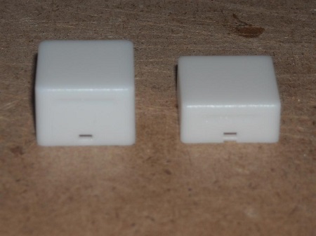
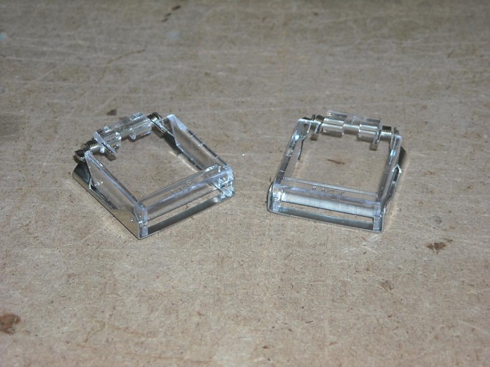
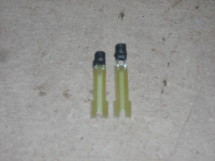
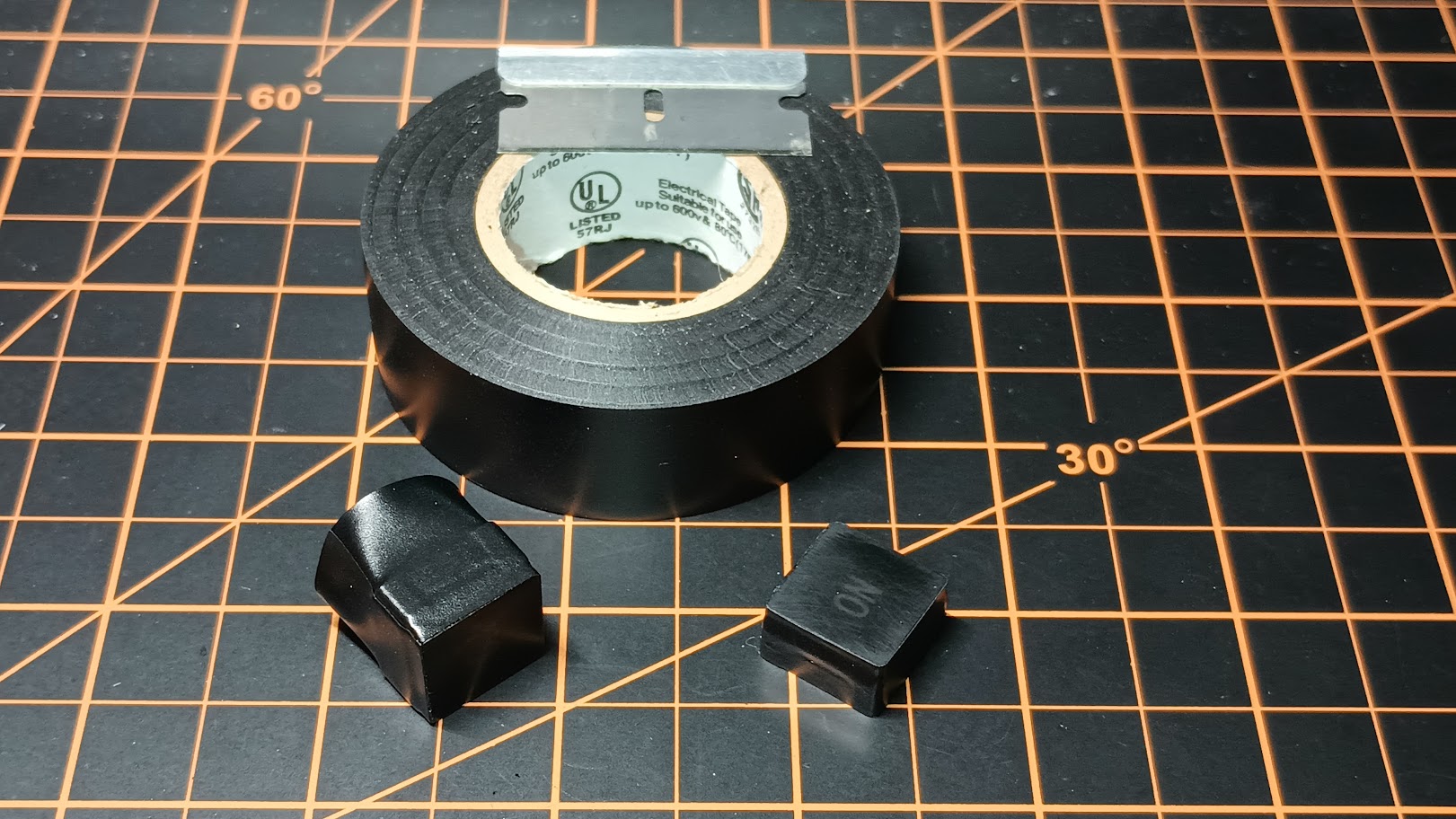
Uploaded files: (Posted by Ron Rollo on 11-14-11) Don't forget that although there are 12 guarded switches, there are four different styles. One style or size will not fit all without some mod. (Posted by Shane Barnes on 11-14-11) Yep, you order 12 of the switch guards (AML76C10T01P) which will be the "base model". They all mount to the AML switch the same way so no problems there they just slide right on to the bezel of the switch. The four differing styles that Ron mentions are detailed at the beginning of this thread. A little grinding with a Dremel tool, will give you the four differing styles of the guard located in the Lear. Then don't forget that each of the four guard styles has a unique paint scheme which is also detailed at the beginning of this thread (Posted by Alan Norris on 11-19-11) Guys, I just assembled an AML with the AML cap and switch guard and with the button in the UP (or OFF) position -- it's a latching AML, the cover will not close. What's the issue here? I know we have to modify some of the guards to get them to match the real Lear but that wouldn't seem to help this issue. (Posted by Shane Barnes on 11-19-11) Hey Alan, Iif you are using the switch cap that Ron designed it will not work with the switch guards as they are too big and were not designed to work with an off the shelf switch guard for the AML switches. This is not a design flaw in Ron's switch caps as they are very close if not the correct size of the real lear switch. We have not been able to find a source for the real switch guard for the Lear and that is why I posted this tutorial. We can use an off the shelf switch guard but we have to use another switch cap for the AML so it will fit under the guard. Email or call Eric T. and he can make you the switch caps that will work with the guards. (Posted by Ron Rollo on 10-07-13) First I want to thank Shane and Eric for their hard work on the switch guards a few years back. Lots of great ideas here! I thought I would tag onto this thread and keep all the switch guard information in one place. Lately, I have been tasked to assemble a complete set of panels including all of the hardware, wiring and wiring harnesses. This also included the switch guards which I do not even have in my sim. My plan was to try to make something from scratch so that we could still use the lens and frame pieces so that every switches looks identical. I decided to scratch that idea and just go forward with these switch guards Shane and Eric found but put my own twist on them. (After much thought in both methods, each direction has pros and cons. I am posting this information just to give everyone some ideas on their own builds.) First I suppose I need to recap some of the issues Shane and Eric ran into with these switch guards. We can not use our AML51-A10W caps because they are too tall to fit under the guards. This is why Shane went with a short cap with the white insert. The problem there is that you could not use the lens and frame kit and you have to have the cap painted and engraved. A few weeks ago Terry ordered and had sent to me a bag full of AML caps, but it turned out they were the shorter version, AML51-C10W. These were way too short for the vast majority of our AML switches, BUT, the more I looked at them and the switch guard issue, I was able to determine that they could be used while at the same time using the lens and frame kit that was already cut for these switches. Here is the thing, there are only 12 guarded switches and of those, 10 will never be used in normal flying conditions. Only the two engine START switches will be depressed at least once per flight. The method that I am going to describe in the next few post only has one minor draw back and that is each of the 12 switches are going to have to be momentary switches because they will not be allowed to be depressed fully into the AML switch to the point that you can either latch them or feel the tactical feel of the "click". However, it depresses deep enough into the AML switch that it makes it's connection to tell the sim that you just did something. Again, 10 of the 12 are nothing more than eye candy. Only the two engine START switches will be depressed twice per flight. AND, you might notice in at least FSX that when you depress these engine start switches, it makes a double clicking sound for us. Oh yeah, you don't necessarily need momentary switches, latching will work as well. They just won't get pressed deep enough to latch! Let's get on with the supplemental tutorial! Here is a photo of an AML51-A10W (TALL) next to an AML51-C10W (short). I wanted to show you the difference between the height of the two:
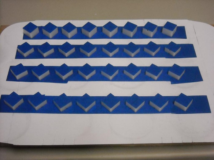
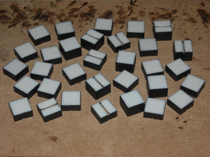
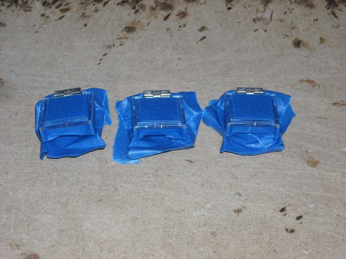
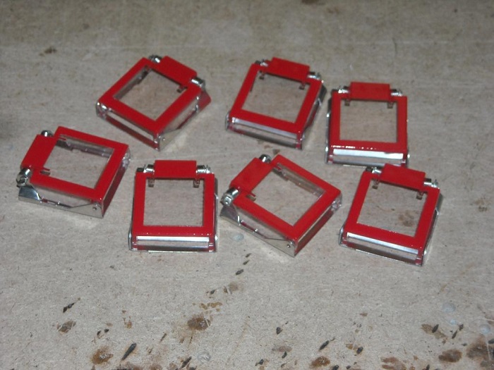
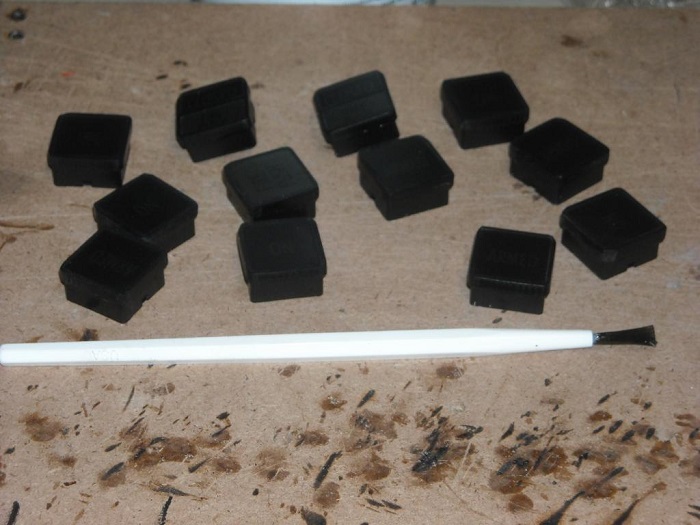
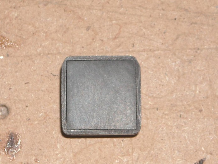
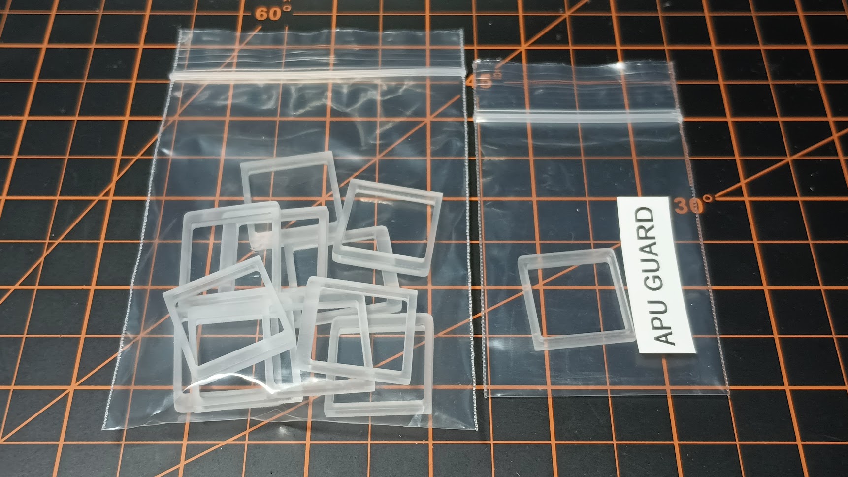
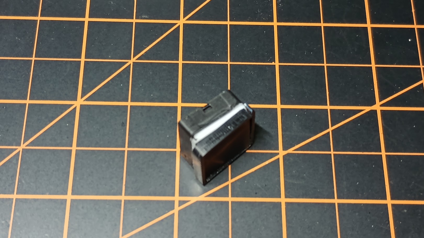
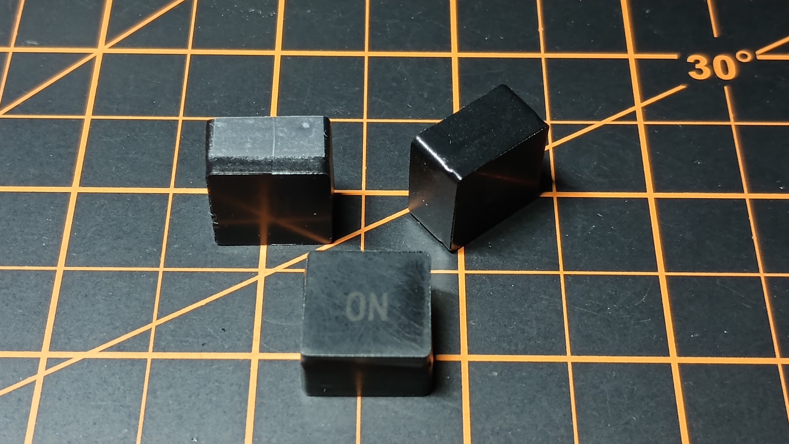
You will need to have two of the shorter caps cut in half which I will do for you for free if you send them to me. (So now you will need 10 tall caps and two short caps cut in half to make a set.) Using blue painters tape, I tape the top and use an Exacto knife to cut the excess tape off of them. Here are several of them taped down and ready for paint: NOTE: This is not a complete set, I am working on two sets and the same time. After paint and tape removed: Please remember that only 10 get painted. The two engine START switch guards are left unpainted.Here is a photo of our unpainted switch guard: Shane did a great job showing us how to make them look as close to the Lear45 switch guards as possible so I won't spend any time on that: Here is a set of seven after carefully taping them off, painting them and removing the tape. Set the guards aside for now until we get a few other things squared away. One thing that you may or may not need to do depending on what you initially did is make the LED MODS shorter. LEDs are tricky and everyone will tell you not to bend the leads too close to the LED base or you may damage it to the point that it will not work. Therefore, if your like me, you bent the leads at the point where it looks like they are made to bend which is about .1875" from the base of the LED. Here is a photo of the short LED that I had to make for these 12 guarded switches next to one of my standard length LED MODs: If your wondering, I use shrink wrap to block the light from escaping sideways. This are what I call "directional" LED MODs. And here is a photo of two of the LED MODs in the ARMED switches: They have to be this deep in order to keeping the underside of the short caps from crashing into the top of the LED. In your lens and frame kit, we have the light dividers for the double LED switches. We have two guarded switches that are double LED and we have to modify the light divider. Thankfully they are made of soft plastic and can easily be fabricated to fit into the shorter caps: Believe it or not, the shorter cap is .006" wider in both X and Y than our standard taller cap. This requires a little work with the file to get it down to the right size that the frame will fit on them: This takes just a few seconds to take a little material off of all four side so that the frame will sit on it as prescribed. A minor pain but as I have always said, nothing is that easy. (Posted by Eric Tomlin on 10-08-13) Nice tutorial. However, I see this as a trade for something that works correctly in the physical sense for something that looks a little better in the visual sense. The main thing here is like you said, you don't use the other guarded switches hardly ever, so you do not even notice in the course of a normal sim session that they are slightly different because they are covered by the pretty red guard to begin with. Also, anyone taking this method on should remember to not push the switch all the way down or you may damage something. This is now especially true for visitors to your sim who will not know, or will be prone to forget and will push your Engine Start Switches like any other switch and possibly damage the frame of the 389 lens kit. Hopefully no one will get this method confused with Shane's work that he already put ahead of this as the original topic. (Posted by Ron Rollo on 11-14-11) Don't forget that although there are 12 guarded switches, there are four different styles. One style or size will not fit all without some mod. (Posted by Shane Barnes on 11-14-11) Yep, you order 12 of the switch guards (AML76C10T01P) which will be the "base model". They all mount to the AML switch the same way so no problems there they just slide right on to the bezel of the switch. The four differing styles that Ron mentions are detailed at the beginning of this thread. A little grinding with a Dremel tool, will give you the four differing styles of the guard located in the Lear. Then don't forget that each of the four guard styles has a unique paint scheme which is also detailed at the beginning of this thread (Posted by Alan Norris on 11-19-11) Guys, I just assembled an AML with the AML cap and switch guard and with the button in the UP (or OFF) position -- it's a latching AML, the cover will not close. What's the issue here? I know we have to modify some of the guards to get them to match the real Lear but that wouldn't seem to help this issue. (Posted by Shane Barnes on 11-19-11) Hey Alan, Iif you are using the switch cap that Ron designed it will not work with the switch guards as they are too big and were not designed to work with an off the shelf switch guard for the AML switches. This is not a design flaw in Ron's switch caps as they are very close if not the correct size of the real lear switch. We have not been able to find a source for the real switch guard for the Lear and that is why I posted this tutorial. We can use an off the shelf switch guard but we have to use another switch cap for the AML so it will fit under the guard. Email or call Eric T. and he can make you the switch caps that will work with the guards. (Posted by Ron Rollo on 10-07-13) First I want to thank Shane and Eric for their hard work on the switch guards a few years back. Lots of great ideas here! I thought I would tag onto this thread and keep all the switch guard information in one place. Lately, I have been tasked to assemble a complete set of panels including all of the hardware, wiring and wiring harnesses. This also included the switch guards which I do not even have in my sim. My plan was to try to make something from scratch so that we could still use the lens and frame pieces so that every switches looks identical. I decided to scratch that idea and just go forward with these switch guards Shane and Eric found but put my own twist on them. (After much thought in both methods, each direction has pros and cons. I am posting this information just to give everyone some ideas on their own builds.) First I suppose I need to recap some of the issues Shane and Eric ran into with these switch guards. We can not use our AML51-A10W caps because they are too tall to fit under the guards. This is why Shane went with a short cap with the white insert. The problem there is that you could not use the lens and frame kit and you have to have the cap painted and engraved. A few weeks ago Terry ordered and had sent to me a bag full of AML caps, but it turned out they were the shorter version, AML51-C10W. These were way too short for the vast majority of our AML switches, BUT, the more I looked at them and the switch guard issue, I was able to determine that they could be used while at the same time using the lens and frame kit that was already cut for these switches. Here is the thing, there are only 12 guarded switches and of those, 10 will never be used in normal flying conditions. Only the two engine START switches will be depressed at least once per flight. The method that I am going to describe in the next few post only has one minor draw back and that is each of the 12 switches are going to have to be momentary switches because they will not be allowed to be depressed fully into the AML switch to the point that you can either latch them or feel the tactical feel of the "click". However, it depresses deep enough into the AML switch that it makes it's connection to tell the sim that you just did something. Again, 10 of the 12 are nothing more than eye candy. Only the two engine START switches will be depressed twice per flight. AND, you might notice in at least FSX that when you depress these engine start switches, it makes a double clicking sound for us. Oh yeah, you don't necessarily need momentary switches, latching will work as well. They just won't get pressed deep enough to latch! Let's get on with the supplemental tutorial! Here is a photo of an AML51-A10W (TALL) next to an AML51-C10W (short). I wanted to show you the difference between the height of the two:
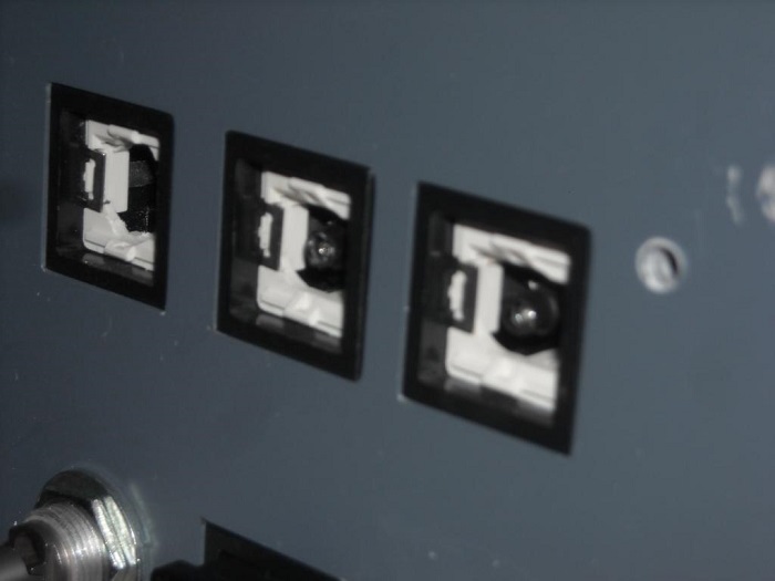
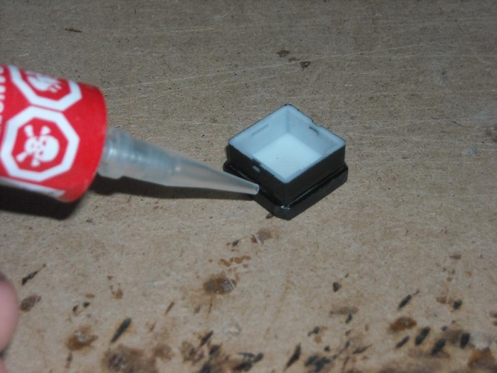
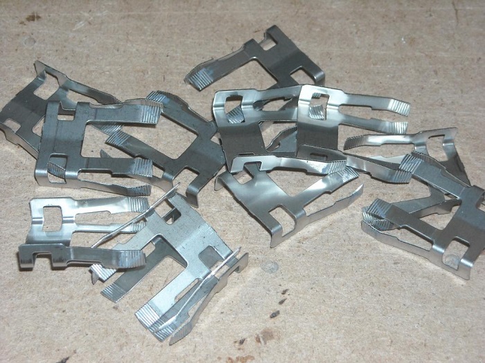
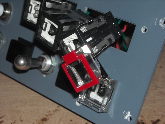
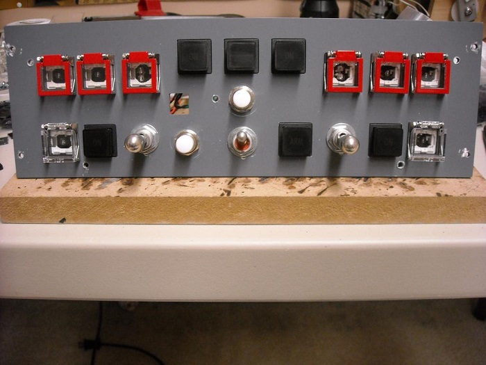
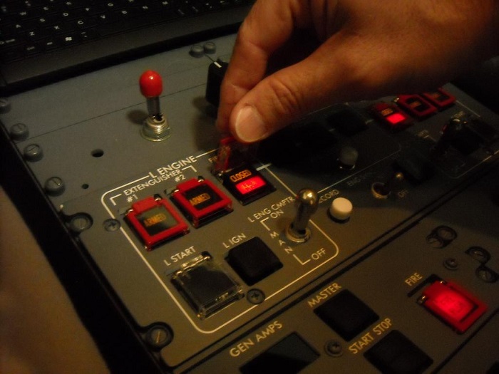
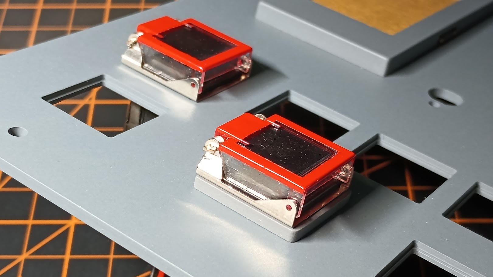
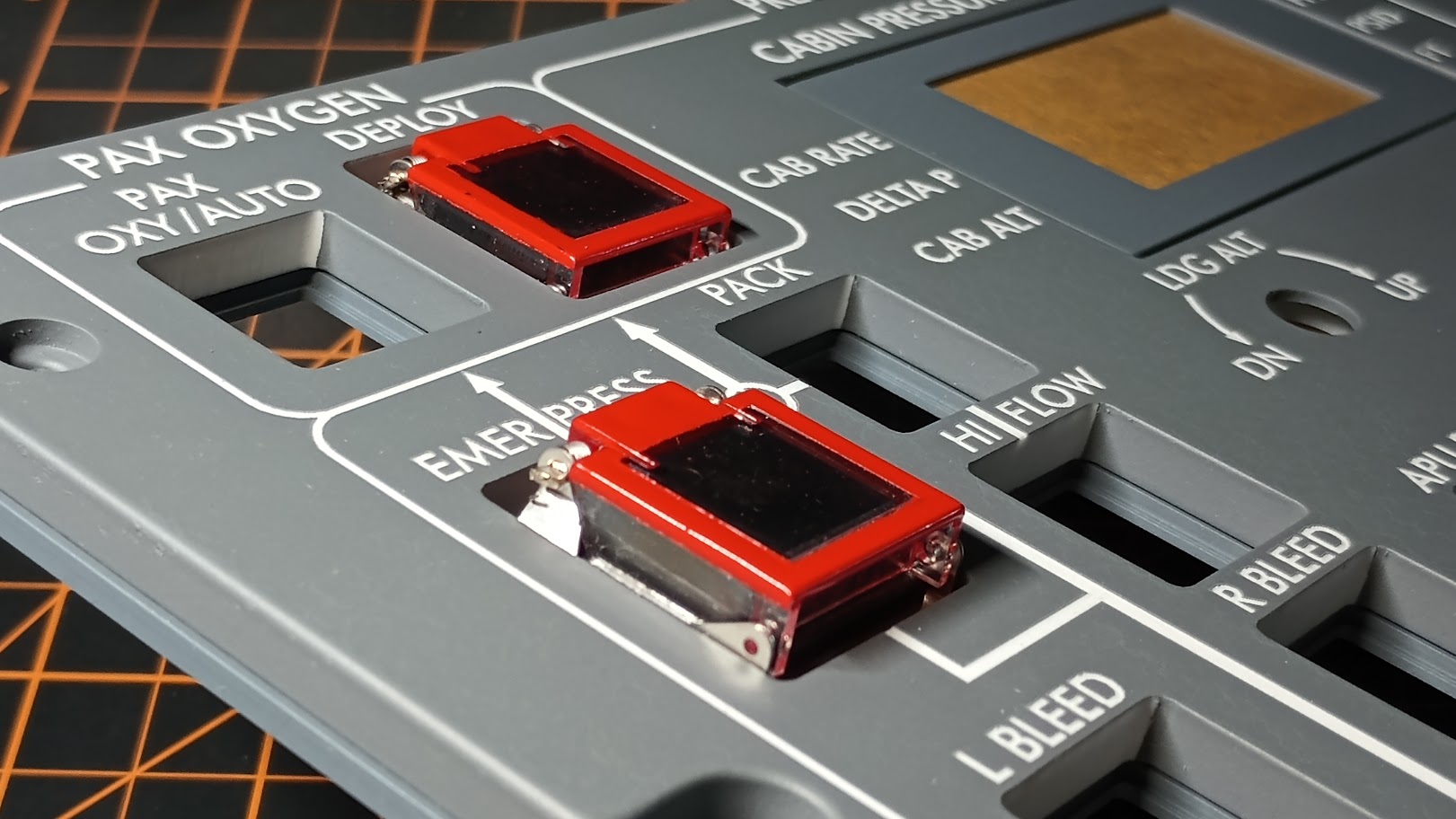
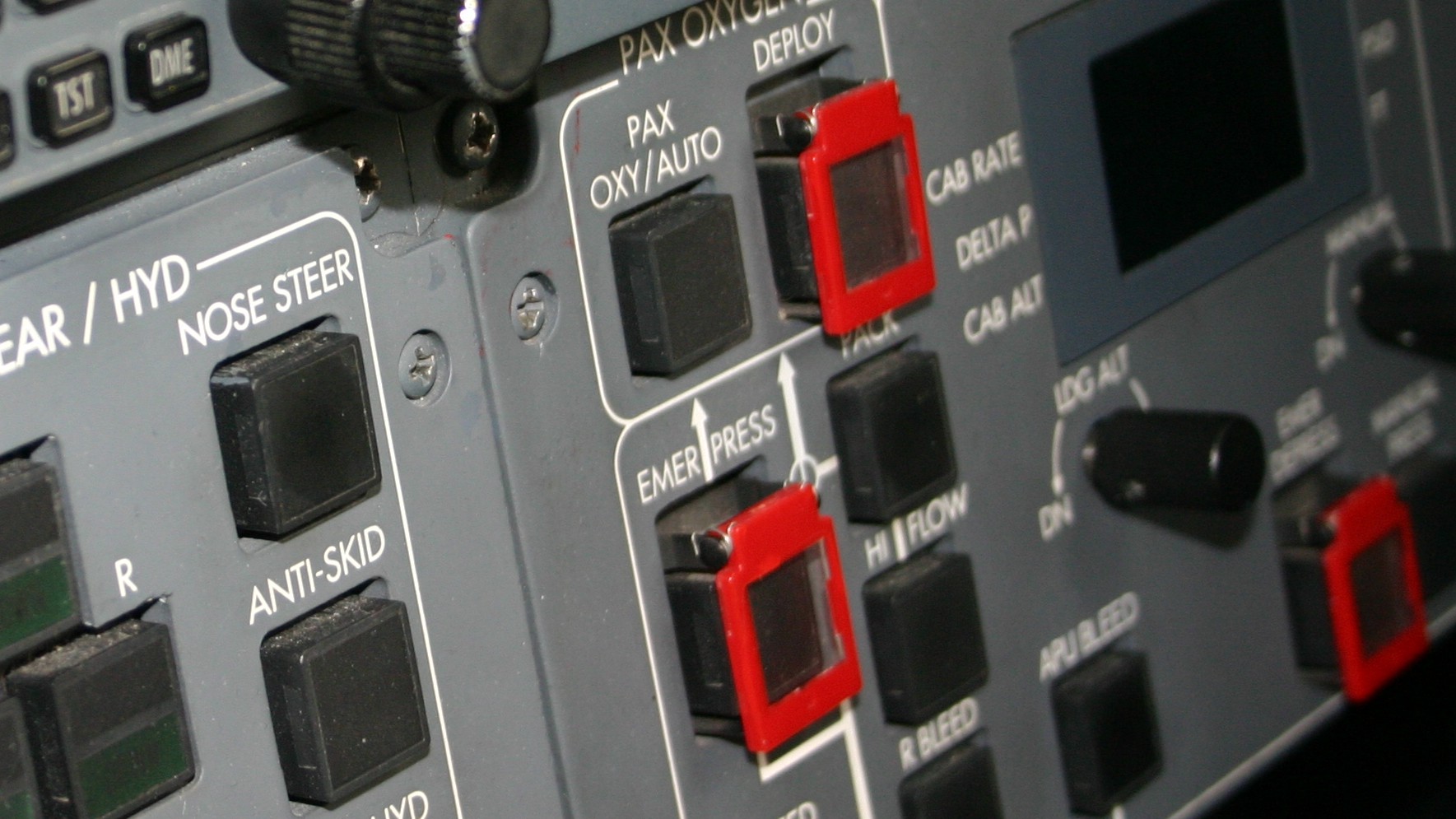
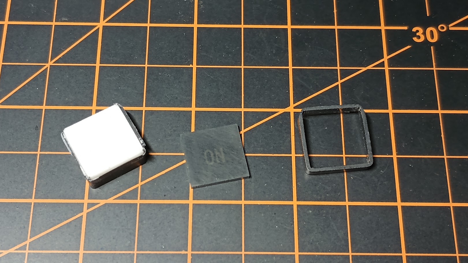
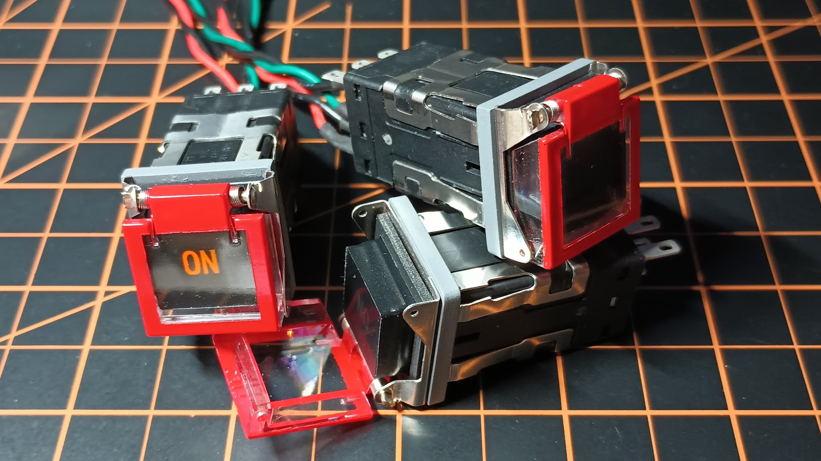
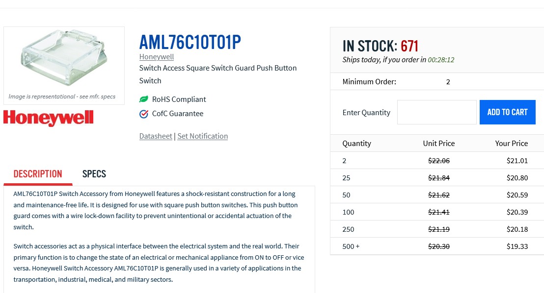
You will need to have two of the shorter caps cut in half which I will do for you for free if you send them to me. (So now you will need 10 tall caps and two short caps cut in half to make a set.) Using blue painters tape, I tape the top and use an Exacto knife to cut the excess tape off of them. Here are several of them taped down and ready for paint: NOTE: This is not a complete set, I am working on two sets and the same time. After paint and tape removed: Please remember that only 10 get painted. The two engine START switch guards are left unpainted.Here is a photo of our unpainted switch guard: Shane did a great job showing us how to make them look as close to the Lear45 switch guards as possible so I won't spend any time on that: Here is a set of seven after carefully taping them off, painting them and removing the tape. Set the guards aside for now until we get a few other things squared away. One thing that you may or may not need to do depending on what you initially did is make the LED MODS shorter. LEDs are tricky and everyone will tell you not to bend the leads too close to the LED base or you may damage it to the point that it will not work. Therefore, if your like me, you bent the leads at the point where it looks like they are made to bend which is about .1875" from the base of the LED. Here is a photo of the short LED that I had to make for these 12 guarded switches next to one of my standard length LED MODs: If your wondering, I use shrink wrap to block the light from escaping sideways. This are what I call "directional" LED MODs. And here is a photo of two of the LED MODs in the ARMED switches: They have to be this deep in order to keeping the underside of the short caps from crashing into the top of the LED. In your lens and frame kit, we have the light dividers for the double LED switches. We have two guarded switches that are double LED and we have to modify the light divider. Thankfully they are made of soft plastic and can easily be fabricated to fit into the shorter caps: Believe it or not, the shorter cap is .006" wider in both X and Y than our standard taller cap. This requires a little work with the file to get it down to the right size that the frame will fit on them: This takes just a few seconds to take a little material off of all four side so that the frame will sit on it as prescribed. A minor pain but as I have always said, nothing is that easy. (Posted by Eric Tomlin on 10-08-13) Nice tutorial. However, I see this as a trade for something that works correctly in the physical sense for something that looks a little better in the visual sense. The main thing here is like you said, you don't use the other guarded switches hardly ever, so you do not even notice in the course of a normal sim session that they are slightly different because they are covered by the pretty red guard to begin with. Also, anyone taking this method on should remember to not push the switch all the way down or you may damage something. This is now especially true for visitors to your sim who will not know, or will be prone to forget and will push your Engine Start Switches like any other switch and possibly damage the frame of the 389 lens kit. Hopefully no one will get this method confused with Shane's work that he already put ahead of this as the original topic. (Posted by Ron Rollo on 10-09-13) Hey Eric T., all of the caps are glued and will not come apart unless your trying to push your finger through the AML switch. The method I am explaining here is designed so that the builder can do all the work himself without having to have anything else sent out and engraved. Per Shane: "I started this thread due to this solution for the "switch guards" being simple, cheap and something the builder could do at home . . similar to what Ron does with a lot of his parts as it comes as a kit and allows the builder to put it together, have the fun of building it and saves money. In this case you can buy the guard directly from the supplier very cheaply and spend a couple nights modifying and painting the guard . . the smoked cap parts are a different story as they need some engraving/painting and as I stated earlier Eric can get this done for you. Contact him for pricing as I am not sure what it is." As for getting the two methods confused, I don't think that will be a problem either. The first method using the smoked caps, inserts and needing to have them shipped out and engraved is only briefly talked about and there are no illustrations showing this method. (unless I am missing something) Anyway, here is the conclusion of the modified switch guards..... At this point I am ready to glue the frames onto the caps. For me, this is nothing new because every frame is glued onto every cap to ensure they will never accidentally pop off. Simply run a bead of plastic model glue along all four sides of the underside of the frame: Then after the glue sets, I painted the sides of the caps one more time to unsure that no light will escape from them: In order to put the switch guards onto the AML switches, I have to remove my switches from the panels. The easiest way to do this is to remove the two metal clips on both sides of the AML switches with a fine point tool: And finally the fun part and the easiest part of all, sliding the guards onto the AML switches. You will feel when they click into place: Here is a photo of the engine start panel ready to get the caps installed: I found that I had to shave the two top corners on some of the frames, therefore, I shaved the top corners on all of the frames. This will insure they will not catch on the guard frame: Because the frames are glued onto the top of the caps, you can not just snap them on like you can with the tall caps. With the shorter caps, you have to hold the carriage from traveling inside the AML switch. You can hold the carriage by using a point in this spot pictured below: While holding the carriage from moving, press the cap assembly into the AML switch until you hear it click into place. At this point, I am pretty much done. Before I put everything back into the sim, I double checked that all of my LEDs and switch connections were working: Here is the engine start panel and APU panel with the new switch guards installed: Another neat photo. One thing that I noticed is that the guards are just a little hard to get a finger under them: This is a minor issue that you will encounter no matter which method you use. I'm only pointing this out in case you notice the same thing and wonder about it: All and all, I am very happy with this method and the out come of the guards. It sure beats designing something new from scratch! (Posted by Shane Barnes on 10-09-13) Nice tutorial Ron on how to finish up the guard/switch/switch cap combo. This will help you builders still needing to add the small details to your project and the small details really add to the sim! One pointer for guys going this route, watch eBay for your guards. I have seen the guards on eBay numerous times over the last two years priced quite a bit cheaper than what you will find online. Of course if you can't wait they are readily available online, happens to me from time to time! (Posted by Ron Rollo on 10-09-13) Thanks Shane! I just spent today working on a second complete set. This set went a lot faster being that I knew the path I was taking. As for the guards, I got mine from Online Components for around $9 each. Digit Key also has them at the lowest price that I could find but they were not in stock. Mouser has them also but they were almost twice as expensive as Digit Key. eBay has none listed ATM, FYI. (Posted by Ron Rollo on 10-24-16) UPDATE: It just occurred to me that I have flown the sim hundreds of times over the past few years and have had dozens of visitors in the sim flying it. Neither myself nor anyone else has ever lifted a finger to lift a RED guard to push a button under it. The AML switches under the guards are operational but just never get messed with! (Posted by Ron Rollo on 10-09-13) Hey Eric T., all of the caps are glued and will not come apart unless your trying to push your finger through the AML switch. The method I am explaining here is designed so that the builder can do all the work himself without having to have anything else sent out and engraved. Per Shane: "I started this thread due to this solution for the "switch guards" being simple, cheap and something the builder could do at home . . similar to what Ron does with a lot of his parts as it comes as a kit and allows the builder to put it together, have the fun of building it and saves money. In this case you can buy the guard directly from the supplier very cheaply and spend a couple nights modifying and painting the guard . . the smoked cap parts are a different story as they need some engraving/painting and as I stated earlier Eric can get this done for you. Contact him for pricing as I am not sure what it is." As for getting the two methods confused, I don't think that will be a problem either. The first method using the smoked caps, inserts and needing to have them shipped out and engraved is only briefly talked about and there are no illustrations showing this method. (unless I am missing something) Anyway, here is the conclusion of the modified switch guards..... At this point I am ready to glue the frames onto the caps. For me, this is nothing new because every frame is glued onto every cap to ensure they will never accidentally pop off. Simply run a bead of plastic model glue along all four sides of the underside of the frame: Then after the glue sets, I painted the sides of the caps one more time to unsure that no light will escape from them: In order to put the switch guards onto the AML switches, I have to remove my switches from the panels. The easiest way to do this is to remove the two metal clips on both sides of the AML switches with a fine point tool: And finally the fun part and the easiest part of all, sliding the guards onto the AML switches. You will feel when they click into place: Here is a photo of the engine start panel ready to get the caps installed: I found that I had to shave the two top corners on some of the frames, therefore, I shaved the top corners on all of the frames. This will insure they will not catch on the guard frame: Because the frames are glued onto the top of the caps, you can not just snap them on like you can with the tall caps. With the shorter caps, you have to hold the carriage from traveling inside the AML switch. You can hold the carriage by using a point in this spot pictured below: While holding the carriage from moving, press the cap assembly into the AML switch until you hear it click into place. At this point, I am pretty much done. Before I put everything back into the sim, I double checked that all of my LEDs and switch connections were working: Here is the engine start panel and APU panel with the new switch guards installed: Another neat photo. One thing that I noticed is that the guards are just a little hard to get a finger under them: This is a minor issue that you will encounter no matter which method you use. I'm only pointing this out in case you notice the same thing and wonder about it: All and all, I am very happy with this method and the out come of the guards. It sure beats designing something new from scratch! (Posted by Shane Barnes on 10-09-13) Nice tutorial Ron on how to finish up the guard/switch/switch cap combo. This will help you builders still needing to add the small details to your project and the small details really add to the sim! One pointer for guys going this route, watch eBay for your guards. I have seen the guards on eBay numerous times over the last two years priced quite a bit cheaper than what you will find online. Of course if you can't wait they are readily available online, happens to me from time to time! (Posted by Ron Rollo on 10-09-13) Thanks Shane! I just spent today working on a second complete set. This set went a lot faster being that I knew the path I was taking. As for the guards, I got mine from Online Components for around $9 each. Digit Key also has them at the lowest price that I could find but they were not in stock. Mouser has them also but they were almost twice as expensive as Digit Key. eBay has none listed ATM, FYI. (Posted by Ron Rollo on 10-24-16) UPDATE: It just occurred to me that I have flown the sim hundreds of times over the past few years and have had dozens of visitors in the sim flying it. Neither myself nor anyone else has ever lifted a finger to lift a RED guard to push a button under it. The AML switches under the guards are operational but just never get messed with! Tired of your flights going to hell because you can't put that pesky engine fire out in a timely manor? Or passing out due to oxygen deprivation because you can't get your finger under any of the Pressurization switch Guards? Then you need................HELL RISERS! Hell Risers lift your guarded switches up out of the panels so that you can easily lift the guards with your finger when you are dealing with a life threatening emergency! No more fumbling with switch guards or wishing you had longer finger nails, a complete set of Hell Risers fix this for just $19.95! A set of Hell Risers address all the guarded switches on the Engine and Pressurization Panel. If you act now, we will also include the APU Hell Riser for free, just pay additional shipping and handling! All kidding aside, I am in the process of rewiring all my panels and have been putting off the Pressurization and Engine panels until now because of the Guarded Switches. This photo shows a couple guarded switch on the Pressurization panel. In the foreground is a switch with a hell riser under it. The guarded switch in the background does not have the hell riser under it. This photo includes the front panel which clearly shows the benefit of having the Hell Risers installed. And this photo is of the real Pressurization panel in a Lear45! Notice how high the guarded switches are protruding out of the panel? Not only does the Hell Risers resolve the problem of not being able to get your finger under the guards to lift them, this solution also gets us a little closer to looking correct. Wondering why our guarded switches are not exactly the same as the ones in the real Lear45? We are using AML switches, caps and guards in our sims. The real Lear45 uses Chromolux 389 type switches and hardware at ten times the cost! Wondering how I come up with the name "Hell Risers"? I figured anytime you have to push a switch under any of the red guards, your flight has just gone to hell! If you would like a set of Hell Risers, just send an email request. If you would like to make them yourself, I can also provide the drawings and G-code. REMOVING FRAME LENSES ON GUARDED SWITCHES Another issue that has to be addressed when it comes to the guarded switches is the lens frames need to be removed so that the switches can be pushed all the way into the AML switch body allowing it to latch or click, if momentary. I have to give credit to Jason for pioneering this effort and being the first to be brave enough to make the necessary modifications to these guarded switch! He did something similar to what I have outlined below but the big difference is he used custom made 3D printed short caps in place of the authentic AML51-C10W (short) caps. We have corrected several of the guarded AML switches in the Jet45 AAS Systems Modules document that were previously momentary but are in fact latching. The new v2.0 software requires all hardware work as the Jet45 AAS Systems Modules document has it listed in order for everything to preform properly. In cases like the guarded switches, if the switch is a latching switch, it MUST be able to be pressed all the way into the AML body and latch, in other words, hold the circuit closed until pressed again. The following is a quick tutorial on how to modify your guarded switches so they will be compliant with the v2.0 software. A positive side effect to this modification is you will now have the tactical "click" or latching when pressed! Here you can see the frame around the lens on top of a short cap. when pressed, the switch goes deep enough to close the contact while being held, but not deep enough to latch or click if momentary. Not good. First step is to remove the cap with lens and frame from the AML. The lens frames has to be removed from the cap. I used Testors plastic model glue originally so breaking the two pieces apart from one another was easy. Here is the cap broken apart in three pieces. Sand the extra glue off the cap and discarded the frame at the far right of the photo below. I did some research on different ways to attach the lens back to the cap using glues and tape. Each of you might have other or even better methods in mind. I will share with you my favorite method and explain why I like it and what I don't like. I opted to use electrical tape! What I like is it blocks 100% of the light, it's flexible and easy to cut. What you have to be careful about if using electrical tape is it's thick and there is not much clearance for the cap to go down into the AML body, let alone wrapped with tape. As it is, I could only wrap the cap with lens once and then put a small piece of Scotch tape along the back insuring the electrical tape does not work itself loose. The other thing that is not cool is if you have to remove the cap from the AML, plan on wrapping the cap again because it will get screwed up trying to pull it out of the AML. Here are a couple short caps for the AMLs with guards remade with the electrical tape method. Notice the small piece of Scotch tape? I am not sure the Scotch tape is necessary but better to be safe and have it than not. They don't look bad and they seem to work great! I would not go this route with all the AMLs in the build because without the frame, the switches are slightly under sized, but under the switch guards, it's not noticeable. And how often will we be lifting a guard to press one? The three guarded switches completely modified with the Hell Risers in place ready to be installed on the Pressurization panel! While I am thinking about it, I did a search for the AML51-A10W (TALL) and AML51-C10W (short) caps. They are in the process of becoming obsolete and are at "End Of Life" which means they are getting harder and harder to find and more and more expensive! The good news is Jason has come up with a way to produce 3D printed cap replicas, tall, short and even with the dividers built into them for the dual LED situations! A great solution to a couple problems we are facing! Thanks Jason! Any questions or comments welcome! Tired of your flights going to hell because you can't put that pesky engine fire out in a timely manor? Or passing out due to oxygen deprivation because you can't get your finger under any of the Pressurization switch Guards? Then you need................HELL RISERS! Hell Risers lift your guarded switches up out of the panels so that you can easily lift the guards with your finger when you are dealing with a life threatening emergency! No more fumbling with switch guards or wishing you had longer finger nails, a complete set of Hell Risers fix this for just $19.95! A set of Hell Risers address all the guarded switches on the Engine and Pressurization Panel. If you act now, we will also include the APU Hell Riser for free, just pay additional shipping and handling! All kidding aside, I am in the process of rewiring all my panels and have been putting off the Pressurization and Engine panels until now because of the Guarded Switches. This photo shows a couple guarded switch on the Pressurization panel. In the foreground is a switch with a hell riser under it. The guarded switch in the background does not have the hell riser under it. This photo includes the front panel which clearly shows the benefit of having the Hell Risers installed. And this photo is of the real Pressurization panel in a Lear45! Notice how high the guarded switches are protruding out of the panel? Not only does the Hell Risers resolve the problem of not being able to get your finger under the guards to lift them, this solution also gets us a little closer to looking correct. Wondering why our guarded switches are not exactly the same as the ones in the real Lear45? We are using AML switches, caps and guards in our sims. The real Lear45 uses Chromolux 389 type switches and hardware at ten times the cost! Wondering how I come up with the name "Hell Risers"? I figured anytime you have to push a switch under any of the red guards, your flight has just gone to hell! If you would like a set of Hell Risers, just send an email request. If you would like to make them yourself, I can also provide the drawings and G-code. REMOVING FRAME LENSES ON GUARDED SWITCHES Another issue that has to be addressed when it comes to the guarded switches is the lens frames need to be removed so that the switches can be pushed all the way into the AML switch body allowing it to latch or click, if momentary. I have to give credit to Jason for pioneering this effort and being the first to be brave enough to make the necessary modifications to these guarded switch! He did something similar to what I have outlined below but the big difference is he used custom made 3D printed short caps in place of the authentic AML51-C10W (short) caps. We have corrected several of the guarded AML switches in the Jet45 AAS Systems Modules document that were previously momentary but are in fact latching. The new v2.0 software requires all hardware work as the Jet45 AAS Systems Modules document has it listed in order for everything to preform properly. In cases like the guarded switches, if the switch is a latching switch, it MUST be able to be pressed all the way into the AML body and latch, in other words, hold the circuit closed until pressed again. The following is a quick tutorial on how to modify your guarded switches so they will be compliant with the v2.0 software. A positive side effect to this modification is you will now have the tactical "click" or latching when pressed! Here you can see the frame around the lens on top of a short cap. when pressed, the switch goes deep enough to close the contact while being held, but not deep enough to latch or click if momentary. Not good. First step is to remove the cap with lens and frame from the AML. The lens frames has to be removed from the cap. I used Testors plastic model glue originally so breaking the two pieces apart from one another was easy. Here is the cap broken apart in three pieces. Sand the extra glue off the cap and discarded the frame at the far right of the photo below. I did some research on different ways to attach the lens back to the cap using glues and tape. Each of you might have other or even better methods in mind. I will share with you my favorite method and explain why I like it and what I don't like. I opted to use electrical tape! What I like is it blocks 100% of the light, it's flexible and easy to cut. What you have to be careful about if using electrical tape is it's thick and there is not much clearance for the cap to go down into the AML body, let alone wrapped with tape. As it is, I could only wrap the cap with lens once and then put a small piece of Scotch tape along the back insuring the electrical tape does not work itself loose. The other thing that is not cool is if you have to remove the cap from the AML, plan on wrapping the cap again because it will get screwed up trying to pull it out of the AML. Here are a couple short caps for the AMLs with guards remade with the electrical tape method. Notice the small piece of Scotch tape? I am not sure the Scotch tape is necessary but better to be safe and have it than not. They don't look bad and they seem to work great! I would not go this route with all the AMLs in the build because without the frame, the switches are slightly under sized, but under the switch guards, it's not noticeable. And how often will we be lifting a guard to press one? The three guarded switches completely modified with the Hell Risers in place ready to be installed on the Pressurization panel! While I am thinking about it, I did a search for the AML51-A10W (TALL) and AML51-C10W (short) caps. They are in the process of becoming obsolete and are at "End Of Life" which means they are getting harder and harder to find and more and more expensive! The good news is Jason has come up with a way to produce 3D printed cap replicas, tall, short and even with the dividers built into them for the dual LED situations! A great solution to a couple problems we are facing! Thanks Jason! Any questions or comments welcome! And here I was thinking its my delicate little fingers (No they are not at all fat, who said that!!) that were the problem. Thank you for pointing out and solving this, it will make any double engine fire with cabin decompression emergency far more convenient and almost a pleasure - at least once! Given that you cant move the spring steel retaining clips and this mod moves the body with the clip up - is there enough clip to firmly hold these AML’s in place? And here I was thinking its my delicate little fingers (No they are not at all fat, who said that!!) that were the problem. Thank you for pointing out and solving this, it will make any double engine fire with cabin decompression emergency far more convenient and almost a pleasure - at least once! Given that you cant move the spring steel retaining clips and this mod moves the body with the clip up - is there enough clip to firmly hold these AML’s in place? Hey Will, I think a couple of us were wondering the same thing and I never put a lot of thought into it until now while getting ready to wire up the Engine and Pressurization panels. Back in the day we were all in a rush to get our sims up and running no matter the condition so a lot of the little things like this went unchecked. While talking to Shane about this new solution I came up with, I was surprised to hear that he already had switch guard risers under his guarded switches. But his are "C" shaped making it easy to slide onto the switch if you already have the switches wired. Turns out Eric Tomlin made these for Shane and himself but I am not aware if anyone else has them because I was not aware anyone had them! LOL If you have not yet rebuilt your Engine and Pressurization panels, the Hell Risers will slip up from the bottom of the AML to the underside of the top lip with hardly no issues. Some are tight but they will still slide up and into place. The only one I had an issue with was the APU Hell Riser. I made it so that it was only half the height of the others but it also has a lip that fits into the AML notch. The results are the APU guarded switch sits a tiny bit lower than the other guarded switches (like you see in the real Lear45) If you already have your switches wired up, you could remove the top part with a pair of wire snipers so that the Riser can easily be slip around the wires and into place. You can also remove the metal spring retaining clips to make installation easier. They come off super easy, here is a stack of them. Just takes a screw driver and a little pry pressure and they pop right off. They pop back on just as easy. As a matter of fact, if you have to remove the AMLs from the Electrical backer panel, this is the best way to do it because the switches are so bunched up and on top of each other. As for the way the AMLs fit in the panels with the Hell Risers? Because of the extra material, it pushes the switch up and out of the backer panel a little further. But they are still very much firmly seated and will not come loose, even during high negative G situations! Hey Will, I think a couple of us were wondering the same thing and I never put a lot of thought into it until now while getting ready to wire up the Engine and Pressurization panels. Back in the day we were all in a rush to get our sims up and running no matter the condition so a lot of the little things like this went unchecked. While talking to Shane about this new solution I came up with, I was surprised to hear that he already had switch guard risers under his guarded switches. But his are "C" shaped making it easy to slide onto the switch if you already have the switches wired. Turns out Eric Tomlin made these for Shane and himself but I am not aware if anyone else has them because I was not aware anyone had them! LOL If you have not yet rebuilt your Engine and Pressurization panels, the Hell Risers will slip up from the bottom of the AML to the underside of the top lip with hardly no issues. Some are tight but they will still slide up and into place. The only one I had an issue with was the APU Hell Riser. I made it so that it was only half the height of the others but it also has a lip that fits into the AML notch. The results are the APU guarded switch sits a tiny bit lower than the other guarded switches (like you see in the real Lear45) If you already have your switches wired up, you could remove the top part with a pair of wire snipers so that the Riser can easily be slip around the wires and into place. You can also remove the metal spring retaining clips to make installation easier. They come off super easy, here is a stack of them. Just takes a screw driver and a little pry pressure and they pop right off. They pop back on just as easy. As a matter of fact, if you have to remove the AMLs from the Electrical backer panel, this is the best way to do it because the switches are so bunched up and on top of each other. As for the way the AMLs fit in the panels with the Hell Risers? Because of the extra material, it pushes the switch up and out of the backer panel a little further. But they are still very much firmly seated and will not come loose, even during high negative G situations! I still haven't found where to buy the guards (for a reasonable price) But if anybody know where to get the originals ?? I still haven't found where to buy the guards (for a reasonable price) But if anybody know where to get the originals ?? Hey Roel, The switch guards are out there but the price of them are high which you already know. The best I could find were from Online Components at $21.01 per switch guard. You can find them HERE Some places want as much as $44 per piece for them! And as I mentioned before, they are not exactly what you will find in the Lear45, but they are exactly what works perfectly with the AML20 and AML21 series switches. Hey Roel, The switch guards are out there but the price of them are high which you already know. The best I could find were from Online Components at $21.01 per switch guard. You can find them HERE Some places want as much as $44 per piece for them! And as I mentioned before, they are not exactly what you will find in the Lear45, but they are exactly what works perfectly with the AML20 and AML21 series switches.Switch Gaurds for the AML Tutorial
![]()
![]()
![]()
![]()
![]()
![]()
![]()

![]()
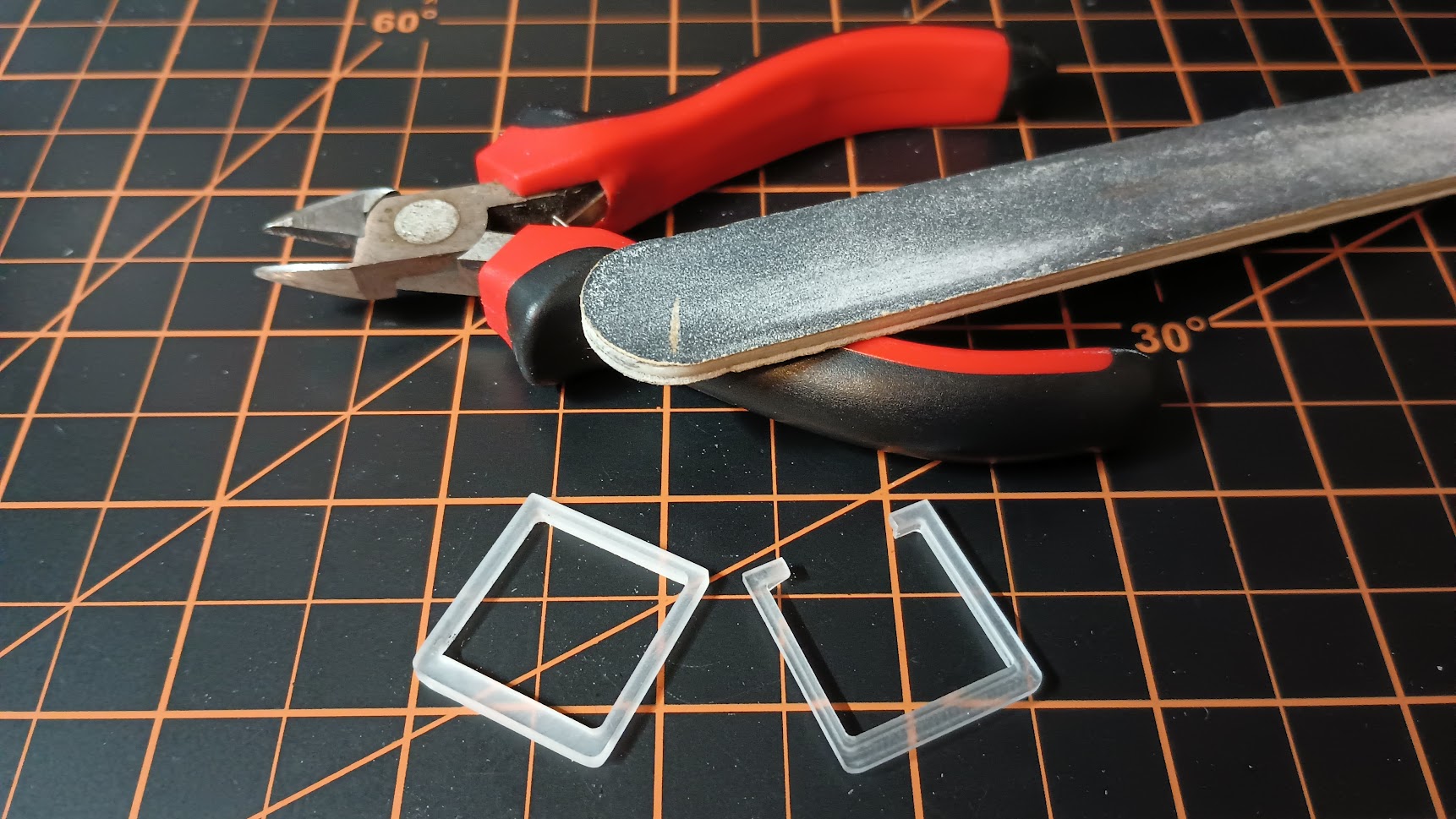
For now I have these China guards which I modify with my CNC to fit.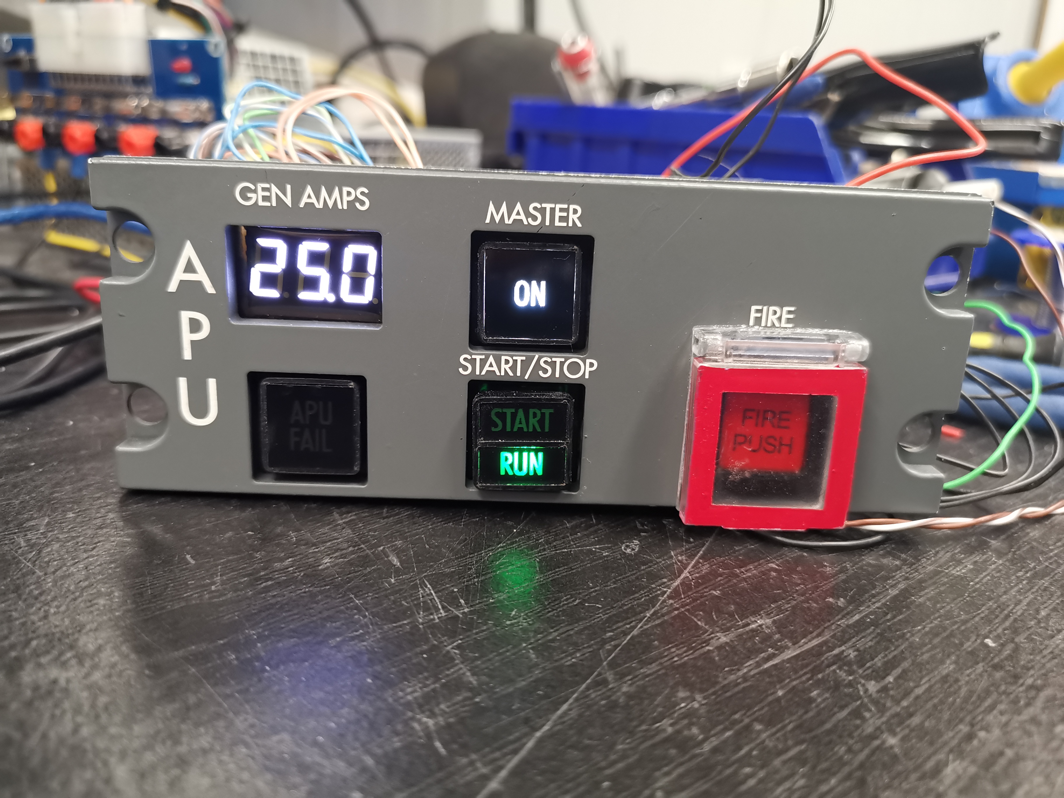
For now I have these China guards which I modify with my CNC to fit.![]()
Forum NavigationSwitch Gaurds for the AML Tutorial
![]() #1 · December 7, 2017, 9:45 am
#1 · December 7, 2017, 9:45 am![]() #2 · December 29, 2017, 9:29 pm
#2 · December 29, 2017, 9:29 pm![]() #3 · December 29, 2017, 9:37 pm
#3 · December 29, 2017, 9:37 pm![]() #4 · December 29, 2017, 10:33 pm
#4 · December 29, 2017, 10:33 pm![]() #5 · October 15, 2022, 11:20 pm
#5 · October 15, 2022, 11:20 pm![]() #6 · October 17, 2022, 4:53 am
#6 · October 17, 2022, 4:53 am![]() #7 · October 17, 2022, 7:20 am
#7 · October 17, 2022, 7:20 am![]() #8 · October 17, 2022, 1:15 pm
#8 · October 17, 2022, 1:15 pm![]() #9 · October 18, 2022, 2:06 pm
#9 · October 18, 2022, 2:06 pm
2017-10-10