


(Original thread started on 04-29-09 by Ron Rollo) L45-007 in kit form has been completed and it shipped out on this date, 04-29-09 to Shane Barnes in Mt. Sterling, Kentucky. I thought I would start a thread for his shell so everyone can follow the progress, starting in my work shop in Jacksonville Florida. Thanks Shane! Here is L45-007 crated up and ready for the road trip to Kentucky! (L45-002 is in the back ground) (Posted by Eric Tomlin on 04-30-09) Shane, welcome to the club of 'Shell Owners' my friend! It's lots of work, but well worth it in the end. Looks to me like you could wind up using the crate it's shipped in as a great sim base to build on! Ron does great work. (Posted by Shane Barnes on 04-30-09) Hey guys, thought I would share a photo of my "generic sim". This was my humble first attempt at building an enclosed sim. It was supposed to be a King Air when I first started but soon realized . . no support for King Air: Meanwhile, I've been looking over Ron's "SAM" and sounds like you are right . . a lot of work, but should be a lot of fun. I like building on the sim as much as flying. The shell is due to arrive in Kentucky Monday. I officially started on L45-007 project today, 05-01-09 at 5:15pm. I purchased the necessary materials to construct a rolling base for 007. The list of materials include (4) 2 x 6 x 8, (1) 4 x 8 sheet of 3/4in plywood, (4) rollers, (20) 3.5in long lag screws, (16) 1in long lag screws for rollers, and (36) washers for screws: About one hour later I had the 2 x 6's cut to the proper dimensions and ready to assemble. A side note, I purchased the materials at Lowe's and they cut the plywood to length for me. Just a little easier than trying to do it at home on a smaller table saw, and they didn't charge for this service: (Posted by Ron Rollo on 05-01-09) Dang Shane! That base looks perfect! You will have no problems with the column system down the road. It is a great idea to have the base ready by the time the shell arrives. You'll have L45-007 sitting pretty by Tuesday! By the way for those following along, the crate is a few inches shy cross ways meaning that some of the shell near the rear hangs off on the left and right sides. You can sort of see this in the first picture of this thread as the shell is setting on the crate. The crate can be used as a base but would need some modifications to make it work properly. (Posted by Shane Barnes on 05-02-09) I finished assembling the frame, attached the rollers and 3/4 in plywood. I also printed a copy of Ron's (SAM) shell assembly manual for reference at the garage and added the 12" square grid lines to the plywood. Now I will wait for the shell delivery scheduled for Monday: I received Ron's shell kit today and as you can see it fits nicely in the rear of a full size truck. Two persons can easily load this crate: I started uncrating 007 at the garage. As you can see, Ron does an excellent job at crating and protecting the parts from damage during shipment. I started assembly around 4:00pm: And by about 5:00pm I had one half together: 6:45pm I had both sides of the shell assembled . . still need to do the bolting but basic assembly done. As Ron mention's in the assembly manual . . it requires two people to do the assembly but as you can see goes rather quickly: I am really impressed with the fit and finish of Ron's product. There is no doubt many hours went into the planning of his shell kit and it shows. Enough work for tonight. (Posted by Ron Rollo on 05-04-09) Thanks Shane for the kind words! This is a labor of love and I enjoy building something for guys like you who truly appreciate it. Your in for the build of your life I think! All the hard work in the coming months will pay off in the end. (Posted by Shane Barnes on 05-06-09) Worked on the shell for the last two nights and I have all the bolting done and the port side lower lateral strips are notched in. The notching went smooth and I took my time with this step. I forgot the camera when I went to the garage, so I will try to remember tomorrow night to take an update photo. As of last night, I had completed shaving the shell. Tonight I plan on cutting the windscreen templates to ensure they line up right with my shaving efforts . . then disassembly . . paint . . caulk . . I gotta get back to the shell. Talk to you guys soon . . having a lot of fun! UPDATE: I finally remembered to take the camera to the garage. I have completed the shaving on 007, and have the windscreen templates cut out. I wanted to check their fit prior to disassembling the shell for paint: I was not able to find the door skins that Ron used for template material; however you can use 1/8" paneling and works just as good . . just a little more material waste. UPDATE: Started painting the shell tonight . . time consuming but nice to know that it is one step closer to final assembly. I decided to prime the pieces with a white brush on primer prior to painting with spray can. This should seal the porous areas of the MDF and use less spray paint. Will post how this turns out: One half painted, one to go! I decided to prime all the parts with a paint gun . . this made priming go faster . . I still applied the apple green by can (actually the color is Pistachio, seems apple green is hard to come by in Kentucky right now . . very close to the apple green Ron used) UPDATE: I finished installing the aluminum sheeting on 007 this evening, and started on caulking the exterior of the shell. Most likely two more nights of caulking before completing this phase if all goes well. (Posted by Ron Rollo on 05-26-09) Looking too good Shane! Make sure you caulk the aluminum in really good. When you apply the foam, you want it to expand out, away from the shell. There were a few places on my shell where it wanted to expand back into the aluminum. I freaked out when I saw what it was doing, but then the next day, the swelling went down. I also used very then aluminum flashing. If you happened to use something thicker, you'll have no issues at all. (Posted by Shane Barnes on 05-26-09) Hi Ron, I'm putting the caulk on thick so hopefully it will minimize the push back effect into the aluminum. Did you have any issues with the foam not wanting to stick to the caulk? I wouldn't think that would be an issue, but you have already been there to see if it is. I also used four pieces of flashing at the top front area as you suggested in the SAM. I didn't have any binding issues. I was also able to pop rivet the sections together as well as screwing into the poly to hold the curvatures better. I do not expect any problems associated with riveting the sections, but we will see as I progress. I've completed caulking about 90% of exterior and should be able to start on the interior in the next day or two. It is taking a little while for the caulking to set up due to the humid weather we are having. So I am letting it take its time to set up before applying interior caulk. UPDATE: Well I started growing my Chia Pet Lear Jet tonight, actually, I started applying foam to the top sections of the shell tonight. I plan on letting the foam sit overnight, then splitting the shell in two and laying the sections on their side to apply the foam to the sides . . then let it sit for several days . . that will give me time to get caught up on all the jobs around the house that I have neglected the last couple of weeks (and keep me out of trouble!) (Posted by Ron Rollo on 05-29-09) Great work Shane! Very good idea to leave it be for several days. If you do get the urge to shave the big puffy parts off, or in other words, trim the tops of the little mountains off, DON'T! I did and ended up having to go back and add more foam because I cut too much off and then it retracted. I tell you, this stuff breathes back and fourth and needs to cure fully. My wife says, "Wow, does this guy have a job? He sure is getting it done quickly." Then I explained that your a cop. Now she understands. (Posted by Shane Barnes on 05-30-09) Good thing about my job, flexible schedule! and working on the shell is good after work therapy! Gets my mind off all the crazy things that happen at work! I finished applying the foam to the second half of 007 tonight . . so now I will wait until this weekend (Sat) before I do any more work to the shell. This should give the foam time to cure: I finished the first sanding of the foam this afternoon on both sections of the shell. I will let it sit for a couple of days before I do the final sanding, just to see if the foam expands or contracts any. . . then I will start fitting the windscreen templates to the shell in preparation for adding the fiberglass. (Posted by Ron Rollo on 06-08-09) Every time I see your work Shane, I think I am looking at my own! After a few days, you will probably see that the foam has expanded or contracted a little. Obviously, Great Stuff is not FAA approved and it was never intended for this sort of application, but we must do what it takes to get the job done! (Posted by Shane Barnes on 06-08-09) Thanks guys for the encouragement! Hey Ron, do you remember foam dust? Now looking forward to fiberglass. Looking forward to more progress on 002! Guys, the shell has been a lot of work, and I have moved fairly quick with it, but having a flexible schedule and my wife having a job that requires a lot of night and weekend work gives me plenty of time to work on it. Working on the shell keeps me occupied (love this hobby). . and my wife knows where I am. I want to be able to finish the fiberglass work by mid July, and hopefully apply paint soon thereafter. I want to be able to move the shell back to my home and out of my father's garage so I don't tie up his shop to long! UPDATE: I have started the fiberglass work on 007. I have fiberglass on the top sections of the nose and above windscreens. Next step is to split the shell and lay them on their sides and apply fiberglass. I now have the major fiber glassing completed on both sections of the shell: I started the smoothing process on this section . . better known as applying Bondo. This will smooth any imperfections (mistakes)! After applying the Bondo, and working it down with a putty file to get a smoother surface, I applied a thin skim coat of Bondo to fill in any small holes or voids left by the putty file. Next step is to sand the skim coat of Bondo with the sanding board pictured in the photo below: I've smoothed the bottom section first, then I will rejoin the two shell sections and make it easier on me to smooth the top section. Not as much bending over and for me that is less backache. This part is somewhat time consuming, but really nice watching the shell take its final shape. Still a lot of work. After the skim coat of Bondo is sanded I will start with a couple rounds of primer . . then putty to fill any small pits or scratches left from sanding . . then start with primer and finer grade of sandpaper to prepare the surface for final paint. UPDATE: I have one side of the shell in final primer and ready for paint. I started last night on smoothing out the second half of the shell with Bondo. I have about four days off work starting tomorrow so I hope to finish the second half this week. Here is the first side finished in final primer. This coat of primer will be sanded with 400 grit paper prior to painting. I won't sand this final coat until the second side is at this point. I will paint the front rib (F-1) green. I done some smoothing and filling to cover the notches for the lateral strips: As for the second side, I started last night applying Bondo to smooth it out. The top portion is roughed in and the area around the windscreen is roughed in, still some more filling and smoothing in these areas, and of course smoothing the bottom section where the fiberglass is still showing: (Posted by Eric Tomlin on 07-23-09) Shane, here's a great photo regarding a question you had in reference to the interior structural color: http://www.airliners.net/photo/Learjet-40/1520940/M/ (Posted by Shane Barnes on 07-29-09) Hey guys, I would like to get your input on how to cut the plexiglass windscreens for 007. I cut both windscreen templates at the same time as they are mirror images of each other. I first taped Ron's paper template supplied with his shell kit to the 1/8in paneling. Then I drilled several holes as marked on Ron's paper template thru the paneling, inserted small bolts and nuts to hold both pieces of paneling together while cutting. I then traced the outline of the windscreens onto the paneling and cut out the windscreens using a jigsaw. This worked good for wood paneling, but I don't know how well that will work with plexiglass. This is how I plan on cutting the plexiglass . . as both windscreens are mirror images of each other, I will use one as a template . . I will lay the template on top of both pieces of Plexi . .drill holes down thru the template . . insert bolts and nuts again to keep both pieces of Plexi and the template together while cutting. I've cut thicker Plexi before using a fine toothed jigsaw blade, but have concerns how this will work with 1/8in thick Plexi, I also have available a Dremel tool with side cutting bits and a full size router. I have thought about using the Dremel with a side cutting bit and follow around the perimeter of the wood template. I figured that several of you have cut/used Plexi at some point in your projects and wanted your input before I start cutting. Might save myself from scrapping the Plexi. Tell me what you think. (Posted by Ron Rollo on 07-30-09) Hey Shane, this is something that I should have had finished by now. But too busy on other stuff! Your right in thinking that the first step is to lay the windscreen jig on top of the Plexiglas, drill and then bolt the two pieces together. If both sides are the same in your case, your right, you can save time and do both at the same time. I am going to experiment on a scrap corner and see how the Plexiglas responds to a jig saw and then try my hand held router on it. If in both cases they pass the test, I will know what to do. And that is: I am going to rough cut the bulk off with the jig saw. Then come back and hit the edge with the router. I may have to do some light sanding too. Do not try this with out a temporary windscreen to work off of! (Posted by Tom Goldberg on 07-30-09) Shane, if you use a Dremel with a fiberglass cut off wheel is probably the easiest way to cut and control your cut with out splitting the plexiglass, but like any other plastics as you cut it tends to build up heat real quick and gunk's up the edges a little bit but might work. On the other hand if you use a jigsaw it can split this stuff or crack due to the motion of the jigsaw. One trick you might try if you have some thin plywood you can waste would be to sandwich your plexiglass between 2 pieces of plywood run screws down through the perimeter of what your cutting out to hold it in place trace your windscreen on the top plywood board and then cut it out with a jigsaw. Anyway, those are my best ideas. (Posted by Shane Barnes on 07-30-09) Hi Ron and Tom, thanks for the input . . both templates are mirror images so what I might be able to do is place my Plexi between the two templates, place the bolts thru and cut, then it would be sandwiched between as you mentioned . .this would keep the Lexan perfectly aligned and give it some support as well. I can cut off the excess as Ron mentioned then go back and clean up the edges. I read somewhere that when cutting Plexi to tape the area where it will be cut to keep it from welding itself back together. I think I am going to play around with this a little this evening if all goes well, I might have a Plexi windscreen instead of wood. After a few hours of work I now have two windscreens that I think are going to work. The windscreens are hazy looking because I left the protective plastic on until final assembly: I used the wooden templates to assist in cutting out the plexiglass windscreens by bolting the wooden template on top of two pieces of plexiglass . . so one cut and two windscreens: I used a Dremel tool to do the cuts. I used a side cutting bit with a router attachment and adjusted the side cutting bit to where the shaft would slide along the side of the template and the cutting section of the bit would start cutting just below the template edge. Worked well . . had to stop a couple times to allow the Dremel tool to cool off. All in all it went well, as I was installing the windscreen I had 4 of the screw holes to crack, not really noticeable and I think once the windscreen perimeter is painted it will be less noticeable. As you can see, I have a little primer work to redo along the center line of the shell after putting both sides of shell together and sanding so they would match. Also have some cleanup work / painting to do around the windscreen frame. I wanted to get the windscreens cut and checked to ensure that they were going to work prior to doing the final painting of the shell. Won't be much longer and I can start working on the interior. UPDATE: I have 007 ready for final paint. I worked this evening repainting the green paint around the windscreen frame, finished painting the interior green and repaired the front rib on pilots side that I broke and repainted the front ribs green. The shell is in final primer and all I have left to do is reinstall the windscreen templates to keep the paint out of the interior and mask off the openings to keep over spray out. I currently have the shell sitting on concrete blocks to give access to the bottom of the shell when painting. I first thought I would paint the Lear shell a silver or grey, but have decided instead to paint the shell in General Motors Arctic White. I will be using a base coat / clear coat system. Hopefully the next photos after these will be of the shell in Arctic White: I will paint the exterior of the shell white, leaving the green around the windscreen frame and the exposed ribs on the very front of the shell. The green around the windscreen frame will eventually be covered by the Plexi windscreens. Will be nice to see your DU/RMU sets in the cockpit! Should be talking with you soon. If everything goes as planned I should be working on the interior in a little over a month. Meanwhile I need to finish painting the base and getting the shell ready to move back to my home. (Posted by Ron Rollo on 08-13-09) Outstanding for sure! I think you can put a stripe or two down the side like the real deal. This is looking great and I am also looking forward to putting final paint on my shell! (Posted by Shane Barnes on 08-20-09) The final paint work was completed on shell 007 on Aug 18, 09. The blue stripes were added and now all I need to complete is the clear coat. Here are a few photos after applying the Arctic White and blue stripes. Thanks to my father for the paint work . . still don't trust myself to paint larger projects. He has painted autos for over 30 years so I asked the "experienced" painter to do the work: (Posted by Mark L. 08-20-09) I believe you have the first painted shell to set the standard! Congrats! it's awesome. (Posted by Ron Rollo on 08-20-09) This is absolutely incredible Shane! This has turned out way better than I had ever hoped for when I was in the planning phase of the shell project. It looks flawless and there is no doubt that what we are looking at is the nose section of a Lear45! My first thought was.... "Did I design that? Because it is awesome!" After I get your parts to you, I am really going to dedicate a few weeks to getting my shell finished off like this before Christmas time. Great work Shane, another proud moment in Hangar45! "The first painted Shell" (Posted by Shane Barnes on 08-26-09) A quick update, sprayed the shell with clear coat last night, and tonight worked getting it off the blocks were I painted it and back down on the base. Took a while to get it lined back up on the base. I plan on getting everything lined back up, and then cut the holes in the base for the columns. After getting the holes cut, I plan on mounting the parts that go under the base for the column kits. Then sanding the base and getting it ready for a coat of semi gloss black. I also completed the staining of the exterior back wall of the simulator to simulate the decorative wood trim you see as you look into the flight deck. Here is the latest progress on the sim base, control columns, and rear built up floor: I also finished the back wall by staining with a dark stain to simulate Burl-wood, then coated with polyurethane to give a high gloss . . you can't see it in this photo but there is an approximate 3/4in satin black stripe around the perimeter to simulate the black paint you see when the Lear door is open: (Posted by Ron Rollo on 09-02-09) Man, This is exactly how I am going to finish off my base platform! I think that your column holes are going to be fine. Once you put the columns in there, you will be looking for about 6 inches of forward travel and 9 inches of aft travel. From what I can see in the pictures, your holes look just fine. On my base, the holes help stop the travel of the columns so that they don't crash into the lower panels or back into the seats. If your columns travel too far in either or both directions, you can use rubber bushings to help limit the travel, but I don't think you will have that issue. Looks great! (Posted by Shane Barnes on 09-09-09) Over the long weekend I painted one of the windscreens for 007. Here are a couple of photos from the outside and one from the inside of the shell. The windscreen looks dull because I have not taken the protective film off of the outside to prevent scratches. The paintwork is actually on the inside of the windscreen and gives a very smooth appearance to the outside. Looking at it from the outside you really cannot tell it is actually painted on the inside: The windscreen shouldn't have a direct light on it, only what is bouncing back from our screens. I only found a small area on the windscreen that light was showing thru. This area was in the black "band area" above the aluminum paint. The rest is okay because there is several coats of aluminum under it. I taped off the center area of the windscreen that you will see thru, Then below this area I taped off another area with 3/4in tape . . this strip will be removed after painting and allowing the aluminum coats to dry. After removing this strip I then shot the whole area including the aluminum painted area with black paint . . so on the inside all you see is black . .on the outside you have the aluminum then black stripe Prior to applying paint to the sections, I lightly sanded the Plexi with 400 grit sandpaper where I would be applying paint. I wiped this area down to remove any dust. I then applied two light coats of a plastic primer. I found the primer at Lowe's. The plastic primer flows into the Plexi and conceals any scratches from sanding and gives a good base for the top coats of paint. OK time to note my mistakes . . do not try to use the protective plastic on the Plexi to mask with, it will curl up around the edges when paint gets on it, use masking tape and newspapers if you have nothing else. Do not be tempted to use the "Chrome" paint that is out there . . too much metallic and will not turn out good . . I used Krylon aluminum Be careful with any type clear coat that you may think about applying over these layers to add a protective coating against scratches . . I tried on a scrap piece of Plexi with the aluminum / black combination and when I sprayed the clear coat on it blistered the black paint. I decided against clear coat. This is just my method and I am sure other methods exist that will work just as well. (Posted by Ron Rollo on 09-10-09) What I find most amazing is that Shane is doing just what I had planned on doing and writing about in Phase 9 of the SAM once I did it myself! We also both first thought about using 3' X 6' sheets of thin aluminum but soon realized that it would be nothing but a nightmare and in the end a big waste of money and time. Shane is currently "spearheading" the shell and saving me and the others time by fine tuning the methods to go about modelling the windscreen frames. Thanks Shane! The FOV is another great topic to hit on here. The two FOV extremes that come to mind are an Apollo capsule and the other extreme would be something like an F16 canopy. As it turns out, the FOV in the L45 shell is going to work out perfectly with projectors and screens. We should be able to sit in our sims and see nothing but outside environmental views even if we stretch to look over the glare shield or what have you. In other words, no dead walls or screen below or on top of the projected image. Additionally, I thought I would share a few photos of some of the interior furniture parts I have been working hard on for L45-007. Shane will be receiving these parts in about two weeks. Keep an eye out for the photos of these parts making there way into his beautiful shell! UPDATE: Update on the furniture for L45-007. Everything is complete and ready to be shipped using Ron Rollo Sr. shipping service. All the parts packed up in the rear of my father's RV unit. They will be meeting Shane in the mountains to make the delivery. I for one am really looking forward to seeing these parts finished and setting in L45-007. Shane, your closer than anyone to having most of your hardware finished and flyable I believe. (Posted by Shane Barnes on 09-25-09) Thanks Ron, the interior furniture pieces look great . . can hardly wait to get my hands on them, looks like I will have a winter project! 007 is finally in its final home . . I moved the shell and base from the garage to my basement tonight. Big relief when it was finally in place with no damage. Not to big an ordeal to move, I used several blankets for padding and it fit in the back of a full size truck. UPDATE: I met with Ron's parents in Gatlinburg this weekend and picked up the interior parts for 007. The parts arrived in Kentucky Sunday night and here are a few photos of the parts temporarily sitting in the shell. Ron's work is amazing . . all parts fit great in the shell: I also took delivery of the knobs Vince created for us. Vince your work is outstanding . . really nice addition. Additionally I've been working on the floor sections that go around the columns . . all evening and still not satisfied with them . . I'm going to be awhile working on all the interior parts for sure. Vince it will be really awesome seeing your DU's / RMU's in my shell. Will add that finishing touch of realism to the interior. My shell has had quite a few hands in its history . . Ron for shell / interior . . Tom for MIP/Glareshield . . Vince for DU's / RMU's in the Spring, Jason and Dave for avionics . . my shell's beginning to sound like a community project! (Posted by Ron Rollo on 10-14-09) Hey Shane, your absolutely right when you say it is almost like a community project. It takes a team of people to build something as complex as this and make it look and operate correctly. In the beginning of my build even before I made contact with Eric, I thought I was going to build this thing by myself. I feel pretty confident that I could have done it without help, but man, I am so thankful for the community effort here, not just from the guys you mentioned, but everyone pitching in and working on solutions to issues. It makes things much easier and ten times faster. In about a another six months, your sim is going to be smoking hot! (not like your real job) That's when you can take a break, step away and look at what you have accomplished. (Posted by Shane Barnes on 10-19-09) Been working on prepping all the interior parts. Here is a list of work completed in the last few days. Ramped floor sections cut for both sides, braces made to support the MIP tower, some of the column parts painted, MIP tower primed and painted, started priming the TQ and pedestal . . still more work to do to these parts. I am priming the TQ and pedestal with Bullseye brand primer/sealer using a spray gun. This brand of Bullseye is supposed to accept any topcoat paint. . . we will see. After priming/sealing with Bullseye I will prime the parts with an automotive grey primer, then fill any imperfections in the parts with putty, then sand with 180 or 320 grit sandpaper then prime again until parts are smooth and ready for final color coat of Gunship Grey. I purchased a can of Testors Gunship Gray and will most likely paint one of the TQ access doors with it, then have a local auto supply store scan the painted piece (if they don't already have a formula for GG) and mix a quart of it for spraying the TQ, pedestal, MIP, Glare, and backer panels. I'll try to get some photos up later this week of any progress that I have made. UPDATE: Here are a few photos of progress on interior parts. I finished a couple of brackets to support the MIP backer where the computer screens for capt. / FO will sit. The idea is for the brackets to support the weight of the monitors and keep the MIP backer from sagging over time due to weight of monitors. The brackets are different lengths due to using two different types of monitors. I couldn't find two mates so the cutouts for monitors are a little different and required different size brackets. The braces are made from 1 inch wide by 1/8in thick aluminum. I found the aluminum at Lowe's. I think the shortest pieces that they have are 3ft so 1 piece should do you: I used a press in style nut with sharp ears that will prevent it from turning in the wood: Here is one of the brackets in place giving you a better idea as to its purpose: I could not find the foam strip as Ron used on his MIP backer to keep the rattles down but did find a product at Lowe's that should work. It is called Ultra Heavy Duty Felt Strip part no 2200 it is used on bottoms of furniture to protect floors it comes in a roll of 1/2" X 60" so you will need two rolls to do the MIP. As you can see from the photo I will be returning to Lowe's to purchase another pack. UPDATE: Here are the latest updates to shell 007 including lower control column system painted, carpet installed, angled brackets that mount on raised floor completed, and TQ and center pedestal in primer: UPDATE: I've been working on the landing gear free fall handle located on the co pilot side of the TQ . . not finished yet, just roughing it in to see if this will work. NOTE: The free fall handle was later replaced with the free fall handle kit manufactured by Project45 / Ron Rollo: After the free fall landing gear knob has been painted red: Additionally, a little preview of the elevator disconnect. It still needs the "ELEV DISC" lettering applied just waiting for paint to dry: I made the "elev disc" handle out of 1/8in sheet steel cut to shape with a jigsaw, and 1/2 inch welded steel tubing. I welded the tube and sheet steel together to get the shape of the handle. I then applied a layer of epoxy putty around the sheet metal and molded it to the shape that I had cut out. The epoxy was a little easier to sand and round the edges on than steel. After sanding to the desired shape, I filled the bottom of the tube with epoxy and pushed a piece of 1/4-20 all thread into the putty and allowed this to harden. This gave me an attachment point. I then drilled a 3/4 inch hole into the top of the pitch disconnect box that mounts on the side of the TQ. I used a 3/4 inch dia. bronze bushing to give a little detail to this hole. I then drilled another hole at the bottom of the larger 3/4 in dia hole to accommodate a 1/4-20 barrel nut that can be screwed into the wood. UPDATE: Temporarily mounted the under glareshield light to see how it will look. Also mounted the pitch disconnect to the side of the TQ and added handle: (Posted by Dean S. on 11-09-09) Looking really nice there Shane! One Item I don't have is the glare shield light strip info. Did Ron make that for you or did you? Tell me how you did the lights under the glare shield? Maybe a picture underneath so I get an idea how ya did it! It looks really cool! (Posted by Shane Barnes on 11-09-09) Hey Dean, the light shield itself is 1" aluminum angle that is 36 inches long. It is fastened to the glareshield with small bolts. I purchased the light at Lowe's. It is a Utilitech 30 1/8 inch long incandescent cabinet light. The item number is 149294. It sells for around $19.00 local, however, as of October 2016 I believe this light is no longer available thru Lowe's. I SWITCHED TO A 12V LED LIGHTSTRIP CONTROLLED BY A PWM These are the LED strip lights I am using . .you will need 14 sections and they will come in one long strip when you order more than one section: http://lighthouseleds.com/white-plcc6-5050-12v-led-strip-adhesive-backing-waterproof-5cm-section.html Later I will attempt to wire the light to a switch on the MIP after checking to see how the real light functions. I will try to get a photo from below up when I get it put back together again . . have it apart right now getting ready to prime/paint sometime this week. (Posted by Eric Tomlin on 11-10-09) The real light (writing after Shane's comment above to Dean) is a dimmable florescent light that is controlled by a rheostat on the left side of the lower panel, titled FLOOD. The light kit I mentioned above is two 12" units that are plenty bright and run off of a PC power supply. Don't worry about the sound activated part- it's optional to use. (Posted by Shane Barnes on 11-13-09) Here is an updated photo of the Elevator Disconnect handle with lettering applied and clear coated. The one on the right . . in primer is one that I am making for Ron. Should have it painted sometime this weekend: Additionally, I found a photo from the rear of the cockpit showing a "chart pocket" on the rear of the center pedestal. I thought it was pretty neat . . gives a little storage space and may offer a little protection from shoe scuffs on the rear of the pedestal. Jetphotos.net has quite a few cockpit photos of the Lear 45. (Posted by Shane Barnes on 11-15-09) Here is the first interior panel installed . . will most likely be the only easy panel made for the interior of the Lear . . . this is the small panel that is installed in the foot wells of pilot / co-pilot side. I've installed the co-pilot's side to see if it looked right. I've also completed painting the MIP, Efis panel, TQ and center pedestal in Gunship Grey and ready to install the backer panels as soon as I get them painted: Also got started on the lower side black panels for the interior. So far this is my progress. The panel is still in rough form with more work to be completed but at least now I know that the lower panels can be made out of Masonite and Birchwood and look very close to the real thing including the pockets along the side of the seat. NOTE: I later replaced the lower side panels with real panels I was able to purchase from incident aircraft N279AJ Lear 45: Here is a photo with a temporary mock up of the lower portion of the co pilot's seat to give me a little visual reference. I do not have any correct measurements so I have built the panel by visual reference to cockpit photos that we have here at the Hangar and ones that I have found on the web: and another shot from the rear of the cockpit: and another showing the pockets along the sidewall: Still thinking about the smoke goggle compartments . . I have about 2.5 inches behind the panel to box in a compartment. One problem is how to attach the compartment door. I've thought about two small hinges at the bottom and a magnetic catch at the top. Any idea as to the size of the smoke goggles? If I could get them to fit in a 2.5 inch deep compartment I might consider it. (Posted by Ron Rollo on 11-23-09) My thoughts are to cut out a rectangular hole the size that you want the compartment door to be. You will use the cutout as the door. If you screw that up like I would, use another piece as the door! Then, cut a rectangular frame out of the same material so that it overlaps the cutout and wood glue it to the back side of your side wall. Now you have support that will hold your door into place. You might want to cover the outer face first with your black covering material, and roll it around to the backside and then cover the frame separately before attaching the two together. This will give it a professional finish even when you open it up. You can make the actual compartment oversized from the back side slightly so that it does not interfere with the frame. I would try to find a small piano hinge to mount on the inside bottom so that it is hidden also. The magnet idea is what I would do too. As far as the smoke goggles go, I am not sure. You can throw some simulated goggles in there! (Posted by Shane Barnes on 11-23-09) Okay Ron, you wanted smoke goggles compartment . . so I done a little more work and came up with this . . . it is not entirely finished and has some minor detail work to do such as filling some holes and painting, adding the map pocket and the front lower corner and if I am not mistaken I noticed some type of pad at the upper front corner of the panel . . maybe that was the knee pad that I was thinking of earlier . . if anyone knows what it is tell me: and with the smoke goggles compartment door open: I've not completed the back wall of the compartment yet but you can see the hinge at the bottom of the compartment door and the magnetic latch at the top . . works like a charm. Thanks Ron for pushing me a little to do the compartment and door, guys I had thought about just simulating it but after Ron asked if I was going to do the compartment . . well then it was a challenge. In all honesty it was not that much more work . .pretty simple and later I would not have been satisfied knowing that the compartment was supposed to open and see smoke goggles and I couldn't. Anyway if anyone ever visits my sim, I can at least show them a working "smoke goggles compartment door" if nothing else. Oh by the way I have no way of knowing whether this is what the compartment looks like with the smoke goggles panel removed this is just my interpretation. Ron, you are absolutely right . . the little details make the difference and make the sim more realistic. I searched the internet last night trying to find what type of smoke goggles are used in the Lear. I think the closest thing to looking right and cheapest would be the surplus military dust goggles. UPDATE: Co-pilot lower side panel painted and installed . . still some small details to add but overall a completed part: (Posted by Eric Tomlin on 11-24-09) This looks great. I'm guessing the angle you came back at was set by the edge of the MIP and then it just met the wall, but slightly toed in at the top? (Posted by Shane Barnes on 11-24-09) Hey Eric, yeah, I aligned the front edge of the panel with the MIP and then came back . . not straight back but close. I think the angle will be determined better once I have a seat and start working on the top panel. I have a little bit of adjustment room if the panel needs to go in or out or up and down. Also worked on the smoke goggle sticker . . sent you an email with the sticker attached, see what you think. It opens with Paint. I think I should be able to size it, print it out on an address label , apply sticker to a thin piece of plastic the same size as sticker, cover with clear laminate then glue to the smoke goggle compartment door. (Posted by Eric Tomlin on 11-25-09) The sticker looks great. You can purchase those as dust goggles as you suggested, usually around $15-$20. I used to have a pair for my MilSim stuff but nixed 'em. Here is a link to a supplier of these goggles: (Posted by Shane Barnes on 11-25-09) Yep, Eric that is the ones I was talking about. I think they are real close as to what is being used. I had found a site, I want to think it was EVAS that was referring to these goggles for smoke goggles and mentioning the fact that the military is using them as well. On a side note, one of Ron's backer panels with AML's installed. Scott had sent me some paint files that included most of the panels for the MIP. I cleaned them up a bit, modified the color . . still a little to light but anyway you get the idea. These will do for me until we have the front panels that are backlit. I think that when the time comes to install the front panels, I should be able to peel off the sticker and repaint the edges if necessary: UPDATE: Finished up a small detail part for the MIP . . the CVR mike. I made it out of a 2"x2" piece of wood and a 3/8" dowel rod plus some grey packing foam. Total cost about $6.00 and 4hrs time to cut it out and paint: Been a while since I updated my build, but I have been busy. Around November of last year I found out about a Lear 45 that was being parted out. The Lear crashed in Telluride Colorado in January 2009. I was able to purchase the interior parts that were available: Glareshield, cockpit interior panels, CB panels, map lights, and several lightplates for the MIP. It took me a while to obtain the parts as I did not know the part numbers and had to send photos of the parts I was looking for. I started mounting the parts several weeks ago and found that the interior panels fit the inside of Ron's shell very well, even the holes in the glareshield mounting bracket line up perfectly with the holes in the MIP for mounting. Here are a few photos of the co-pilot side. I have the captain side interior panels removed for cleaning but the photos will give you an idea as to how the panels fit inside the shell. Also note the RMU's that Vince made . . those are awesome. It is hard to see in these photos but the paint color between Vince's RMU's and the real Lear landing gear/lights panel is very, very close.. they are a good match: I still have to mount the overhead assist handle, you'll notice it is missing in the photo, but outside of that I have all the brackets completed to mount the interior panels. I will have to use some material to fill in between the panels and the windscreen . . since our windscreens are not as thick as the real aircraft, but that is a minor detail. Eric and Ron: Your hard work paid off . . . can you believe how well the parts fit? (Posted by Ron Rollo on 03-19-10) Hey Shane, and the overhead panel too! I would not believe it if I did not see it! All along I new I was close with the design of the shell but had no idea I was close enough for the real parts to fit inside! For those just stepping in and seeing this for the first time, [b]it's a big deal! [/b] The real Lear uses a windscreen that is about an inch thick. I checked Lowe's and they don't have it that thick, I had to settle for 1/8th inch Plexiglas instead. You know I am kidding, there is no way we could bend a piece of plastic that thick, and it would cost an arm and a leg! Shane, I was at an aviation supply company looking at other unrelated stuff but saw a board of about 50 different kinds of rubber trim examples. They had one that was black foam/rubbery and it looked like quarter round. It was about an inch thick and I think it would work perfectly in your case. Others, like myself, my need it depending on how we make our interior panels. As for myself and everyone else, we may not have the real deal like Shane has in his sim, but because of what Shane has done and acquired, we will all benefit with pictures, drawings and inside information about these finishing parts! Thanks Shane! (Posted by Eric Tomlin on 03-19-10) Thanks Shane, Ron takes all the credit for the shell- he obviously did an incredible job at all the scaling and modeling, etc. and it really shines here with the real interior parts fitting very close to Ron's shell design. All the other (panel) parts, well, I scaled them from the drawings provided by the manufacturer and they've proven to be spot-on with the exception of a very few tiny details that we corrected along the way. To say the least, this is very impressive and if we are not careful, it'd be easy to become overwhelmed (as I do at times) thinking, "Wow- a large majority of real parts...mine will never look that good" but then I remind myself that Mark has done an excellent job on his throttle replica that truly looks very near the real part. With time and patience (along with the info from you Shane) I believe we can all create very nice interior parts very similar to yours. Congrats on the score of the century! (Posted by Shane Barnes on 04-25-10) A few updates . . been busy lately and not had a lot of time to work on the sim I have installed the overhead assist handle: And I have assembled Tom's rudder pedal covers. I still need to fill / sand/ prime / paint the correct color: Biggest problem now is I need one top of the line computer and two good computers and can't afford any of them! It is going to be awhile before I can interface, guess I can sit and look at it! UPDATE: I finished the weights panel that will be installed on the lower MIP on the pilot's side. This is the front panel and I was able to make it with a few simple tools as this "front panel" is not backlit and only has a sticker applied with the weights printed on it. Here are a few photos: Ron, looking forward to sitting the throttles in place! (Original thread started on 04-29-09 by Ron Rollo) L45-007 in kit form has been completed and it shipped out on this date, 04-29-09 to Shane Barnes in Mt. Sterling, Kentucky. I thought I would start a thread for his shell so everyone can follow the progress, starting in my work shop in Jacksonville Florida. Thanks Shane! Here is L45-007 crated up and ready for the road trip to Kentucky! (L45-002 is in the back ground) (Posted by Eric Tomlin on 04-30-09) Shane, welcome to the club of 'Shell Owners' my friend! It's lots of work, but well worth it in the end. Looks to me like you could wind up using the crate it's shipped in as a great sim base to build on! Ron does great work. (Posted by Shane Barnes on 04-30-09) Hey guys, thought I would share a photo of my "generic sim". This was my humble first attempt at building an enclosed sim. It was supposed to be a King Air when I first started but soon realized . . no support for King Air: Meanwhile, I've been looking over Ron's "SAM" and sounds like you are right . . a lot of work, but should be a lot of fun. I like building on the sim as much as flying. The shell is due to arrive in Kentucky Monday. I officially started on L45-007 project today, 05-01-09 at 5:15pm. I purchased the necessary materials to construct a rolling base for 007. The list of materials include (4) 2 x 6 x 8, (1) 4 x 8 sheet of 3/4in plywood, (4) rollers, (20) 3.5in long lag screws, (16) 1in long lag screws for rollers, and (36) washers for screws: About one hour later I had the 2 x 6's cut to the proper dimensions and ready to assemble. A side note, I purchased the materials at Lowe's and they cut the plywood to length for me. Just a little easier than trying to do it at home on a smaller table saw, and they didn't charge for this service: (Posted by Ron Rollo on 05-01-09) Dang Shane! That base looks perfect! You will have no problems with the column system down the road. It is a great idea to have the base ready by the time the shell arrives. You'll have L45-007 sitting pretty by Tuesday! By the way for those following along, the crate is a few inches shy cross ways meaning that some of the shell near the rear hangs off on the left and right sides. You can sort of see this in the first picture of this thread as the shell is setting on the crate. The crate can be used as a base but would need some modifications to make it work properly. (Posted by Shane Barnes on 05-02-09) I finished assembling the frame, attached the rollers and 3/4 in plywood. I also printed a copy of Ron's (SAM) shell assembly manual for reference at the garage and added the 12" square grid lines to the plywood. Now I will wait for the shell delivery scheduled for Monday: I received Ron's shell kit today and as you can see it fits nicely in the rear of a full size truck. Two persons can easily load this crate: I started uncrating 007 at the garage. As you can see, Ron does an excellent job at crating and protecting the parts from damage during shipment. I started assembly around 4:00pm: And by about 5:00pm I had one half together: 6:45pm I had both sides of the shell assembled . . still need to do the bolting but basic assembly done. As Ron mention's in the assembly manual . . it requires two people to do the assembly but as you can see goes rather quickly: I am really impressed with the fit and finish of Ron's product. There is no doubt many hours went into the planning of his shell kit and it shows. Enough work for tonight. (Posted by Ron Rollo on 05-04-09) Thanks Shane for the kind words! This is a labor of love and I enjoy building something for guys like you who truly appreciate it. Your in for the build of your life I think! All the hard work in the coming months will pay off in the end. (Posted by Shane Barnes on 05-06-09) Worked on the shell for the last two nights and I have all the bolting done and the port side lower lateral strips are notched in. The notching went smooth and I took my time with this step. I forgot the camera when I went to the garage, so I will try to remember tomorrow night to take an update photo. As of last night, I had completed shaving the shell. Tonight I plan on cutting the windscreen templates to ensure they line up right with my shaving efforts . . then disassembly . . paint . . caulk . . I gotta get back to the shell. Talk to you guys soon . . having a lot of fun! UPDATE: I finally remembered to take the camera to the garage. I have completed the shaving on 007, and have the windscreen templates cut out. I wanted to check their fit prior to disassembling the shell for paint: I was not able to find the door skins that Ron used for template material; however you can use 1/8" paneling and works just as good . . just a little more material waste. UPDATE: Started painting the shell tonight . . time consuming but nice to know that it is one step closer to final assembly. I decided to prime the pieces with a white brush on primer prior to painting with spray can. This should seal the porous areas of the MDF and use less spray paint. Will post how this turns out: One half painted, one to go! I decided to prime all the parts with a paint gun . . this made priming go faster . . I still applied the apple green by can (actually the color is Pistachio, seems apple green is hard to come by in Kentucky right now . . very close to the apple green Ron used) UPDATE: I finished installing the aluminum sheeting on 007 this evening, and started on caulking the exterior of the shell. Most likely two more nights of caulking before completing this phase if all goes well. (Posted by Ron Rollo on 05-26-09) Looking too good Shane! Make sure you caulk the aluminum in really good. When you apply the foam, you want it to expand out, away from the shell. There were a few places on my shell where it wanted to expand back into the aluminum. I freaked out when I saw what it was doing, but then the next day, the swelling went down. I also used very then aluminum flashing. If you happened to use something thicker, you'll have no issues at all. (Posted by Shane Barnes on 05-26-09) Hi Ron, I'm putting the caulk on thick so hopefully it will minimize the push back effect into the aluminum. Did you have any issues with the foam not wanting to stick to the caulk? I wouldn't think that would be an issue, but you have already been there to see if it is. I also used four pieces of flashing at the top front area as you suggested in the SAM. I didn't have any binding issues. I was also able to pop rivet the sections together as well as screwing into the poly to hold the curvatures better. I do not expect any problems associated with riveting the sections, but we will see as I progress. I've completed caulking about 90% of exterior and should be able to start on the interior in the next day or two. It is taking a little while for the caulking to set up due to the humid weather we are having. So I am letting it take its time to set up before applying interior caulk. UPDATE: Well I started growing my Chia Pet Lear Jet tonight, actually, I started applying foam to the top sections of the shell tonight. I plan on letting the foam sit overnight, then splitting the shell in two and laying the sections on their side to apply the foam to the sides . . then let it sit for several days . . that will give me time to get caught up on all the jobs around the house that I have neglected the last couple of weeks (and keep me out of trouble!) (Posted by Ron Rollo on 05-29-09) Great work Shane! Very good idea to leave it be for several days. If you do get the urge to shave the big puffy parts off, or in other words, trim the tops of the little mountains off, DON'T! I did and ended up having to go back and add more foam because I cut too much off and then it retracted. I tell you, this stuff breathes back and fourth and needs to cure fully. My wife says, "Wow, does this guy have a job? He sure is getting it done quickly." Then I explained that your a cop. Now she understands. (Posted by Shane Barnes on 05-30-09) Good thing about my job, flexible schedule! and working on the shell is good after work therapy! Gets my mind off all the crazy things that happen at work! I finished applying the foam to the second half of 007 tonight . . so now I will wait until this weekend (Sat) before I do any more work to the shell. This should give the foam time to cure: I finished the first sanding of the foam this afternoon on both sections of the shell. I will let it sit for a couple of days before I do the final sanding, just to see if the foam expands or contracts any. . . then I will start fitting the windscreen templates to the shell in preparation for adding the fiberglass. (Posted by Ron Rollo on 06-08-09) Every time I see your work Shane, I think I am looking at my own! After a few days, you will probably see that the foam has expanded or contracted a little. Obviously, Great Stuff is not FAA approved and it was never intended for this sort of application, but we must do what it takes to get the job done! (Posted by Shane Barnes on 06-08-09) Thanks guys for the encouragement! Hey Ron, do you remember foam dust? Now looking forward to fiberglass. Looking forward to more progress on 002! Guys, the shell has been a lot of work, and I have moved fairly quick with it, but having a flexible schedule and my wife having a job that requires a lot of night and weekend work gives me plenty of time to work on it. Working on the shell keeps me occupied (love this hobby). . and my wife knows where I am. I want to be able to finish the fiberglass work by mid July, and hopefully apply paint soon thereafter. I want to be able to move the shell back to my home and out of my father's garage so I don't tie up his shop to long! UPDATE: I have started the fiberglass work on 007. I have fiberglass on the top sections of the nose and above windscreens. Next step is to split the shell and lay them on their sides and apply fiberglass. I now have the major fiber glassing completed on both sections of the shell: I started the smoothing process on this section . . better known as applying Bondo. This will smooth any imperfections (mistakes)! After applying the Bondo, and working it down with a putty file to get a smoother surface, I applied a thin skim coat of Bondo to fill in any small holes or voids left by the putty file. Next step is to sand the skim coat of Bondo with the sanding board pictured in the photo below: I've smoothed the bottom section first, then I will rejoin the two shell sections and make it easier on me to smooth the top section. Not as much bending over and for me that is less backache. This part is somewhat time consuming, but really nice watching the shell take its final shape. Still a lot of work. After the skim coat of Bondo is sanded I will start with a couple rounds of primer . . then putty to fill any small pits or scratches left from sanding . . then start with primer and finer grade of sandpaper to prepare the surface for final paint. UPDATE: I have one side of the shell in final primer and ready for paint. I started last night on smoothing out the second half of the shell with Bondo. I have about four days off work starting tomorrow so I hope to finish the second half this week. Here is the first side finished in final primer. This coat of primer will be sanded with 400 grit paper prior to painting. I won't sand this final coat until the second side is at this point. I will paint the front rib (F-1) green. I done some smoothing and filling to cover the notches for the lateral strips: As for the second side, I started last night applying Bondo to smooth it out. The top portion is roughed in and the area around the windscreen is roughed in, still some more filling and smoothing in these areas, and of course smoothing the bottom section where the fiberglass is still showing: (Posted by Eric Tomlin on 07-23-09) Shane, here's a great photo regarding a question you had in reference to the interior structural color: http://www.airliners.net/photo/Learjet-40/1520940/M/ (Posted by Shane Barnes on 07-29-09) Hey guys, I would like to get your input on how to cut the plexiglass windscreens for 007. I cut both windscreen templates at the same time as they are mirror images of each other. I first taped Ron's paper template supplied with his shell kit to the 1/8in paneling. Then I drilled several holes as marked on Ron's paper template thru the paneling, inserted small bolts and nuts to hold both pieces of paneling together while cutting. I then traced the outline of the windscreens onto the paneling and cut out the windscreens using a jigsaw. This worked good for wood paneling, but I don't know how well that will work with plexiglass. This is how I plan on cutting the plexiglass . . as both windscreens are mirror images of each other, I will use one as a template . . I will lay the template on top of both pieces of Plexi . .drill holes down thru the template . . insert bolts and nuts again to keep both pieces of Plexi and the template together while cutting. I've cut thicker Plexi before using a fine toothed jigsaw blade, but have concerns how this will work with 1/8in thick Plexi, I also have available a Dremel tool with side cutting bits and a full size router. I have thought about using the Dremel with a side cutting bit and follow around the perimeter of the wood template. I figured that several of you have cut/used Plexi at some point in your projects and wanted your input before I start cutting. Might save myself from scrapping the Plexi. Tell me what you think. (Posted by Ron Rollo on 07-30-09) Hey Shane, this is something that I should have had finished by now. But too busy on other stuff! Your right in thinking that the first step is to lay the windscreen jig on top of the Plexiglas, drill and then bolt the two pieces together. If both sides are the same in your case, your right, you can save time and do both at the same time. I am going to experiment on a scrap corner and see how the Plexiglas responds to a jig saw and then try my hand held router on it. If in both cases they pass the test, I will know what to do. And that is: I am going to rough cut the bulk off with the jig saw. Then come back and hit the edge with the router. I may have to do some light sanding too. Do not try this with out a temporary windscreen to work off of! (Posted by Tom Goldberg on 07-30-09) Shane, if you use a Dremel with a fiberglass cut off wheel is probably the easiest way to cut and control your cut with out splitting the plexiglass, but like any other plastics as you cut it tends to build up heat real quick and gunk's up the edges a little bit but might work. On the other hand if you use a jigsaw it can split this stuff or crack due to the motion of the jigsaw. One trick you might try if you have some thin plywood you can waste would be to sandwich your plexiglass between 2 pieces of plywood run screws down through the perimeter of what your cutting out to hold it in place trace your windscreen on the top plywood board and then cut it out with a jigsaw. Anyway, those are my best ideas. (Posted by Shane Barnes on 07-30-09) Hi Ron and Tom, thanks for the input . . both templates are mirror images so what I might be able to do is place my Plexi between the two templates, place the bolts thru and cut, then it would be sandwiched between as you mentioned . .this would keep the Lexan perfectly aligned and give it some support as well. I can cut off the excess as Ron mentioned then go back and clean up the edges. I read somewhere that when cutting Plexi to tape the area where it will be cut to keep it from welding itself back together. I think I am going to play around with this a little this evening if all goes well, I might have a Plexi windscreen instead of wood. After a few hours of work I now have two windscreens that I think are going to work. The windscreens are hazy looking because I left the protective plastic on until final assembly: I used the wooden templates to assist in cutting out the plexiglass windscreens by bolting the wooden template on top of two pieces of plexiglass . . so one cut and two windscreens: I used a Dremel tool to do the cuts. I used a side cutting bit with a router attachment and adjusted the side cutting bit to where the shaft would slide along the side of the template and the cutting section of the bit would start cutting just below the template edge. Worked well . . had to stop a couple times to allow the Dremel tool to cool off. All in all it went well, as I was installing the windscreen I had 4 of the screw holes to crack, not really noticeable and I think once the windscreen perimeter is painted it will be less noticeable. As you can see, I have a little primer work to redo along the center line of the shell after putting both sides of shell together and sanding so they would match. Also have some cleanup work / painting to do around the windscreen frame. I wanted to get the windscreens cut and checked to ensure that they were going to work prior to doing the final painting of the shell. Won't be much longer and I can start working on the interior. UPDATE: I have 007 ready for final paint. I worked this evening repainting the green paint around the windscreen frame, finished painting the interior green and repaired the front rib on pilots side that I broke and repainted the front ribs green. The shell is in final primer and all I have left to do is reinstall the windscreen templates to keep the paint out of the interior and mask off the openings to keep over spray out. I currently have the shell sitting on concrete blocks to give access to the bottom of the shell when painting. I first thought I would paint the Lear shell a silver or grey, but have decided instead to paint the shell in General Motors Arctic White. I will be using a base coat / clear coat system. Hopefully the next photos after these will be of the shell in Arctic White: I will paint the exterior of the shell white, leaving the green around the windscreen frame and the exposed ribs on the very front of the shell. The green around the windscreen frame will eventually be covered by the Plexi windscreens. Will be nice to see your DU/RMU sets in the cockpit! Should be talking with you soon. If everything goes as planned I should be working on the interior in a little over a month. Meanwhile I need to finish painting the base and getting the shell ready to move back to my home. (Posted by Ron Rollo on 08-13-09) Outstanding for sure! I think you can put a stripe or two down the side like the real deal. This is looking great and I am also looking forward to putting final paint on my shell! (Posted by Shane Barnes on 08-20-09) The final paint work was completed on shell 007 on Aug 18, 09. The blue stripes were added and now all I need to complete is the clear coat. Here are a few photos after applying the Arctic White and blue stripes. Thanks to my father for the paint work . . still don't trust myself to paint larger projects. He has painted autos for over 30 years so I asked the "experienced" painter to do the work: (Posted by Mark L. 08-20-09) I believe you have the first painted shell to set the standard! Congrats! it's awesome. (Posted by Ron Rollo on 08-20-09) This is absolutely incredible Shane! This has turned out way better than I had ever hoped for when I was in the planning phase of the shell project. It looks flawless and there is no doubt that what we are looking at is the nose section of a Lear45! My first thought was.... "Did I design that? Because it is awesome!" After I get your parts to you, I am really going to dedicate a few weeks to getting my shell finished off like this before Christmas time. Great work Shane, another proud moment in Hangar45! "The first painted Shell" (Posted by Shane Barnes on 08-26-09) A quick update, sprayed the shell with clear coat last night, and tonight worked getting it off the blocks were I painted it and back down on the base. Took a while to get it lined back up on the base. I plan on getting everything lined back up, and then cut the holes in the base for the columns. After getting the holes cut, I plan on mounting the parts that go under the base for the column kits. Then sanding the base and getting it ready for a coat of semi gloss black. I also completed the staining of the exterior back wall of the simulator to simulate the decorative wood trim you see as you look into the flight deck. Here is the latest progress on the sim base, control columns, and rear built up floor: I also finished the back wall by staining with a dark stain to simulate Burl-wood, then coated with polyurethane to give a high gloss . . you can't see it in this photo but there is an approximate 3/4in satin black stripe around the perimeter to simulate the black paint you see when the Lear door is open: (Posted by Ron Rollo on 09-02-09) Man, This is exactly how I am going to finish off my base platform! I think that your column holes are going to be fine. Once you put the columns in there, you will be looking for about 6 inches of forward travel and 9 inches of aft travel. From what I can see in the pictures, your holes look just fine. On my base, the holes help stop the travel of the columns so that they don't crash into the lower panels or back into the seats. If your columns travel too far in either or both directions, you can use rubber bushings to help limit the travel, but I don't think you will have that issue. Looks great! (Posted by Shane Barnes on 09-09-09) Over the long weekend I painted one of the windscreens for 007. Here are a couple of photos from the outside and one from the inside of the shell. The windscreen looks dull because I have not taken the protective film off of the outside to prevent scratches. The paintwork is actually on the inside of the windscreen and gives a very smooth appearance to the outside. Looking at it from the outside you really cannot tell it is actually painted on the inside: The windscreen shouldn't have a direct light on it, only what is bouncing back from our screens. I only found a small area on the windscreen that light was showing thru. This area was in the black "band area" above the aluminum paint. The rest is okay because there is several coats of aluminum under it. I taped off the center area of the windscreen that you will see thru, Then below this area I taped off another area with 3/4in tape . . this strip will be removed after painting and allowing the aluminum coats to dry. After removing this strip I then shot the whole area including the aluminum painted area with black paint . . so on the inside all you see is black . .on the outside you have the aluminum then black stripe Prior to applying paint to the sections, I lightly sanded the Plexi with 400 grit sandpaper where I would be applying paint. I wiped this area down to remove any dust. I then applied two light coats of a plastic primer. I found the primer at Lowe's. The plastic primer flows into the Plexi and conceals any scratches from sanding and gives a good base for the top coats of paint. OK time to note my mistakes . . do not try to use the protective plastic on the Plexi to mask with, it will curl up around the edges when paint gets on it, use masking tape and newspapers if you have nothing else. Do not be tempted to use the "Chrome" paint that is out there . . too much metallic and will not turn out good . . I used Krylon aluminum Be careful with any type clear coat that you may think about applying over these layers to add a protective coating against scratches . . I tried on a scrap piece of Plexi with the aluminum / black combination and when I sprayed the clear coat on it blistered the black paint. I decided against clear coat. This is just my method and I am sure other methods exist that will work just as well. (Posted by Ron Rollo on 09-10-09) What I find most amazing is that Shane is doing just what I had planned on doing and writing about in Phase 9 of the SAM once I did it myself! We also both first thought about using 3' X 6' sheets of thin aluminum but soon realized that it would be nothing but a nightmare and in the end a big waste of money and time. Shane is currently "spearheading" the shell and saving me and the others time by fine tuning the methods to go about modelling the windscreen frames. Thanks Shane! The FOV is another great topic to hit on here. The two FOV extremes that come to mind are an Apollo capsule and the other extreme would be something like an F16 canopy. As it turns out, the FOV in the L45 shell is going to work out perfectly with projectors and screens. We should be able to sit in our sims and see nothing but outside environmental views even if we stretch to look over the glare shield or what have you. In other words, no dead walls or screen below or on top of the projected image. Additionally, I thought I would share a few photos of some of the interior furniture parts I have been working hard on for L45-007. Shane will be receiving these parts in about two weeks. Keep an eye out for the photos of these parts making there way into his beautiful shell! UPDATE: Update on the furniture for L45-007. Everything is complete and ready to be shipped using Ron Rollo Sr. shipping service. All the parts packed up in the rear of my father's RV unit. They will be meeting Shane in the mountains to make the delivery. I for one am really looking forward to seeing these parts finished and setting in L45-007. Shane, your closer than anyone to having most of your hardware finished and flyable I believe. (Posted by Shane Barnes on 09-25-09) Thanks Ron, the interior furniture pieces look great . . can hardly wait to get my hands on them, looks like I will have a winter project! 007 is finally in its final home . . I moved the shell and base from the garage to my basement tonight. Big relief when it was finally in place with no damage. Not to big an ordeal to move, I used several blankets for padding and it fit in the back of a full size truck. UPDATE: I met with Ron's parents in Gatlinburg this weekend and picked up the interior parts for 007. The parts arrived in Kentucky Sunday night and here are a few photos of the parts temporarily sitting in the shell. Ron's work is amazing . . all parts fit great in the shell: I also took delivery of the knobs Vince created for us. Vince your work is outstanding . . really nice addition. Additionally I've been working on the floor sections that go around the columns . . all evening and still not satisfied with them . . I'm going to be awhile working on all the interior parts for sure. Vince it will be really awesome seeing your DU's / RMU's in my shell. Will add that finishing touch of realism to the interior. My shell has had quite a few hands in its history . . Ron for shell / interior . . Tom for MIP/Glareshield . . Vince for DU's / RMU's in the Spring, Jason and Dave for avionics . . my shell's beginning to sound like a community project! (Posted by Ron Rollo on 10-14-09) Hey Shane, your absolutely right when you say it is almost like a community project. It takes a team of people to build something as complex as this and make it look and operate correctly. In the beginning of my build even before I made contact with Eric, I thought I was going to build this thing by myself. I feel pretty confident that I could have done it without help, but man, I am so thankful for the community effort here, not just from the guys you mentioned, but everyone pitching in and working on solutions to issues. It makes things much easier and ten times faster. In about a another six months, your sim is going to be smoking hot! (not like your real job) That's when you can take a break, step away and look at what you have accomplished. (Posted by Shane Barnes on 10-19-09) Been working on prepping all the interior parts. Here is a list of work completed in the last few days. Ramped floor sections cut for both sides, braces made to support the MIP tower, some of the column parts painted, MIP tower primed and painted, started priming the TQ and pedestal . . still more work to do to these parts. I am priming the TQ and pedestal with Bullseye brand primer/sealer using a spray gun. This brand of Bullseye is supposed to accept any topcoat paint. . . we will see. After priming/sealing with Bullseye I will prime the parts with an automotive grey primer, then fill any imperfections in the parts with putty, then sand with 180 or 320 grit sandpaper then prime again until parts are smooth and ready for final color coat of Gunship Grey. I purchased a can of Testors Gunship Gray and will most likely paint one of the TQ access doors with it, then have a local auto supply store scan the painted piece (if they don't already have a formula for GG) and mix a quart of it for spraying the TQ, pedestal, MIP, Glare, and backer panels. I'll try to get some photos up later this week of any progress that I have made. UPDATE: Here are a few photos of progress on interior parts. I finished a couple of brackets to support the MIP backer where the computer screens for capt. / FO will sit. The idea is for the brackets to support the weight of the monitors and keep the MIP backer from sagging over time due to weight of monitors. The brackets are different lengths due to using two different types of monitors. I couldn't find two mates so the cutouts for monitors are a little different and required different size brackets. The braces are made from 1 inch wide by 1/8in thick aluminum. I found the aluminum at Lowe's. I think the shortest pieces that they have are 3ft so 1 piece should do you: I used a press in style nut with sharp ears that will prevent it from turning in the wood: Here is one of the brackets in place giving you a better idea as to its purpose: I could not find the foam strip as Ron used on his MIP backer to keep the rattles down but did find a product at Lowe's that should work. It is called Ultra Heavy Duty Felt Strip part no 2200 it is used on bottoms of furniture to protect floors it comes in a roll of 1/2" X 60" so you will need two rolls to do the MIP. As you can see from the photo I will be returning to Lowe's to purchase another pack. UPDATE: Here are the latest updates to shell 007 including lower control column system painted, carpet installed, angled brackets that mount on raised floor completed, and TQ and center pedestal in primer: UPDATE: I've been working on the landing gear free fall handle located on the co pilot side of the TQ . . not finished yet, just roughing it in to see if this will work. NOTE: The free fall handle was later replaced with the free fall handle kit manufactured by Project45 / Ron Rollo: After the free fall landing gear knob has been painted red: Additionally, a little preview of the elevator disconnect. It still needs the "ELEV DISC" lettering applied just waiting for paint to dry: I made the "elev disc" handle out of 1/8in sheet steel cut to shape with a jigsaw, and 1/2 inch welded steel tubing. I welded the tube and sheet steel together to get the shape of the handle. I then applied a layer of epoxy putty around the sheet metal and molded it to the shape that I had cut out. The epoxy was a little easier to sand and round the edges on than steel. After sanding to the desired shape, I filled the bottom of the tube with epoxy and pushed a piece of 1/4-20 all thread into the putty and allowed this to harden. This gave me an attachment point. I then drilled a 3/4 inch hole into the top of the pitch disconnect box that mounts on the side of the TQ. I used a 3/4 inch dia. bronze bushing to give a little detail to this hole. I then drilled another hole at the bottom of the larger 3/4 in dia hole to accommodate a 1/4-20 barrel nut that can be screwed into the wood. UPDATE: Temporarily mounted the under glareshield light to see how it will look. Also mounted the pitch disconnect to the side of the TQ and added handle: (Posted by Dean S. on 11-09-09) Looking really nice there Shane! One Item I don't have is the glare shield light strip info. Did Ron make that for you or did you? Tell me how you did the lights under the glare shield? Maybe a picture underneath so I get an idea how ya did it! It looks really cool! (Posted by Shane Barnes on 11-09-09) Hey Dean, the light shield itself is 1" aluminum angle that is 36 inches long. It is fastened to the glareshield with small bolts. I purchased the light at Lowe's. It is a Utilitech 30 1/8 inch long incandescent cabinet light. The item number is 149294. It sells for around $19.00 local, however, as of October 2016 I believe this light is no longer available thru Lowe's. I SWITCHED TO A 12V LED LIGHTSTRIP CONTROLLED BY A PWM These are the LED strip lights I am using . .you will need 14 sections and they will come in one long strip when you order more than one section: Later I will attempt to wire the light to a switch on the MIP after checking to see how the real light functions. I will try to get a photo from below up when I get it put back together again . . have it apart right now getting ready to prime/paint sometime this week. (Posted by Eric Tomlin on 11-10-09) The real light (writing after Shane's comment above to Dean) is a dimmable florescent light that is controlled by a rheostat on the left side of the lower panel, titled FLOOD. The light kit I mentioned above is two 12" units that are plenty bright and run off of a PC power supply. Don't worry about the sound activated part- it's optional to use. (Posted by Shane Barnes on 11-13-09) Here is an updated photo of the Elevator Disconnect handle with lettering applied and clear coated. The one on the right . . in primer is one that I am making for Ron. Should have it painted sometime this weekend: Additionally, I found a photo from the rear of the cockpit showing a "chart pocket" on the rear of the center pedestal. I thought it was pretty neat . . gives a little storage space and may offer a little protection from shoe scuffs on the rear of the pedestal. Jetphotos.net has quite a few cockpit photos of the Lear 45. (Posted by Shane Barnes on 11-15-09) Here is the first interior panel installed . . will most likely be the only easy panel made for the interior of the Lear . . . this is the small panel that is installed in the foot wells of pilot / co-pilot side. I've installed the co-pilot's side to see if it looked right. I've also completed painting the MIP, Efis panel, TQ and center pedestal in Gunship Grey and ready to install the backer panels as soon as I get them painted: Also got started on the lower side black panels for the interior. So far this is my progress. The panel is still in rough form with more work to be completed but at least now I know that the lower panels can be made out of Masonite and Birchwood and look very close to the real thing including the pockets along the side of the seat. NOTE: I later replaced the lower side panels with real panels I was able to purchase from incident aircraft N279AJ Lear 45: Here is a photo with a temporary mock up of the lower portion of the co pilot's seat to give me a little visual reference. I do not have any correct measurements so I have built the panel by visual reference to cockpit photos that we have here at the Hangar and ones that I have found on the web: and another shot from the rear of the cockpit: and another showing the pockets along the sidewall: Still thinking about the smoke goggle compartments . . I have about 2.5 inches behind the panel to box in a compartment. One problem is how to attach the compartment door. I've thought about two small hinges at the bottom and a magnetic catch at the top. Any idea as to the size of the smoke goggles? If I could get them to fit in a 2.5 inch deep compartment I might consider it. (Posted by Ron Rollo on 11-23-09) My thoughts are to cut out a rectangular hole the size that you want the compartment door to be. You will use the cutout as the door. If you screw that up like I would, use another piece as the door! Then, cut a rectangular frame out of the same material so that it overlaps the cutout and wood glue it to the back side of your side wall. Now you have support that will hold your door into place. You might want to cover the outer face first with your black covering material, and roll it around to the backside and then cover the frame separately before attaching the two together. This will give it a professional finish even when you open it up. You can make the actual compartment oversized from the back side slightly so that it does not interfere with the frame. I would try to find a small piano hinge to mount on the inside bottom so that it is hidden also. The magnet idea is what I would do too. As far as the smoke goggles go, I am not sure. You can throw some simulated goggles in there! (Posted by Shane Barnes on 11-23-09) Okay Ron, you wanted smoke goggles compartment . . so I done a little more work and came up with this . . . it is not entirely finished and has some minor detail work to do such as filling some holes and painting, adding the map pocket and the front lower corner and if I am not mistaken I noticed some type of pad at the upper front corner of the panel . . maybe that was the knee pad that I was thinking of earlier . . if anyone knows what it is tell me: and with the smoke goggles compartment door open: I've not completed the back wall of the compartment yet but you can see the hinge at the bottom of the compartment door and the magnetic latch at the top . . works like a charm. Thanks Ron for pushing me a little to do the compartment and door, guys I had thought about just simulating it but after Ron asked if I was going to do the compartment . . well then it was a challenge. In all honesty it was not that much more work . .pretty simple and later I would not have been satisfied knowing that the compartment was supposed to open and see smoke goggles and I couldn't. Anyway if anyone ever visits my sim, I can at least show them a working "smoke goggles compartment door" if nothing else. Oh by the way I have no way of knowing whether this is what the compartment looks like with the smoke goggles panel removed this is just my interpretation. Ron, you are absolutely right . . the little details make the difference and make the sim more realistic. I searched the internet last night trying to find what type of smoke goggles are used in the Lear. I think the closest thing to looking right and cheapest would be the surplus military dust goggles. UPDATE: Co-pilot lower side panel painted and installed . . still some small details to add but overall a completed part: (Posted by Eric Tomlin on 11-24-09) This looks great. I'm guessing the angle you came back at was set by the edge of the MIP and then it just met the wall, but slightly toed in at the top? (Posted by Shane Barnes on 11-24-09) Hey Eric, yeah, I aligned the front edge of the panel with the MIP and then came back . . not straight back but close. I think the angle will be determined better once I have a seat and start working on the top panel. I have a little bit of adjustment room if the panel needs to go in or out or up and down. Also worked on the smoke goggle sticker . . sent you an email with the sticker attached, see what you think. It opens with Paint. I think I should be able to size it, print it out on an address label , apply sticker to a thin piece of plastic the same size as sticker, cover with clear laminate then glue to the smoke goggle compartment door. (Posted by Eric Tomlin on 11-25-09) The sticker looks great. You can purchase those as dust goggles as you suggested, usually around $15-$20. I used to have a pair for my MilSim stuff but nixed 'em. Here is a link to a supplier of these goggles: (Posted by Shane Barnes on 11-25-09) Yep, Eric that is the ones I was talking about. I think they are real close as to what is being used. I had found a site, I want to think it was EVAS that was referring to these goggles for smoke goggles and mentioning the fact that the military is using them as well. On a side note, one of Ron's backer panels with AML's installed. Scott had sent me some paint files that included most of the panels for the MIP. I cleaned them up a bit, modified the color . . still a little to light but anyway you get the idea. These will do for me until we have the front panels that are backlit. I think that when the time comes to install the front panels, I should be able to peel off the sticker and repaint the edges if necessary: UPDATE: Finished up a small detail part for the MIP . . the CVR mike. I made it out of a 2"x2" piece of wood and a 3/8" dowel rod plus some grey packing foam. Total cost about $6.00 and 4hrs time to cut it out and paint: Been a while since I updated my build, but I have been busy. Around November of last year I found out about a Lear 45 that was being parted out. The Lear crashed in Telluride Colorado in January 2009. I was able to purchase the interior parts that were available: Glareshield, cockpit interior panels, CB panels, map lights, and several lightplates for the MIP. It took me a while to obtain the parts as I did not know the part numbers and had to send photos of the parts I was looking for. I started mounting the parts several weeks ago and found that the interior panels fit the inside of Ron's shell very well, even the holes in the glareshield mounting bracket line up perfectly with the holes in the MIP for mounting. Here are a few photos of the co-pilot side. I have the captain side interior panels removed for cleaning but the photos will give you an idea as to how the panels fit inside the shell. Also note the RMU's that Vince made . . those are awesome. It is hard to see in these photos but the paint color between Vince's RMU's and the real Lear landing gear/lights panel is very, very close.. they are a good match: I still have to mount the overhead assist handle, you'll notice it is missing in the photo, but outside of that I have all the brackets completed to mount the interior panels. I will have to use some material to fill in between the panels and the windscreen . . since our windscreens are not as thick as the real aircraft, but that is a minor detail. Eric and Ron: Your hard work paid off . . . can you believe how well the parts fit? (Posted by Ron Rollo on 03-19-10) Hey Shane, and the overhead panel too! I would not believe it if I did not see it! All along I new I was close with the design of the shell but had no idea I was close enough for the real parts to fit inside! For those just stepping in and seeing this for the first time, [b]it's a big deal! [/b] The real Lear uses a windscreen that is about an inch thick. I checked Lowe's and they don't have it that thick, I had to settle for 1/8th inch Plexiglas instead. You know I am kidding, there is no way we could bend a piece of plastic that thick, and it would cost an arm and a leg! Shane, I was at an aviation supply company looking at other unrelated stuff but saw a board of about 50 different kinds of rubber trim examples. They had one that was black foam/rubbery and it looked like quarter round. It was about an inch thick and I think it would work perfectly in your case. Others, like myself, my need it depending on how we make our interior panels. As for myself and everyone else, we may not have the real deal like Shane has in his sim, but because of what Shane has done and acquired, we will all benefit with pictures, drawings and inside information about these finishing parts! Thanks Shane! (Posted by Eric Tomlin on 03-19-10) Thanks Shane, Ron takes all the credit for the shell- he obviously did an incredible job at all the scaling and modeling, etc. and it really shines here with the real interior parts fitting very close to Ron's shell design. All the other (panel) parts, well, I scaled them from the drawings provided by the manufacturer and they've proven to be spot-on with the exception of a very few tiny details that we corrected along the way. To say the least, this is very impressive and if we are not careful, it'd be easy to become overwhelmed (as I do at times) thinking, "Wow- a large majority of real parts...mine will never look that good" but then I remind myself that Mark has done an excellent job on his throttle replica that truly looks very near the real part. With time and patience (along with the info from you Shane) I believe we can all create very nice interior parts very similar to yours. Congrats on the score of the century! (Posted by Shane Barnes on 04-25-10) A few updates . . been busy lately and not had a lot of time to work on the sim I have installed the overhead assist handle: And I have assembled Tom's rudder pedal covers. I still need to fill / sand/ prime / paint the correct color: Biggest problem now is I need one top of the line computer and two good computers and can't afford any of them! It is going to be awhile before I can interface, guess I can sit and look at it! UPDATE: I finished the weights panel that will be installed on the lower MIP on the pilot's side. This is the front panel and I was able to make it with a few simple tools as this "front panel" is not backlit and only has a sticker applied with the weights printed on it. Here are a few photos: Ron, looking forward to sitting the throttles in place! UPDATE: I added another small detail to the interior to give what Ron calls simmersion . . I have the document holder that is mounted behind the pilot and thought that it needed a "standard airworthiness certificate" appropriate for the Lear displayed . . would not look right empty. I created an airworthiness certificate based on what information I can find relating to the Lear 45: I changed the N number, serial number, manufacture date, and of course used a fictitious name for the FAA representative. UPDATE: With some help from Mark and his CNC, I completed the ELT panel for the center pedestal. In the first photo you see Ron's backer panel for the ELT front plate, the stickers that I made for this panel and the front panel that Mark cut out for me . . great job on this Mark, fit like a glove! The second photo of the finished panel: Additionally, I've been working on the overhead lighting this evening and here is my progress so far. I am using an AC/DC converter (12V) to power the overhead lights and map lights found on the interior side panels. I am using PWM 12v dimmer switches for the overhead lights. This is a photo of the parts I am using . . wired up temporarily until I am ready for final installment. This is where I purchased mine PWM dimmers. Note these are for 12V DC LED and will work with 12V bulbs as well: Here is a photo with the overhead light lit up: UPDATE: I added another small detail to the interior to give what Ron calls simmersion . . I have the document holder that is mounted behind the pilot and thought that it needed a "standard airworthiness certificate" appropriate for the Lear displayed . . would not look right empty. I created an airworthiness certificate based on what information I can find relating to the Lear 45: I changed the N number, serial number, manufacture date, and of course used a fictitious name for the FAA representative. UPDATE: With some help from Mark and his CNC, I completed the ELT panel for the center pedestal. In the first photo you see Ron's backer panel for the ELT front plate, the stickers that I made for this panel and the front panel that Mark cut out for me . . great job on this Mark, fit like a glove! The second photo of the finished panel: Additionally, I've been working on the overhead lighting this evening and here is my progress so far. I am using an AC/DC converter (12V) to power the overhead lights and map lights found on the interior side panels. I am using PWM 12v dimmer switches for the overhead lights. This is a photo of the parts I am using . . wired up temporarily until I am ready for final installment. This is where I purchased mine PWM dimmers. Note these are for 12V DC LED and will work with 12V bulbs as well: Here is a photo with the overhead light lit up: (Posted by Eric Tomlin on 05-12-10) Shane, that looks awesome! Don't go too far though cause we still got to get some photos and measurements before you keep all those great parts in your shell man! (Posted by Shane Barnes on 05-12-10) Hey Eric, Too far? I have so much to do before I can do a final install on anything! I had concerns whether I could get the lights working . . but no big problem switching them over to 12v. I was able to get the map lights working as well . . they are an interesting configuration . . one wire to the light and the "body" of the light acts as a ground . . took me a couple of minutes to figure out how to wire it. I finished swapping out the 28v switches/ bulbs and replacing with 12v on the gooseneck map light that is mounted on the interior side panels. Here are a few photos showing the new 12v PWM switch and the light illuminated. The light has a "barrel" that rotates from a white lens to a red lens: I am going with 12v power for these map lights and of course 5v for panels. I plan on using the PWM's for the back lighting and overhead lights that will need 12 volt power. UPDATE: I found a set of IPECO seats that I believe originally came out of a 737 but the dimensions will work for the Lear. If you look for similar seats make sure to get measurements . . you want the ones with around a 13 1/2 inch base. The distance between the seat tracks is 9.5 inches on center and the width of the seat cushion is 17 inches. Thanks Scott (XOrionFE) for helping me contact Nick at APHS. Here are a few photos of the mounting points and seats with the removable rear floor section of Ron's shell:
a photo of the knob used to adjust the "thigh" area of the seat up or down . . this knob had to be removed, just could not work it in . . gives you an idea as to how tight the area inside the cockpit is: gives you an idea as to how close the seats are located to the center pedestal: (Posted by Ron Rollo on 05-24-10) Wow! I am looking forward to seeing these seats in the shell. It is cool seeing them sitting on the raised floor section be them selves. Another example of why it was important to start with the shell so that we know how much space we have to work with. Too bad you can't use that knob. I though about it a little and I don't think there are any adjustments on the side facing the pedestal. There is not enough room there to get your hands down in between there. Anyway to transfer it to the outboard side? (Posted by Shane Barnes on 05-24-10) I can't use the knob that came with it, but I could fabricate one that will sit further back on the rod. I do not see a way to transfer to the other side . . it would only contact the bookshelf then. There is just enough room to be able to reach the handle between the seat and pedestal to adjust forward and backward movement, and just enough room to reach the handle between the seat and sidewall of the shell that adjusts height . . all others are easily reached. Hopefully this week I will have a couple of photos of the seats in the shell with the interior panels installed. (Posted by Eric Tomlin on 05-12-10) Shane, that looks awesome! Don't go too far though cause we still got to get some photos and measurements before you keep all those great parts in your shell man! (Posted by Shane Barnes on 05-12-10) Hey Eric, Too far? I have so much to do before I can do a final install on anything! I had concerns whether I could get the lights working . . but no big problem switching them over to 12v. I was able to get the map lights working as well . . they are an interesting configuration . . one wire to the light and the "body" of the light acts as a ground . . took me a couple of minutes to figure out how to wire it. I finished swapping out the 28v switches/ bulbs and replacing with 12v on the gooseneck map light that is mounted on the interior side panels. Here are a few photos showing the new 12v PWM switch and the light illuminated. The light has a "barrel" that rotates from a white lens to a red lens: I am going with 12v power for these map lights and of course 5v for panels. I plan on using the PWM's for the back lighting and overhead lights that will need 12 volt power. UPDATE: I found a set of IPECO seats that I believe originally came out of a 737 but the dimensions will work for the Lear. If you look for similar seats make sure to get measurements . . you want the ones with around a 13 1/2 inch base. The distance between the seat tracks is 9.5 inches on center and the width of the seat cushion is 17 inches. Thanks Scott (XOrionFE) for helping me contact Nick at APHS. Here are a few photos of the mounting points and seats with the removable rear floor section of Ron's shell:
a photo of the knob used to adjust the "thigh" area of the seat up or down . . this knob had to be removed, just could not work it in . . gives you an idea as to how tight the area inside the cockpit is: gives you an idea as to how close the seats are located to the center pedestal: (Posted by Ron Rollo on 05-24-10) Wow! I am looking forward to seeing these seats in the shell. It is cool seeing them sitting on the raised floor section be them selves. Another example of why it was important to start with the shell so that we know how much space we have to work with. Too bad you can't use that knob. I though about it a little and I don't think there are any adjustments on the side facing the pedestal. There is not enough room there to get your hands down in between there. Anyway to transfer it to the outboard side? (Posted by Shane Barnes on 05-24-10) I can't use the knob that came with it, but I could fabricate one that will sit further back on the rod. I do not see a way to transfer to the other side . . it would only contact the bookshelf then. There is just enough room to be able to reach the handle between the seat and pedestal to adjust forward and backward movement, and just enough room to reach the handle between the seat and sidewall of the shell that adjusts height . . all others are easily reached. Hopefully this week I will have a couple of photos of the seats in the shell with the interior panels installed. UPDATE: The seats are installed. I finished the installation of the seats this evening . . I think they are a perfect fit: (Posted by Ron Rollo on 05-24-10) Hey Shane, I would say they are a perfect fit! Like I said on the phone, if there is any room left over, it's not right. In this case, (as the pictures prove), there is no extra space between the pedestal, seats and the book shelves! Perfect! (Posted by Shane Barnes on 05-24-10) Hey Ron, I told you on the phone that I could not reach the height adjustment lever, but I was wrong. Once I got the seats mounted I have just enough clearance to get the full travel out of the seats (up and down) so I can adjust the seats forward/ backward . .up/down.. and tilt the back of the seat forward/backward . . don't think I will be using that lever much . . not much space to use that comfort feature. The seats are complex if you incorporate all of the adjustments. The seats also have adjustments for reclining the back rest, adjusting the thigh area of the seat up and down, lumbar adjustments, in addition to the forward and backward and up and down adjustment of the seats. I could not ask for a better fit considering that these came out of a 737 and were not made for the smaller cockpit of the Lear. The seats really added to the interior feel, now when I get time I can move ahead with installing your rudder pedals . . I wanted the seats first so I was sure on the placement of the pedals. . . now if I have enough room to squeeze in there and get the pedals set where I want them! UPDATE: I received my TQ's back today after Ron had built them up and they look great. Here are a few photos of the TQ in the pedestal with a real TQ plate. The spoiler lever is missing as I will need to do some adjustment to it so it will work with my real TQ plate . .I will also have to do a little work to my Parking brake assembly for it to work with my plate. These are issues I knew prior to Ron building up the TQ for me so no design flaws on Ron's part as we discussed this in length and I knew I would have to do a little more work . . in fact I thought I would have to do some modifications to the flaps lever as well but it is a perfect fit. . . so two slight modifications to the spoiler lever and parking brake assembly and I will be good to go with the real plate. Thanks Ron! The TQ looks awesome, really nice addition to the interior: UPDATE: The seats are installed. I finished the installation of the seats this evening . . I think they are a perfect fit: (Posted by Ron Rollo on 05-24-10) Hey Shane, I would say they are a perfect fit! Like I said on the phone, if there is any room left over, it's not right. In this case, (as the pictures prove), there is no extra space between the pedestal, seats and the book shelves! Perfect! (Posted by Shane Barnes on 05-24-10) Hey Ron, I told you on the phone that I could not reach the height adjustment lever, but I was wrong. Once I got the seats mounted I have just enough clearance to get the full travel out of the seats (up and down) so I can adjust the seats forward/ backward . .up/down.. and tilt the back of the seat forward/backward . . don't think I will be using that lever much . . not much space to use that comfort feature. The seats are complex if you incorporate all of the adjustments. The seats also have adjustments for reclining the back rest, adjusting the thigh area of the seat up and down, lumbar adjustments, in addition to the forward and backward and up and down adjustment of the seats. I could not ask for a better fit considering that these came out of a 737 and were not made for the smaller cockpit of the Lear. The seats really added to the interior feel, now when I get time I can move ahead with installing your rudder pedals . . I wanted the seats first so I was sure on the placement of the pedals. . . now if I have enough room to squeeze in there and get the pedals set where I want them! UPDATE: I received my TQ's back today after Ron had built them up and they look great. Here are a few photos of the TQ in the pedestal with a real TQ plate. The spoiler lever is missing as I will need to do some adjustment to it so it will work with my real TQ plate . .I will also have to do a little work to my Parking brake assembly for it to work with my plate. These are issues I knew prior to Ron building up the TQ for me so no design flaws on Ron's part as we discussed this in length and I knew I would have to do a little more work . . in fact I thought I would have to do some modifications to the flaps lever as well but it is a perfect fit. . . so two slight modifications to the spoiler lever and parking brake assembly and I will be good to go with the real plate. Thanks Ron! The TQ looks awesome, really nice addition to the interior: (Posted by Ron Rollo on 05-29-10) Hey Shane, I am happy to hear that they arrived safe and sound. I too am surprised that it fit as well as it did. 3/5 is not too bad considering that we knew there would be some modifications needed in order for the real deal cover plate to fit over it. Just so everyone else knows what the deal is, I modified the design of the TQ module so that the guys working with the real TQ parts, my TQ module kit and the TQ pedestal made of half inch Burch wood so that we would not have to spend tons of time notching out the inside walls of the pedestal. The differences in the spoilers and the parking brake as far as authentic placement is only off by less than a 1/8th inch in both cases. Later, I will design a cover plate for these unit. (Any questions about this, please place them in the Project45 TQ module thread) (Posted by Shane Barnes on 06-03-10) Hi guys, I finished up a little tweaking on the spoiler lever . . I used a vise and hammer and removed the bend in the spoiler lever and that moved the top of the lever to a position that will work with the real TQ plate. I also worked on the parking brake assembly and I've fitted it to the TQ module that Ron fabricated. The assembly will also work with the real TQ plate . . . so after a little work everything fits. I still need to finish the paint work and lettering on the parking brake handle but I am much closer to a completed throttle assembly: I thought about cutting the lever . . then read that it is difficult to weld aluminum back together. So I went caveman on it . . actually used the vice to kinda squeeze the bend out then a little more adjustment with the hammer . .worked great. I wondered why it looked the correct height. I thought it would be a little taller after taking the bend out but after comparing to photos it looked the correct height . . works for me. I had to remove the spoiler lever and flaps lever to address a couple issues with the real TQ plate . . springs! Ron, I bet you know what I am talking about . . that took a lot of patience assembling those and I can see firsthand why it is so time consuming. Thanks again to Ron for the TQ module and assembly. It is working great and I'm looking forward to getting them interfaced at some point. You outdone yourself again Ron! UPDATE: Painted the parking brake handle this afternoon . . waiting to dry to apply the dry transfer lettering: Got it lettered . . Came out pretty good, letting the clear coat dry right now. A few photos of the parking brake lettered and the SELCAL panel. Ron modified my SELCAL backer panel so the real switch would fit . . the panel is the incorrect color and I will paint the correct color in time: (Posted by Ron Rollo on 05-29-10) Hey Shane, I am happy to hear that they arrived safe and sound. I too am surprised that it fit as well as it did. 3/5 is not too bad considering that we knew there would be some modifications needed in order for the real deal cover plate to fit over it. Just so everyone else knows what the deal is, I modified the design of the TQ module so that the guys working with the real TQ parts, my TQ module kit and the TQ pedestal made of half inch Burch wood so that we would not have to spend tons of time notching out the inside walls of the pedestal. The differences in the spoilers and the parking brake as far as authentic placement is only off by less than a 1/8th inch in both cases. Later, I will design a cover plate for these unit. (Any questions about this, please place them in the Project45 TQ module thread) (Posted by Shane Barnes on 06-03-10) Hi guys, I finished up a little tweaking on the spoiler lever . . I used a vise and hammer and removed the bend in the spoiler lever and that moved the top of the lever to a position that will work with the real TQ plate. I also worked on the parking brake assembly and I've fitted it to the TQ module that Ron fabricated. The assembly will also work with the real TQ plate . . . so after a little work everything fits. I still need to finish the paint work and lettering on the parking brake handle but I am much closer to a completed throttle assembly: I thought about cutting the lever . . then read that it is difficult to weld aluminum back together. So I went caveman on it . . actually used the vice to kinda squeeze the bend out then a little more adjustment with the hammer . .worked great. I wondered why it looked the correct height. I thought it would be a little taller after taking the bend out but after comparing to photos it looked the correct height . . works for me. I had to remove the spoiler lever and flaps lever to address a couple issues with the real TQ plate . . springs! Ron, I bet you know what I am talking about . . that took a lot of patience assembling those and I can see firsthand why it is so time consuming. Thanks again to Ron for the TQ module and assembly. It is working great and I'm looking forward to getting them interfaced at some point. You outdone yourself again Ron! UPDATE: Painted the parking brake handle this afternoon . . waiting to dry to apply the dry transfer lettering: Got it lettered . . Came out pretty good, letting the clear coat dry right now. A few photos of the parking brake lettered and the SELCAL panel. Ron modified my SELCAL backer panel so the real switch would fit . . the panel is the incorrect color and I will paint the correct color in time: UPDATE: I finally got in the mood to work on the yokes . . I started around 10:30 this morning cutting the material to make the metal brackets to support the yokes and pot. I am using the same method that Scott (XOrion) is using for his 737. It took me most of the day to weld up the two brackets, and do some test fitting to the cockpit interior . . . here is the results so far. I still have quite a bit to do but I finally have the yokes very near completion. ( I later switched the control columns out for a set of control columns I was able to obtain out of a Lear 25. I have added the photo below of the real control columns I installed in my build. As a note to builders I decided on real columns as I enjoy trying to use real parts. The control columns designed by Project45 will work fine for your build and installs with ease . . if you decide to go with real columns be prepared to do some fabrication and alterations to make it work! ) The columns/yokes are leaning further back than they should . . I do not have the springs hooked up under the base. (Posted by Ron Rollo on 06-12-10) So this is what my future looks like. Great work Shane! You used a piece of metal tubing for your cross over right? I think I need to update this in my shell while I have it all pulled apart. (Posted by Shane Barnes on 06-12-10) Hey Ron, yep, I updated the crossover to metal and it does have a better feel to it. Oops . . noticed I have something wrong . . I have the pilot's yoke on the co-pilot's side . .glad I don't have all that screwed together yet! I finish up the rudder pedals that Tom made and get them mounted into the shell. Took a little while to get everything lined up but I think I've got it! I added a few details including the kit Tom supplied for the end of the foot pegs, and added the PVC tubing to more closely resemble the actual size of the pegs. In addition I added details to the pedals as in Ron's finished pedals. In other areas I have added the gear free fall kit from Ron after painting and some assembly and painted the SELCAL panel the correct grey color and filled in the holes in the panel (the panel is a real SELCAL panel from an MD80 and was black with holes .. the Lear SELCAL is grey of course without holes) Here are a few photos: (Posted by Ron Rollo on 07-21-10) PROGRESS, PROGRESS, PROGRESS!!!! I like your little stack of stuff on the center pedestal too. Looks very nice! Nice free fall handle and gate! Does the spring feel good? (Posted by Shane Barnes on 07-21-10) Hey Ron, I could not find a spring like the one you illustrated . . I did find one that is similar and it feels right. I need to put the "keeper" on the pin yet but I still have a little more work to do in this area like add the switch. I painted the gate and metal lever a cadmium color to give it a closer match to what we can see in the photos of the real part. UPDATE: I'm starting into another phase with my project now and will be adding the wiring for the overhead lights, map lights on the side interior panels and working on adding some duct work for ventilation utilizing the installed WEMAC vents in the side panels. This should keep me busy while saving up money for additional parts and will give time to see what panels Vince develops next. Speaking of Vince . . I received the DU panels from him a couple weeks ago. I've not mounted them on the MIP yet. They are really nice and am looking forward to the day when I can permanently mount them . . they, along with the RMU's are a huge addition to the interior. Thanks again Vince for the DU's and all of your work in making these available for our builds. I started wiring the glareshield light and I've completed running the wiring to the switch on the crew lights panel and to the power source. I've also finished running the wiring to the overhead light and to the switch and power source. I hope to get more of the wiring done this week. I still have wiring to run to the co-pilots overhead light and to both map lights on the side panels. UPDATE: I finally got in the mood to work on the yokes . . I started around 10:30 this morning cutting the material to make the metal brackets to support the yokes and pot. I am using the same method that Scott (XOrion) is using for his 737. It took me most of the day to weld up the two brackets, and do some test fitting to the cockpit interior . . . here is the results so far. I still have quite a bit to do but I finally have the yokes very near completion. ( I later switched the control columns out for a set of control columns I was able to obtain out of a Lear 25. I have added the photo below of the real control columns I installed in my build. As a note to builders I decided on real columns as I enjoy trying to use real parts. The control columns designed by Project45 will work fine for your build and installs with ease . . if you decide to go with real columns be prepared to do some fabrication and alterations to make it work! ) The columns/yokes are leaning further back than they should . . I do not have the springs hooked up under the base. (Posted by Ron Rollo on 06-12-10) So this is what my future looks like. Great work Shane! You used a piece of metal tubing for your cross over right? I think I need to update this in my shell while I have it all pulled apart. (Posted by Shane Barnes on 06-12-10) Hey Ron, yep, I updated the crossover to metal and it does have a better feel to it. Oops . . noticed I have something wrong . . I have the pilot's yoke on the co-pilot's side . .glad I don't have all that screwed together yet! I finish up the rudder pedals that Tom made and get them mounted into the shell. Took a little while to get everything lined up but I think I've got it! I added a few details including the kit Tom supplied for the end of the foot pegs, and added the PVC tubing to more closely resemble the actual size of the pegs. In addition I added details to the pedals as in Ron's finished pedals. In other areas I have added the gear free fall kit from Ron after painting and some assembly and painted the SELCAL panel the correct grey color and filled in the holes in the panel (the panel is a real SELCAL panel from an MD80 and was black with holes .. the Lear SELCAL is grey of course without holes) Here are a few photos: (Posted by Ron Rollo on 07-21-10) PROGRESS, PROGRESS, PROGRESS!!!! I like your little stack of stuff on the center pedestal too. Looks very nice! Nice free fall handle and gate! Does the spring feel good? (Posted by Shane Barnes on 07-21-10) Hey Ron, I could not find a spring like the one you illustrated . . I did find one that is similar and it feels right. I need to put the "keeper" on the pin yet but I still have a little more work to do in this area like add the switch. I painted the gate and metal lever a cadmium color to give it a closer match to what we can see in the photos of the real part. UPDATE: I'm starting into another phase with my project now and will be adding the wiring for the overhead lights, map lights on the side interior panels and working on adding some duct work for ventilation utilizing the installed WEMAC vents in the side panels. This should keep me busy while saving up money for additional parts and will give time to see what panels Vince develops next. Speaking of Vince . . I received the DU panels from him a couple weeks ago. I've not mounted them on the MIP yet. They are really nice and am looking forward to the day when I can permanently mount them . . they, along with the RMU's are a huge addition to the interior. Thanks again Vince for the DU's and all of your work in making these available for our builds. I started wiring the glareshield light and I've completed running the wiring to the switch on the crew lights panel and to the power source. I've also finished running the wiring to the overhead light and to the switch and power source. I hope to get more of the wiring done this week. I still have wiring to run to the co-pilots overhead light and to both map lights on the side panels. UPDATE: Here are a few photos of the interior with the flood light under the glare shield on and the two overhead lights on. Additionally I have two of the light plates on the co-pilot's side illuminated: The real panel material is flexible . . very similar to car interior parts . . fairly rigid when bolted in, but if you take all the fasteners out and remove from vehicle they will flex. (Posted by Douglas Dick on 08-02-10) Hi Shane, looks really good. What are you using for back lighting those panels? It looks like an EL panel (Posted by Shane Barnes on 08-02-10) Hey Douglas, I was able to find several real EL panels from the L45 and power them with 5V DC. Also, I've just about finished a temporary FGC panel for the Lear . . I will use this until Vince makes his design available. The panel that I have fabricated is not backlit, it mounts via 4 screws from the front of the panel (not correct as the real panel mounts from rear) it is made with 1/4 inch Plexi and the push buttons are not 100% correct. The knobs were supplied by Vince and really add to the panel. The panel design is based upon a panel built by Scott (XOrionFE). I have about 10 hours in making this panel and about fifty dollars in switches, rotaries, pc board and paint. I used a table saw, drill press, router, Dremel tool and Xacto knife to make the panel. It is close enough to hold me over until Vince completes his panel. The other photo is of the landing gear/lights panel. This is the real L45 lightplate panel mounted on the backer panel that Ron supplied. Other components on this panel that Ron provided are the AML switch cap sets, and the landing gear handle. The real panel fits perfect onto the backer panel. I have also added the correct Honeywell toggle switches: Keep in mind that the FGC panel I have made is by no means 100% accurate but it may inspire new builders that they can have panels that are nice looking until they can get panels made on a CNC, or builders who do not wish to sink a lot of money in backlit panels. (Posted by Ron Rollo on 08-16-10) Great looking FGC Shane! I'm with you, that should be more than good enough to hold you over until a high end FGC is made available by either Vince or one of the other members. As far as the backer panel mounting up perfectly to the real front panel you have, that is really incredible, being that when Eric and I were working on the scale to these files, we did not have a real part or even access to the aircraft. We were not even sure if we had the scale right! It is really cool seeing that Shane, thanks! (Posted by Shane Barnes on 08-27-10) NOTE: Later in the build I replaced these covers with a different version. I have left the information and photo here to show parts can be made at home with limited resources. I've worked on the control column covers the last couple of days and completed them this afternoon. I am using L35 yokes, and as we are aware, the center section is not the same shape as L45 yokes. Since there is a difference in shape, I have made a hybrid version of the control column cover that is similar in appearance to the L45 cover but conforms to the L35 yoke shape. I used cardboard and foam glued together to make the shape of the column cover. I then covered the foam and cardboard with aluminum foil. The foil will prevent the resin in the fiberglass from melting the foam. I then covered the aluminum foil with two layers of fiberglass, worked the fiberglass to shape, then a little Bondo to fill in pinholes or low spots. After priming and sanding, I painted the covers with Rust-Oleum brand Aged Iron textured paint (product no. 223525). This gives the cover the textured look that you see in photos of the L45 cover. I then painted two mist coats of satin black over this to give it a blacker look, then a couple coats of clear to give the cover some abrasion resistance. This cover is not 100% correct in appearance as we are not using the L45 yokes and I have modified it to work for my sim to give a L45 look. I may add a few additional details later such as the six screws in the sides of the cover, but for now I wanted to get the covers made so I could move on with mounting the column assembly into the shell: In the next couple of days I will try to make another cover . . up to the point of covering with fiberglass and take some photos along the way. It was fairly simple, just time consuming . . nothing fancy under the fiberglass just some foam to give it shape . . in fact if you look inside it looks rough, but the outside is what counts! UPDATE: I've finished a few small tasks that were preventing me from moving forward with the project . . since my last update I have welded two mounting brackets to attach the rudder and pitch axis slide pots to the shell floor. I have also drilled two holes in the lower part of the control columns to eventually accept wiring for the yokes and I've mounted the control column assembly in the shell . . hopefully for the last time . . we will see. As a side note, I am capturing about 85% of the travel on the rudder slide pot and 100% on the pitch axis . . in fact I had to do some adjustment so I didn't capture all of the pitch travel . . probably getting about 90 to 95%. I was concerned about bending the rod attached to the pot. Here are a few photos of the pot brackets: UPDATE: I received a couple of chart holders from Rand today. After looking them over and doing some comparison with the Lear 35 yokes I came to the conclusion that these will mount up with the L35 yokes with no problems . . and they cover the center of the yokes which in turn hides the fact that the L35 yoke centers are a different shape than the L45. With the chart holders in place you cannot tell that they are not L45 yokes unless you look behind them. I also checked out the built in dimmer switch which works fine with 12V DC connected. I am looking forward to getting these mounted soon: Top down view: With the light on: Top down view with cover removed showing connection points: view showing the positive 12V connection. Take note of the nylon washer/spacer . . you need to attach the 12V wire to this side. The nylon washer is important . . you need to connect your wire below the nylon washer: I will need to drill and tap two holes in the tops of my yokes to mount the chart holders. You can see the mounting points in the photos above (top view of chart holder). (Posted by Ron Rollo on 09-14-10) Hey Shane, this looks outstanding! I see no need to spend weeks attempting to modify the center of the yokes if only they will be covered up. I have a set ordered with Rand also. Now I have nothing stopping me from moving forward with the yokes and control columns! (Posted by Shane Barnes on 10-01-10) I've been working on a system to bring fresh air into the cockpit of 007 thru the air vents installed in the interior panels. Ron suggested using bilge blowers .. these are used in boats to evacuate gasoline/diesel fumes from the engine compartment of boats. I am mounting two blowers in the lower avionics bay of the shell. I used PVC pipe and elbows to route the air from the blowers to the side of the avionics bay then upward to continue thru the bulkhead: A photo of the assembly with blower attached: A closer view: Photo of the top of the assembly that will extend thru the bulkhead where I will attach flexible hose that will extend to the air vent in the interior panel: The assembly installed on the pilot's side of the avionics bay. . . after painting: I am getting good airflow . . I can feel air movement at 16 inches away from the vent. One area that I am working on is the noise . . these little blowers make quite a bit of noise, but I think by adding sound deadening I can control the sound to a more suitable level that you would expect to hear in the cockpit. I also plan to add a section of PVC pipe to the inlet of the blower to further reduce the sound from the fan. Here is more info on the type of blower I am using: 4 inch inline bilge blower 240 cfm 12v 3.5amp Seachoice products model # 41841. If you watch on eBay you can find two of them for $39.95. I think the eBay store name is Tommy Marine . . they are not listed right now but he usually lists with this title . . 2 - NASCAR TYPE BRAKE or BILGE 4" BLOWER FANS -- 41841 While testing the one side vent on the middle interior panel (vent nearest the MIP) I used a section of Shopvac hose that is 7 ft long to attach to the vent . . you can see in the photos above that the PVC runs to the bulkhead . . then a 1 inch pipe fitting thru the bulkhead . . then the Shopvac hose attaches to the pipe. . so I am getting airflow from the blower in the avionics bay to the vent with a total "duct work length" of about 10 ft . . which is way more than I need to run to the side vent. What I am getting at is that after some measuring and guesstimating it would only require about another 2 1/2 ft of hose to run to the overhead by routing the hose along the sidewall . .past the back of the windscreen then up to the overhead vents. I would not think that another 2 1/2 ft would drastically decrease the airflow. My design that I have right now will allow me to add the overhead if I decide to just by rerouting my hose on the inside of the shell . . so when I get to the point of installing the interior (hopefully soon) I will most likely add the overhead hose. I think the best method to do this would be to have one blower supply the two side vents near the MIP and the other blower to supply the overhead. With that said, the hose will need to be split on the cockpit side of the bulkhead . . I would think it will need to be a "Y" split not a tee to keep good airflow . . I've not looked for a "Y" adapter yet and don't know how easy that will be to find. (Posted by Ron Rollo on 10-02-10) Airflow, like other things do not like friction. In other words, if you can find a hose that does not have the "ruffle" look and feel, that would be better. It should be smooth on the inside. And if you have a choice between a "T" or a "Y" splitter, go with the "Y". (Posted by Shane Barnes on 10-02-10) Hey Ron, Lowe's has a smooth inner hose that you can purchase by the foot that has the same inside diameter as the vacuum hose that I am testing with. I will add that at a later time . . once I start adding interior components. I ordered two PVC "Y's" from www.flexpvc.com a couple days ago and got them in today. The part number is 413-5080 . . this is a two inch true "Y" . . meaning that it will equally split the airflow. I temporarily hooked them up tonight and was able to get airflow to the side vent at the MIP and the overhead vent . . I did not notice a big difference in airflow and it will most likely increase when I add the correct hose that is smooth on the inside . . I've been testing with shop vac hose which as Ron pointed out inhibits airflow. So this is another area that is worked out . . now I can have airflow into the cockpit utilizing the real vents in my panels. Now all that is needed is to wire the blowers to a couple of rotary switches. UPDATE: An update to 007 . . I finished the rudder covers and installed them this evening along with the aluminum plates to the raised floor section around the rudder pedals. I also finalized my yoke/column setup. Here are a few photos with the TQ and center pedestal installed along with one seat to test fit everything: UPDATE: Been a little while since I updated the thread. I've been adding the final touches to the circuit breaker panels. This past spring I was able to buy the real circuit breaker light plates and I fabricated a backer panel to mount them to. I recently ordered a set of dummy circuit breakers from Dean at Ruscool Engineering in New Zealand. Dean is a member over at Cockpitbuilders. The dummy CB's worked perfect with the lightplates. This is the link to Ruscool : http://www.ruscool.co.nz/ann_dcb.html#dcbs Here are a few photos: Dean provides a pdf file of circuit breaker values along with the CB dummys. You can see a section of these in the upper right hand corner of the photo. I printed these on Avery 5265 8 1/2 X 11 shipping labels, then covered the printed values with laminate to give a little more protection. I used a hole punch to cut the values out. This was easier than trying to cut out with scissors and far more accurate. I then sprayed a satin clear over the labels after applying them to the tops of the dummy CB's. The circuit breakers attach with a M3 screw from the back . . Dean drilled and tapped the CB's for me for a small additional charge . . worth it unless you want to drill and tap almost 200 CB's! UPDATE: I was fortunate to have all of Thanksgiving week off and was able to finish up the majority of the throttle quadrant adding the flap bucket and throttle lever dust covers that Ron designed. I have not connected all of the wiring to the Bodnar board yet and I will need to make a couple of brackets to attach the lightplate but all in all the harder parts are finished. Here are a few photos: And with the lightplate lit: And a photo of the control column boots that my wife sewed for me . . that cost me! Still a little more work to do on the boots such as adding Velcro to secure around the columns: UPDATE: I was able to find an AirCell phone for the Lear. The phone installs at the back end of the center pedestal as seen in photos of Lear that are equipped. I will need to do some minor shaving of the center pedestal to get it to fit but should work fine. Here are a couple of photos: Additionally, I started testing the switches in the yokes this evening and have good results. I have the pitch trim up and down working as well as aileron trim left and right . . I think that is what LWD and RWD is on the trim switch . .did not take time to look in the Lear manual, but anyway whatever they are we can interface the trim switch. As for the push button on top of the trim switch . .well not having any luck as of yet. I still need to do more testing or I have a bad switch. I also pulled one of the push button switches out of the yokes. They have four lugs on the back of them and I was worried whether they would interface correctly but it all worked out. I used two of the lugs and the switch works as an on/off switch. I interfaced the switch with the battery master thru FSUIPC and it would turn the battery on with a click and off with a click. Anyway, thought I would share this with the guys that have the Lear 35 yokes . . Okay ...an update. The center push button on one of my trim switches is faulty. I checked the other one and it works. So hopefully all of your switches will work on the yokes. I've not given up on the one center push switch . . I think it may be in the wiring to the switch. (Posted by Kris Stow on 10-11-10) What can I say.. WOW! You guys have climbed mountains since I was last on here. All the work here complied by all is incredible. I must say this has inspired me to restart my build and go all the way now. "Out with the old in with the new"! as they say. Shane your project is amazing and I'm as jealous as the next man looking at the wonderful photos of all your hard work and dedication! Ron, it was great chatting with you again. Can't wait to get many items on order. I will contact Tom as you spoke of and get things rolling on that front as well! Looks like i will be buy a couple of sheets of birch when i get home. Shane/Ron, One question I have (haven't read the SAM yet) is there a guide to all the colors of paint and materials you are using? Most importantly, Happy Holidays to you guys and all your families, may it be safe and memorable! (Posted by Shane Barnes on 12-11-10) Hey Kris, great to see you back! A lot of progress has been made and I think all of the large details of the aircraft are worked out now. As for colors I think Ron used apple green for the shell . . I could not find apple green so I used Val-spar brand satin #65083 "pistachio" . . found it at Lowe's. If you have access to an automotive spray gun or even a Wagner power painter I would buy 1 can of the pistachio, paint a small piece of scrap wood and have Lowe's mix you a couple quarts of it . . far cheaper than buying many cans of spray paint. As for the grey that is used on the interior parts, I think all of us used Model Master FS36118 "gunship grey" . .believe we ordered a case of it from Tower Hobbies . . somebody correct me if I am wrong. I also painted a test panel and had Lowe's mix me a quart to use in a spray gun . . works really good for larger pieces such as MIP, Center pedestal , TQ pedestal . . then I used the model master cans to spray the smaller items such as backer panels. For the exterior color on my build (white) I used a couple of quarts of automotive paint that I had sitting around the garage . . I think it was arctic white and I forget what color the blue stripes were, again some paint I had sitting around the garage. I think everybody has their own idea as to the exterior color . . I first thought about a silver or grey but glad I went with the white . . looks good on the shell. Hope this helps some . . once again really great to see you back. Check out the SAM when you get a chance . . Ron did an excellent job on describing the build process. Mine went really smooth. Hope you have a great holiday! (Posted by Ron Rollo on 12-11-10) Hey Kris, great chatting with you the other night and really happy to hear that your back on board with the project! Shane answered all of the questions perfectly. Like he said, the outer shell colors are what ever you want them to be. Believe it or not, I used Wal Mart spray paint in cans for $3.00 a pop. Then I wet sanded, buffed and polished. It turned out great! Kris, when you get a chance read through the SAM while your out there on the rig. I will answer all your questions about the shell. Hopefully you'll want to finish it in fiberglass also but if I remember right, your guest will have no access to the out side areas of the shell, which means time spent on fiberglass would be wasted time. But now that you have seen Shane and my shell and it's full potential, who knows! Great to have you back in the Hangar and Merry Christmas! (Posted by Shane Barnes on 12-28-10) Tonight was the first flight of L45-007. I set up a temporary computer to test the flight controls. I hooked up the pots for the rudder, elevator and ailerons and calibrated them in FS and FSUIPC. The test was a success the rudder and aileron axis work great . . I will need to do a little adjustment to the elevator axis as the columns come back to far into your lap when you pitch the nose up but this will not be an issue . . just some tweaking on the position of the pot and limiting the rearward travel of the column. All in all a successful first flight test of 007 . . it sure feels different than the generic sim that I have set up that uses Saitek yoke and rudder pedals . . the controls being in the correct configuration and working as the real aircraft controls would really add to the feel . . hope to do some more testing this week on the toe brakes. UPDATE: Over the long holiday I was able to finish up a couple of areas that I had been putting off. I finished rewiring the yoke switches, got the yokes mounted and the yoke wiring harness hooked up to the wiring harness that will attach to the SYS board. I also added the microphone holders (temporarily mounted) that I was able to scrounge up about a month ago. I also finished mounting and wiring the chart holders that I purchased from Rand and hooked them up to my 12 volt power supplies. I also finished adding the vents and circuit breaker wiring harness pouch to the kick panels. Also added a few finishing touches to the TQ assembly. Here are a few photos of the updates: The tubing you see in one of the photos above was a little too large in diameter to go thru the holes in the ribs. If any of you decide to use this type tubing buy it thru Jamestown Distributors . . same place you can buy fiberglass in bulk for the shell . . the tubing is much cheaper than trying to buy the same stuff at Lowes. Here is a link to the tubing: http://www.jamestowndistributors.com/userportal/show_product.do?pid=581&familyName=Rule+Bilge+Pump+Hose UPDATE: Here are a few photos of the interior with the flood light under the glare shield on and the two overhead lights on. Additionally I have two of the light plates on the co-pilot's side illuminated: The real panel material is flexible . . very similar to car interior parts . . fairly rigid when bolted in, but if you take all the fasteners out and remove from vehicle they will flex. (Posted by Douglas Dick on 08-02-10) Hi Shane, looks really good. What are you using for back lighting those panels? It looks like an EL panel (Posted by Shane Barnes on 08-02-10) Hey Douglas, I was able to find several real EL panels from the L45 and power them with 5V DC. Also, I've just about finished a temporary FGC panel for the Lear . . I will use this until Vince makes his design available. The panel that I have fabricated is not backlit, it mounts via 4 screws from the front of the panel (not correct as the real panel mounts from rear) it is made with 1/4 inch Plexi and the push buttons are not 100% correct. The knobs were supplied by Vince and really add to the panel. The panel design is based upon a panel built by Scott (XOrionFE). I have about 10 hours in making this panel and about fifty dollars in switches, rotaries, pc board and paint. I used a table saw, drill press, router, Dremel tool and Xacto knife to make the panel. It is close enough to hold me over until Vince completes his panel. The other photo is of the landing gear/lights panel. This is the real L45 lightplate panel mounted on the backer panel that Ron supplied. Other components on this panel that Ron provided are the AML switch cap sets, and the landing gear handle. The real panel fits perfect onto the backer panel. I have also added the correct Honeywell toggle switches: Keep in mind that the FGC panel I have made is by no means 100% accurate but it may inspire new builders that they can have panels that are nice looking until they can get panels made on a CNC, or builders who do not wish to sink a lot of money in backlit panels. (Posted by Ron Rollo on 08-16-10) Great looking FGC Shane! I'm with you, that should be more than good enough to hold you over until a high end FGC is made available by either Vince or one of the other members. As far as the backer panel mounting up perfectly to the real front panel you have, that is really incredible, being that when Eric and I were working on the scale to these files, we did not have a real part or even access to the aircraft. We were not even sure if we had the scale right! It is really cool seeing that Shane, thanks! (Posted by Shane Barnes on 08-27-10) NOTE: Later in the build I replaced these covers with a different version. I have left the information and photo here to show parts can be made at home with limited resources. I've worked on the control column covers the last couple of days and completed them this afternoon. I am using L35 yokes, and as we are aware, the center section is not the same shape as L45 yokes. Since there is a difference in shape, I have made a hybrid version of the control column cover that is similar in appearance to the L45 cover but conforms to the L35 yoke shape. I used cardboard and foam glued together to make the shape of the column cover. I then covered the foam and cardboard with aluminum foil. The foil will prevent the resin in the fiberglass from melting the foam. I then covered the aluminum foil with two layers of fiberglass, worked the fiberglass to shape, then a little Bondo to fill in pinholes or low spots. After priming and sanding, I painted the covers with Rust-Oleum brand Aged Iron textured paint (product no. 223525). This gives the cover the textured look that you see in photos of the L45 cover. I then painted two mist coats of satin black over this to give it a blacker look, then a couple coats of clear to give the cover some abrasion resistance. This cover is not 100% correct in appearance as we are not using the L45 yokes and I have modified it to work for my sim to give a L45 look. I may add a few additional details later such as the six screws in the sides of the cover, but for now I wanted to get the covers made so I could move on with mounting the column assembly into the shell: In the next couple of days I will try to make another cover . . up to the point of covering with fiberglass and take some photos along the way. It was fairly simple, just time consuming . . nothing fancy under the fiberglass just some foam to give it shape . . in fact if you look inside it looks rough, but the outside is what counts! UPDATE: I've finished a few small tasks that were preventing me from moving forward with the project . . since my last update I have welded two mounting brackets to attach the rudder and pitch axis slide pots to the shell floor. I have also drilled two holes in the lower part of the control columns to eventually accept wiring for the yokes and I've mounted the control column assembly in the shell . . hopefully for the last time . . we will see. As a side note, I am capturing about 85% of the travel on the rudder slide pot and 100% on the pitch axis . . in fact I had to do some adjustment so I didn't capture all of the pitch travel . . probably getting about 90 to 95%. I was concerned about bending the rod attached to the pot. Here are a few photos of the pot brackets: UPDATE: I received a couple of chart holders from Rand today. After looking them over and doing some comparison with the Lear 35 yokes I came to the conclusion that these will mount up with the L35 yokes with no problems . . and they cover the center of the yokes which in turn hides the fact that the L35 yoke centers are a different shape than the L45. With the chart holders in place you cannot tell that they are not L45 yokes unless you look behind them. I also checked out the built in dimmer switch which works fine with 12V DC connected. I am looking forward to getting these mounted soon: Top down view: With the light on: Top down view with cover removed showing connection points: view showing the positive 12V connection. Take note of the nylon washer/spacer . . you need to attach the 12V wire to this side. The nylon washer is important . . you need to connect your wire below the nylon washer: I will need to drill and tap two holes in the tops of my yokes to mount the chart holders. You can see the mounting points in the photos above (top view of chart holder). (Posted by Ron Rollo on 09-14-10) Hey Shane, this looks outstanding! I see no need to spend weeks attempting to modify the center of the yokes if only they will be covered up. I have a set ordered with Rand also. Now I have nothing stopping me from moving forward with the yokes and control columns! (Posted by Shane Barnes on 10-01-10) I've been working on a system to bring fresh air into the cockpit of 007 thru the air vents installed in the interior panels. Ron suggested using bilge blowers .. these are used in boats to evacuate gasoline/diesel fumes from the engine compartment of boats. I am mounting two blowers in the lower avionics bay of the shell. I used PVC pipe and elbows to route the air from the blowers to the side of the avionics bay then upward to continue thru the bulkhead: A photo of the assembly with blower attached: A closer view: Photo of the top of the assembly that will extend thru the bulkhead where I will attach flexible hose that will extend to the air vent in the interior panel: The assembly installed on the pilot's side of the avionics bay. . . after painting: I am getting good airflow . . I can feel air movement at 16 inches away from the vent. One area that I am working on is the noise . . these little blowers make quite a bit of noise, but I think by adding sound deadening I can control the sound to a more suitable level that you would expect to hear in the cockpit. I also plan to add a section of PVC pipe to the inlet of the blower to further reduce the sound from the fan. Here is more info on the type of blower I am using: 4 inch inline bilge blower 240 cfm 12v 3.5amp Seachoice products model # 41841. If you watch on eBay you can find two of them for $39.95. I think the eBay store name is Tommy Marine . . they are not listed right now but he usually lists with this title . . 2 - NASCAR TYPE BRAKE or BILGE 4" BLOWER FANS -- 41841 While testing the one side vent on the middle interior panel (vent nearest the MIP) I used a section of Shopvac hose that is 7 ft long to attach to the vent . . you can see in the photos above that the PVC runs to the bulkhead . . then a 1 inch pipe fitting thru the bulkhead . . then the Shopvac hose attaches to the pipe. . so I am getting airflow from the blower in the avionics bay to the vent with a total "duct work length" of about 10 ft . . which is way more than I need to run to the side vent. What I am getting at is that after some measuring and guesstimating it would only require about another 2 1/2 ft of hose to run to the overhead by routing the hose along the sidewall . .past the back of the windscreen then up to the overhead vents. I would not think that another 2 1/2 ft would drastically decrease the airflow. My design that I have right now will allow me to add the overhead if I decide to just by rerouting my hose on the inside of the shell . . so when I get to the point of installing the interior (hopefully soon) I will most likely add the overhead hose. I think the best method to do this would be to have one blower supply the two side vents near the MIP and the other blower to supply the overhead. With that said, the hose will need to be split on the cockpit side of the bulkhead . . I would think it will need to be a "Y" split not a tee to keep good airflow . . I've not looked for a "Y" adapter yet and don't know how easy that will be to find. (Posted by Ron Rollo on 10-02-10) Airflow, like other things do not like friction. In other words, if you can find a hose that does not have the "ruffle" look and feel, that would be better. It should be smooth on the inside. And if you have a choice between a "T" or a "Y" splitter, go with the "Y". (Posted by Shane Barnes on 10-02-10) Hey Ron, Lowe's has a smooth inner hose that you can purchase by the foot that has the same inside diameter as the vacuum hose that I am testing with. I will add that at a later time . . once I start adding interior components. I ordered two PVC "Y's" from http://www.flexpvc.com a couple days ago and got them in today. The part number is 413-5080 . . this is a two inch true "Y" . . meaning that it will equally split the airflow. I temporarily hooked them up tonight and was able to get airflow to the side vent at the MIP and the overhead vent . . I did not notice a big difference in airflow and it will most likely increase when I add the correct hose that is smooth on the inside . . I've been testing with shop vac hose which as Ron pointed out inhibits airflow. So this is another area that is worked out . . now I can have airflow into the cockpit utilizing the real vents in my panels. Now all that is needed is to wire the blowers to a couple of rotary switches. UPDATE: An update to 007 . . I finished the rudder covers and installed them this evening along with the aluminum plates to the raised floor section around the rudder pedals. I also finalized my yoke/column setup. Here are a few photos with the TQ and center pedestal installed along with one seat to test fit everything: UPDATE: Been a little while since I updated the thread. I've been adding the final touches to the circuit breaker panels. This past spring I was able to buy the real circuit breaker light plates and I fabricated a backer panel to mount them to. I recently ordered a set of dummy circuit breakers from Dean at Ruscool Engineering in New Zealand. Dean is a member over at Cockpitbuilders. The dummy CB's worked perfect with the lightplates. This is the link to Ruscool : http://www.ruscool.co.nz/ann_dcb.html#dcbs Here are a few photos: Dean provides a pdf file of circuit breaker values along with the CB dummys. You can see a section of these in the upper right hand corner of the photo. I printed these on Avery 5265 8 1/2 X 11 shipping labels, then covered the printed values with laminate to give a little more protection. I used a hole punch to cut the values out. This was easier than trying to cut out with scissors and far more accurate. I then sprayed a satin clear over the labels after applying them to the tops of the dummy CB's. The circuit breakers attach with a M3 screw from the back . . Dean drilled and tapped the CB's for me for a small additional charge . . worth it unless you want to drill and tap almost 200 CB's! UPDATE: I was fortunate to have all of Thanksgiving week off and was able to finish up the majority of the throttle quadrant adding the flap bucket and throttle lever dust covers that Ron designed. I have not connected all of the wiring to the Bodnar board yet and I will need to make a couple of brackets to attach the lightplate but all in all the harder parts are finished. Here are a few photos: And with the lightplate lit: And a photo of the control column boots that my wife sewed for me . . that cost me! Still a little more work to do on the boots such as adding Velcro to secure around the columns: UPDATE: I was able to find an AirCell phone for the Lear. The phone installs at the back end of the center pedestal as seen in photos of Lear that are equipped. I will need to do some minor shaving of the center pedestal to get it to fit but should work fine. Here are a couple of photos: Additionally, I started testing the switches in the yokes this evening and have good results. I have the pitch trim up and down working as well as aileron trim left and right . . I think that is what LWD and RWD is on the trim switch . .did not take time to look in the Lear manual, but anyway whatever they are we can interface the trim switch. As for the push button on top of the trim switch . .well not having any luck as of yet. I still need to do more testing or I have a bad switch. I also pulled one of the push button switches out of the yokes. They have four lugs on the back of them and I was worried whether they would interface correctly but it all worked out. I used two of the lugs and the switch works as an on/off switch. I interfaced the switch with the battery master thru FSUIPC and it would turn the battery on with a click and off with a click. Anyway, thought I would share this with the guys that have the Lear 35 yokes . . Okay ...an update. The center push button on one of my trim switches is faulty. I checked the other one and it works. So hopefully all of your switches will work on the yokes. I've not given up on the one center push switch . . I think it may be in the wiring to the switch. (Posted by Kris Stow on 10-11-10) What can I say.. WOW! You guys have climbed mountains since I was last on here. All the work here complied by all is incredible. I must say this has inspired me to restart my build and go all the way now. "Out with the old in with the new"! as they say. Shane your project is amazing and I'm as jealous as the next man looking at the wonderful photos of all your hard work and dedication! Ron, it was great chatting with you again. Can't wait to get many items on order. I will contact Tom as you spoke of and get things rolling on that front as well! Looks like i will be buy a couple of sheets of birch when i get home. Shane/Ron, One question I have (haven't read the SAM yet) is there a guide to all the colors of paint and materials you are using? Most importantly, Happy Holidays to you guys and all your families, may it be safe and memorable! (Posted by Shane Barnes on 12-11-10) Hey Kris, great to see you back! A lot of progress has been made and I think all of the large details of the aircraft are worked out now. As for colors I think Ron used apple green for the shell . . I could not find apple green so I used Val-spar brand satin #65083 "pistachio" . . found it at Lowe's. If you have access to an automotive spray gun or even a Wagner power painter I would buy 1 can of the pistachio, paint a small piece of scrap wood and have Lowe's mix you a couple quarts of it . . far cheaper than buying many cans of spray paint. As for the grey that is used on the interior parts, I think all of us used Model Master FS36118 "gunship grey" . .believe we ordered a case of it from Tower Hobbies . . somebody correct me if I am wrong. I also painted a test panel and had Lowe's mix me a quart to use in a spray gun . . works really good for larger pieces such as MIP, Center pedestal , TQ pedestal . . then I used the model master cans to spray the smaller items such as backer panels. For the exterior color on my build (white) I used a couple of quarts of automotive paint that I had sitting around the garage . . I think it was arctic white and I forget what color the blue stripes were, again some paint I had sitting around the garage. I think everybody has their own idea as to the exterior color . . I first thought about a silver or grey but glad I went with the white . . looks good on the shell. Hope this helps some . . once again really great to see you back. Check out the SAM when you get a chance . . Ron did an excellent job on describing the build process. Mine went really smooth. Hope you have a great holiday! (Posted by Ron Rollo on 12-11-10) Hey Kris, great chatting with you the other night and really happy to hear that your back on board with the project! Shane answered all of the questions perfectly. Like he said, the outer shell colors are what ever you want them to be. Believe it or not, I used Wal Mart spray paint in cans for $3.00 a pop. Then I wet sanded, buffed and polished. It turned out great! Kris, when you get a chance read through the SAM while your out there on the rig. I will answer all your questions about the shell. Hopefully you'll want to finish it in fiberglass also but if I remember right, your guest will have no access to the out side areas of the shell, which means time spent on fiberglass would be wasted time. But now that you have seen Shane and my shell and it's full potential, who knows! Great to have you back in the Hangar and Merry Christmas! (Posted by Shane Barnes on 12-28-10) Tonight was the first flight of L45-007. I set up a temporary computer to test the flight controls. I hooked up the pots for the rudder, elevator and ailerons and calibrated them in FS and FSUIPC. The test was a success the rudder and aileron axis work great . . I will need to do a little adjustment to the elevator axis as the columns come back to far into your lap when you pitch the nose up but this will not be an issue . . just some tweaking on the position of the pot and limiting the rearward travel of the column. All in all a successful first flight test of 007 . . it sure feels different than the generic sim that I have set up that uses Saitek yoke and rudder pedals . . the controls being in the correct configuration and working as the real aircraft controls would really add to the feel . . hope to do some more testing this week on the toe brakes. UPDATE: Over the long holiday I was able to finish up a couple of areas that I had been putting off. I finished rewiring the yoke switches, got the yokes mounted and the yoke wiring harness hooked up to the wiring harness that will attach to the SYS board. I also added the microphone holders (temporarily mounted) that I was able to scrounge up about a month ago. I also finished mounting and wiring the chart holders that I purchased from Rand and hooked them up to my 12 volt power supplies. I also finished adding the vents and circuit breaker wiring harness pouch to the kick panels. Also added a few finishing touches to the TQ assembly. Here are a few photos of the updates: The tubing you see in one of the photos above was a little too large in diameter to go thru the holes in the ribs. If any of you decide to use this type tubing buy it thru Jamestown Distributors . . same place you can buy fiberglass in bulk for the shell . . the tubing is much cheaper than trying to buy the same stuff at Lowes. Here is a link to the tubing: UPDATE: A photo showing Vince's DU's /RMU's mounted: After mounting Vince's DU's/RMU's I noticed that I will need to repaint my MIP/Glareshield. It is a little too blue. I had the paint matched at Lowe's from a panel painted with Testor's gunship grey but it is off so I will repaint the MIP with Testor's gunship grey out of the can' (Posted by Kris Stow on 01-30-11) Shane I got a quick question on the removal of your shell. Are you able to split the halves and work on the MIP, pedestal, and floor section in the current build state while all still attached to the base? I guess I'm not understanding the carpet section, looks as if it attached to the shell. Your raised floor is mounted to the base and then the shell just wraps everything? This might be a crazy request but any way you could remove the halves and take some pics.. I know, I know crazy! Thinking. (Posted by Shane Barnes on 01-30-11) Hey Kris, I can't split the shell in its current state. My base is solid / does not split in the middle like the shell halves do. The shell halves will attach to the base via bolts and the shell will bolt together at the top. The carpeted section / raised floor section is a separate piece of plywood cut to fit inside the shell . . I think there will be a pattern with your shell kit when it arrives for this piece. This piece will bolt down to the base of your shell and I mounted my seats to this piece. It is carpeted. Then you have the floor sections that go around the rudder pedal assemblies . . also carpeted . .so you have three different pieces that make up the floor sections. This photo may help you understand the raised floor section better: This photo is taken from the back of the base where you will enter the cockpit. The unpainted plywood is the raised floor section . . the green painted part is what is inside the lower mounting rail of the shell, and the black painted part is what sticks out past the lower mounting rail of the shell Here is a photo of the raised floor section removed from the shell with seats and center pedestal in place . . note the carpet extends off the side of the raised floor section and lays up along the interior wall of the shell: UPDATE: A photo showing Vince's DU's /RMU's mounted: After mounting Vince's DU's/RMU's I noticed that I will need to repaint my MIP/Glareshield. It is a little too blue. I had the paint matched at Lowe's from a panel painted with Testor's gunship grey but it is off so I will repaint the MIP with Testor's gunship grey out of the can' (Posted by Kris Stow on 01-30-11) Shane I got a quick question on the removal of your shell. Are you able to split the halves and work on the MIP, pedestal, and floor section in the current build state while all still attached to the base? I guess I'm not understanding the carpet section, looks as if it attached to the shell. Your raised floor is mounted to the base and then the shell just wraps everything? This might be a crazy request but any way you could remove the halves and take some pics.. I know, I know crazy! Thinking. (Posted by Shane Barnes on 01-30-11) Hey Kris, I can't split the shell in its current state. My base is solid / does not split in the middle like the shell halves do. The shell halves will attach to the base via bolts and the shell will bolt together at the top. The carpeted section / raised floor section is a separate piece of plywood cut to fit inside the shell . . I think there will be a pattern with your shell kit when it arrives for this piece. This piece will bolt down to the base of your shell and I mounted my seats to this piece. It is carpeted. Then you have the floor sections that go around the rudder pedal assemblies . . also carpeted . .so you have three different pieces that make up the floor sections. This photo may help you understand the raised floor section better: This photo is taken from the back of the base where you will enter the cockpit. The unpainted plywood is the raised floor section . . the green painted part is what is inside the lower mounting rail of the shell, and the black painted part is what sticks out past the lower mounting rail of the shell Here is a photo of the raised floor section removed from the shell with seats and center pedestal in place . . note the carpet extends off the side of the raised floor section and lays up along the interior wall of the shell: UPDATE: I was able to pick up a few parts that I will be using later in my build and wanted to share with you the part numbers in case you want to add these to your build. I was able to determine that the Telex 66C microphone is a match as to what is in the Lear 45. I can't say for sure that the 66C is what is used in the real aircraft but it has the same appearance. Here is a photo of the real L45 Telex mike: And here is the Telex 66C . . note that the 66C has the same angled plug: I also verified that the Telex 66C fits the rubber mike holder found in the Lear 45: You can find the mike on eBay from time to time . . usually around $15.00 . . some are listed for $30 or more . . I let them go and wait for a cheaper one. UPDATE: The next part is the Vertical Card Compass found in the overhead. The compass is made by Precision Aviation Inc. and the part number is PAI-700. I found one of these on eBay and I checked to ensure that it would fit the real windscreen post panel that I have. Here is a photo of the compass: UPDATE: I started ordering a few parts a couple weeks ago that I would need to start interfacing some of my panels. I will be using Flight Deck Solutions SYS boards to interface my lower MIP panels and to make life easier I ordered the same type connectors used by FDS. I started interfacing on the landing/hydraulic panel . . .one of the more populated panels that has a mix of AML's and toggles. Here are a few photos of the panel after wiring: Here is a photo of the tool you will need to attach the wiring to the female connectors and a photo of the connectors . . . AML switch is just to give you a size reference: This photo gives you an idea as to how the tool works by pushing the wire down into the connector . . no need to strip the insulation from the wiring: If you go this route here are a few part numbers to keep in mind: Tool : AMP 59803-1 this tool is used for the AMP MTA-100 connectors Female AMP CONNECTOR MTA-100 pn 4-640441-0 this is for 24 wire gauge Male/HEADER AMP CONNECTOR MTA-100 pn 1-640456-0 UPDATE: I was able to pick up a few parts that I will be using later in my build and wanted to share with you the part numbers in case you want to add these to your build. I was able to determine that the Telex 66C microphone is a match as to what is in the Lear 45. I can't say for sure that the 66C is what is used in the real aircraft but it has the same appearance. Here is a photo of the real L45 Telex mike: And here is the Telex 66C . . note that the 66C has the same angled plug: I also verified that the Telex 66C fits the rubber mike holder found in the Lear 45: You can find the mike on eBay from time to time . . usually around $15.00 . . some are listed for $30 or more . . I let them go and wait for a cheaper one. UPDATE: The next part is the Vertical Card Compass found in the overhead. The compass is made by Precision Aviation Inc. and the part number is PAI-700. I found one of these on eBay and I checked to ensure that it would fit the real windscreen post panel that I have. Here is a photo of the compass: UPDATE: I started ordering a few parts a couple weeks ago that I would need to start interfacing some of my panels. I will be using Flight Deck Solutions SYS boards to interface my lower MIP panels and to make life easier I ordered the same type connectors used by FDS. I started interfacing on the landing/hydraulic panel . . .one of the more populated panels that has a mix of AML's and toggles. Here are a few photos of the panel after wiring: Here is a photo of the tool you will need to attach the wiring to the female connectors and a photo of the connectors . . . AML switch is just to give you a size reference: This photo gives you an idea as to how the tool works by pushing the wire down into the connector . . no need to strip the insulation from the wiring: If you go this route here are a few part numbers to keep in mind: Tool : AMP 59803-1 this tool is used for the AMP MTA-100 connectors Female AMP CONNECTOR MTA-100 pn 4-640441-0 this is for 24 wire gauge Male/HEADER AMP CONNECTOR MTA-100 pn 1-640456-0 UPDATE: A few quick updates . . I have installed the cockpit voice recorder mike that I got from Rand replacing the one that I hand made: I also installed the AirCell phone that I found on eBay. Eric T. cut out the backer panel to mount it . . thanks Eric. A little routing had to be done to the center pedestal to get the phone to fit correctly: (Posted by Shane Barnes on 05-01-11) Hey guys, I am doing more prep work to the MIP to add a few small details and also ordered the screws needed to attach the backer panels and lightplates. A while back I was able to buy a couple of real panels out of a L45. When I received them I found that they had also sent the attaching screws for the lightplates (6-32 size) and additional screws that were (8-32 size). I done some research and found that the 6-32 attach the lightplates and the 8-32 attach the backer panels. I have found screws at McMaster-Carr that fit the specs of the screws that were shipped with the real panels. I have provided a link to these screws at McMaster-Carr if anyone is interested: http://www.mcmaster.com/#91772a192/=c49i8m http://www.mcmaster.com/#91772a148/=c49kdd UPDATE: I received the screws for the MIP and they look like a perfect match for the real screws. I also finished painting the knobs I ordered from FDS a while back . . just a few updates while I am waiting for a couple of pieces to be fabricated so I can move forward on the MIP: UPDATE: I've been working on a couple of finishing touches on the MIP. I have added the screws around the RMU's and the two standby gauges as well as finished the bezel's for the AOA gauges. Thanks to Eric T. for cutting the rings out for me! The AoA gauges at this point are backlit and I can get some movement out of the needle that will add a little to the illusion that they function. I have not been able to get the flags to move from the on to off position as of yet. In case you want to try to find a couple of the AOA gauges . . watch eBay from time to time an aircraft salvager from Tennessee (can't remember the name) has them. They usually go for around $15 to $25 each. They are made by Bendix King and have 5V backlighting. Also added the rivnuts to allow the attachment of the Davtron clocks to the MIP without the need to access the back of the panel. You will notice my Davtron's are a dark gray to black color . . I got them so cheap that I decided to use them versus trying to find M850's in gray or worse paying around $380 for each new. Here are a couple of photos : UPDATE: I finished installing the smoke grey lens in each of the RMU's and mounted the DU's and RMU's to the MIP. Now just a matter of waiting for the lower MIP backlit panels . . . and the money for computers! (Posted by Will Sasse on 06-03-11) Looking good Shane! Does the smoke grey lens obscure the displays a bit? (Posted by Shane Barnes on 06-03-11) Hi Will, the image on the monitor behind the lens will be little darker, but it cuts down on the glare that you get if the lens were clear. I personally like the smoke grey as it mimics what I see in the Lear photos that we have and as I stated cuts down on the glare from the monitor. I think this will be a personal choice of the builder. One other benefit of the smoke grey lens is that it hides the edge of the monitors. I painted the edges of my monitors black and they disappear behind the smoke grey lens. I would suggest if possible trying it both ways and see which way you like best but I think you will like the smoke grey. If interested and you want to know what the material specs are for the lens contact Eric T. Eric knows what the specs are on the lens material. UPDATE: I received the backlit electrical panel from Eric T. a few days ago and finally found time to mount it and light it up. Looks great having one more backlit panel on the MIP: Here is a photo of the electric panel lit up next to a real gear/hydraulic panel . . the real panel is on the right: If you notice the panel lighting does not match. The real panels in my sim will be replaced with Eric's as they are developed so I will have the same light tone. Luckily the TQ plate is not as noticeable as the other panels. I think this may be due to its location and curvature so it will work out okay. Here is a photo of Eric T's electric panel lit up along with Vince's RMU and both pilot side DU's lit up to give you an idea how well they go together: UPDATE: Been a while since I posted an update. I have been working on some small details so not a lot of progress. I have received several panels from Ron, Eric and Vince to add to my build. I decided that I have enough interior components to justify a trial fit of all the interior components to ensure I won't have any problems when it is time to do the final install. Here are a few photos of the panels/parts I have received from our in-house suppliers and the interior with the majority of parts installed. Photo from F/O side: Photo of compass in overhead: Here is a photo showing the awesome work of our "in-house" suppliers of Lear parts . . . RMU'S and DU's by Vince . . . Crew Warning Panel / CWP and Elec panel by Eric T. and Standby Gauges by Ron: EFIS panel by Vince and REV panel by Ron: Pitch Trim panel and WX panel by Vince: All of these panels produced by Ron, Vince and Eric are really nice parts that add those small details to our builds. Thanks guys! UPDATE: Anyway, I updated my under glare lighting to 12v. Initially it was household current and that posed problems working it into the build. I found that using 12v LED striplighting works really good. It is dimmable and is a very close match to the actual fluorescent color and brightness. Here are some comparison photos . . Real Lear 45 under glare lighting: And here is the 12v LED strip lighting in my shell: I also added incandescent lighting to the overhead compass by using small 12v bulbs that I located at Radio Shack . . these are dimmable as well: Here is a link to the LED strip I purchased . . you need 15 sections @ 1.25 a piece. They will come as one continuous strip approximately 30 inches long and are ready to hook to your dimmer switch by simply soldering on two wires to the + and - terminals on the end of the strip and you are ready to go. They also have an adhesive back. Additionally, I've been working on some of the double LED AML switches. I re-worked my landing gear indicators as I was not satisfied with the appearance . . all look good now. I also finished the Master Caution switches as well. Tonight I started working on the switches that will populate the electrical panel. Here are a couple of photos of the Emergency Battery switch. This switch is a double LED and a latching switch. The photos are a little fuzzy as I did not have my good camera at home: (Posted by Shane Barnes on 11-02-11) Hey guys, a week or so ago Ron posted a tutorial for a section of the glareshield and got me to thinking I need to finish up this area. I used Ron's tutorial to fabricate the panel to cover the avionics section. That left me with an area to cover between the panel design he came up with and the real glareshield that I have. I studied a couple of photos that we have of this area and a couple of videos on Youtube and took note of the holes in the real glareshield and came up with what I think covers this area. A new perspective on the glareshield area: With glareshield extensions in full aft position: With glareshield extensions in full forward position: Closeup of the attachment point to real glareshield: I have a little more work to do in this area to finish it out but one less area to deal with. I used Masonite to make the panel and then I covered it with a black vinyl with a slight grain that closely matches the real glareshield. I found some spray adhesive that works really well for attaching the vinyl . . it is Loctite brand spray adhesive professional performance heavyweight bonding. I found this at Lowe's. UPDATE: A few quick updates . . I have installed the cockpit voice recorder mike that I got from Rand replacing the one that I hand made: I also installed the AirCell phone that I found on eBay. Eric T. cut out the backer panel to mount it . . thanks Eric. A little routing had to be done to the center pedestal to get the phone to fit correctly: (Posted by Shane Barnes on 05-01-11) Hey guys, I am doing more prep work to the MIP to add a few small details and also ordered the screws needed to attach the backer panels and lightplates. A while back I was able to buy a couple of real panels out of a L45. When I received them I found that they had also sent the attaching screws for the lightplates (6-32 size) and additional screws that were (8-32 size). I done some research and found that the 6-32 attach the lightplates and the 8-32 attach the backer panels. I have found screws at McMaster-Carr that fit the specs of the screws that were shipped with the real panels. I have provided a link to these screws at McMaster-Carr if anyone is interested: http://www.mcmaster.com/#91772a192/=c49i8m http://www.mcmaster.com/#91772a148/=c49kdd UPDATE: I received the screws for the MIP and they look like a perfect match for the real screws. I also finished painting the knobs I ordered from FDS a while back . . just a few updates while I am waiting for a couple of pieces to be fabricated so I can move forward on the MIP: UPDATE: I've been working on a couple of finishing touches on the MIP. I have added the screws around the RMU's and the two standby gauges as well as finished the bezel's for the AOA gauges. Thanks to Eric T. for cutting the rings out for me! The AoA gauges at this point are backlit and I can get some movement out of the needle that will add a little to the illusion that they function. I have not been able to get the flags to move from the on to off position as of yet. In case you want to try to find a couple of the AOA gauges . . watch eBay from time to time an aircraft salvager from Tennessee (can't remember the name) has them. They usually go for around $15 to $25 each. They are made by Bendix King and have 5V backlighting. Also added the rivnuts to allow the attachment of the Davtron clocks to the MIP without the need to access the back of the panel. You will notice my Davtron's are a dark gray to black color . . I got them so cheap that I decided to use them versus trying to find M850's in gray or worse paying around $380 for each new. Here are a couple of photos : UPDATE: I finished installing the smoke grey lens in each of the RMU's and mounted the DU's and RMU's to the MIP. Now just a matter of waiting for the lower MIP backlit panels . . . and the money for computers! (Posted by Will Sasse on 06-03-11) Looking good Shane! Does the smoke grey lens obscure the displays a bit? (Posted by Shane Barnes on 06-03-11) Hi Will, the image on the monitor behind the lens will be little darker, but it cuts down on the glare that you get if the lens were clear. I personally like the smoke grey as it mimics what I see in the Lear photos that we have and as I stated cuts down on the glare from the monitor. I think this will be a personal choice of the builder. One other benefit of the smoke grey lens is that it hides the edge of the monitors. I painted the edges of my monitors black and they disappear behind the smoke grey lens. I would suggest if possible trying it both ways and see which way you like best but I think you will like the smoke grey. If interested and you want to know what the material specs are for the lens contact Eric T. Eric knows what the specs are on the lens material. UPDATE: I received the backlit electrical panel from Eric T. a few days ago and finally found time to mount it and light it up. Looks great having one more backlit panel on the MIP: Here is a photo of the electric panel lit up next to a real gear/hydraulic panel . . the real panel is on the right: If you notice the panel lighting does not match. The real panels in my sim will be replaced with Eric's as they are developed so I will have the same light tone. Luckily the TQ plate is not as noticeable as the other panels. I think this may be due to its location and curvature so it will work out okay. Here is a photo of Eric T's electric panel lit up along with Vince's RMU and both pilot side DU's lit up to give you an idea how well they go together: UPDATE: Been a while since I posted an update. I have been working on some small details so not a lot of progress. I have received several panels from Ron, Eric and Vince to add to my build. I decided that I have enough interior components to justify a trial fit of all the interior components to ensure I won't have any problems when it is time to do the final install. Here are a few photos of the panels/parts I have received from our in-house suppliers and the interior with the majority of parts installed. Photo from F/O side: Photo of compass in overhead: Here is a photo showing the awesome work of our "in-house" suppliers of Lear parts . . . RMU'S and DU's by Vince . . . Crew Warning Panel / CWP and Elec panel by Eric T. and Standby Gauges by Ron: EFIS panel by Vince and REV panel by Ron: Pitch Trim panel and WX panel by Vince: All of these panels produced by Ron, Vince and Eric are really nice parts that add those small details to our builds. Thanks guys! UPDATE: Anyway, I updated my under glare lighting to 12v. Initially it was household current and that posed problems working it into the build. I found that using 12v LED striplighting works really good. It is dimmable and is a very close match to the actual fluorescent color and brightness. Here are some comparison photos . . Real Lear 45 under glare lighting: And here is the 12v LED strip lighting in my shell: I also added incandescent lighting to the overhead compass by using small 12v bulbs that I located at Radio Shack . . these are dimmable as well: Here is a link to the LED strip I purchased . . you need 15 sections @ 1.25 a piece. They will come as one continuous strip approximately 30 inches long and are ready to hook to your dimmer switch by simply soldering on two wires to the + and - terminals on the end of the strip and you are ready to go. They also have an adhesive back. Additionally, I've been working on some of the double LED AML switches. I re-worked my landing gear indicators as I was not satisfied with the appearance . . all look good now. I also finished the Master Caution switches as well. Tonight I started working on the switches that will populate the electrical panel. Here are a couple of photos of the Emergency Battery switch. This switch is a double LED and a latching switch. The photos are a little fuzzy as I did not have my good camera at home: (Posted by Shane Barnes on 11-02-11) Hey guys, a week or so ago Ron posted a tutorial for a section of the glareshield and got me to thinking I need to finish up this area. I used Ron's tutorial to fabricate the panel to cover the avionics section. That left me with an area to cover between the panel design he came up with and the real glareshield that I have. I studied a couple of photos that we have of this area and a couple of videos on Youtube and took note of the holes in the real glareshield and came up with what I think covers this area. A new perspective on the glareshield area: With glareshield extensions in full aft position: With glareshield extensions in full forward position: Closeup of the attachment point to real glareshield: I have a little more work to do in this area to finish it out but one less area to deal with. I used Masonite to make the panel and then I covered it with a black vinyl with a slight grain that closely matches the real glareshield. I found some spray adhesive that works really well for attaching the vinyl . . it is Loctite brand spray adhesive professional performance heavyweight bonding. I found this at Lowe's.Shane Barnes L45-007 Project Updates!
![]()
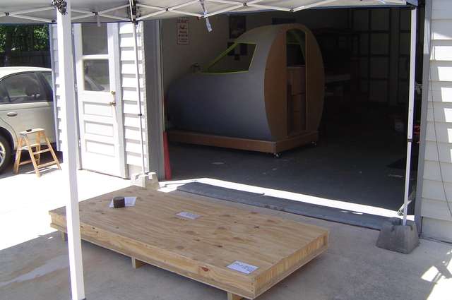

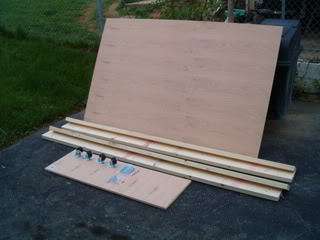
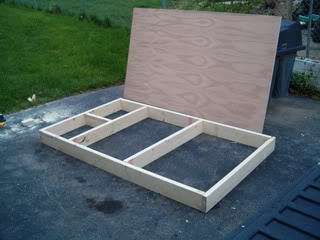
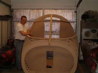
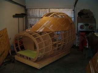
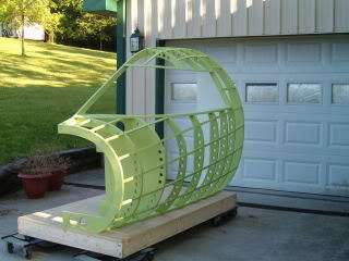
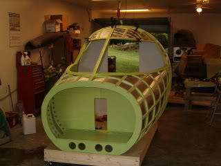
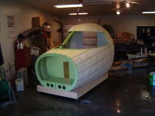
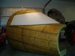
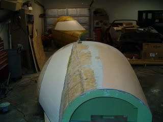
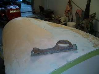
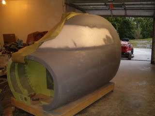
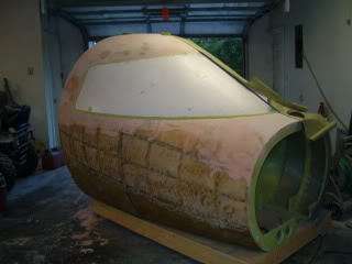
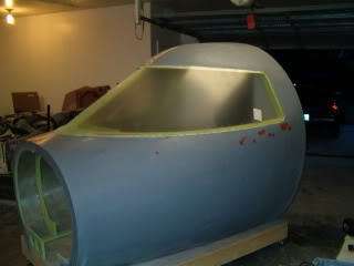
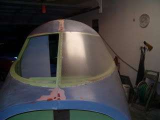
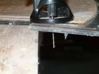
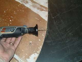
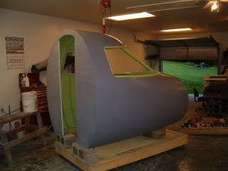
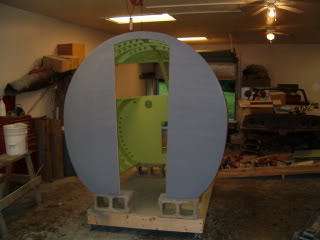
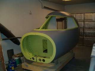
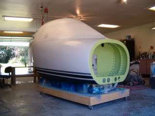
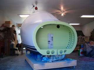
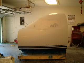
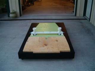
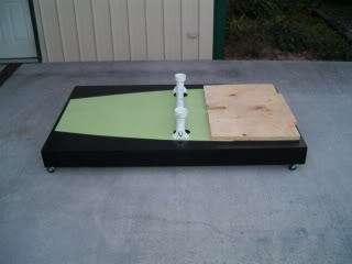
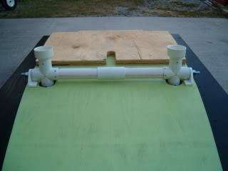
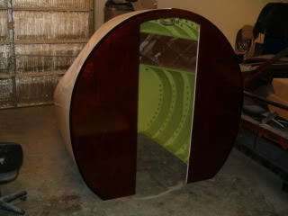
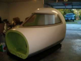
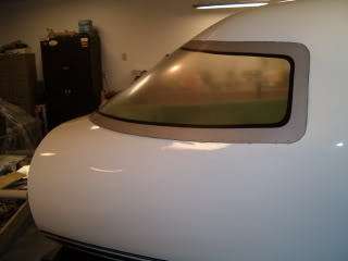
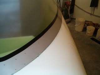
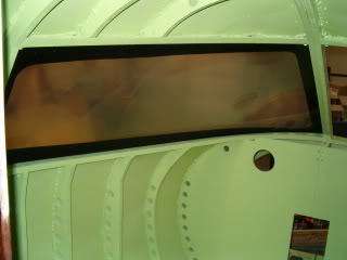
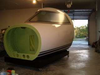
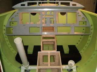

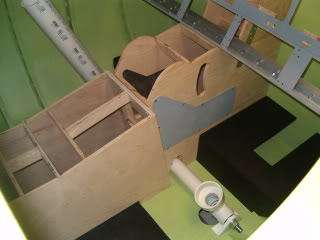
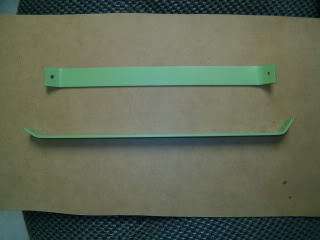
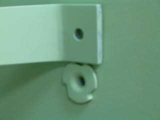
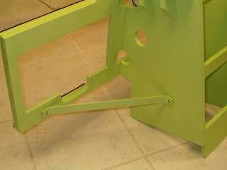
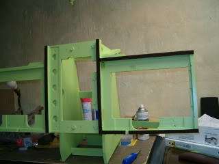

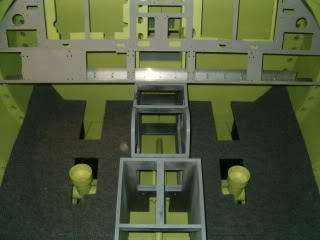
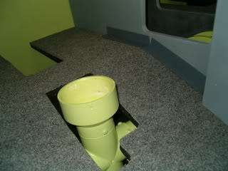
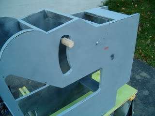
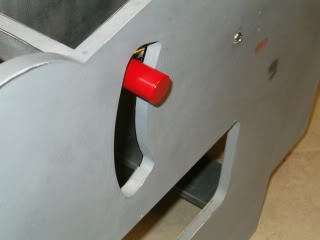
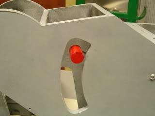
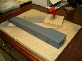
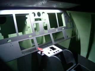
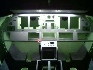


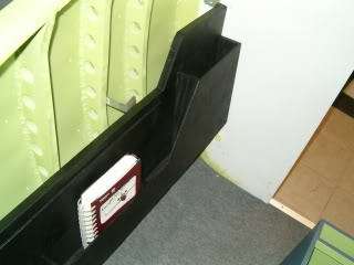
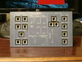
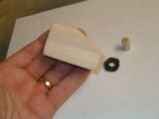
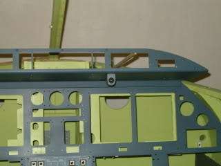
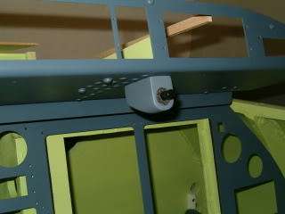
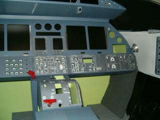
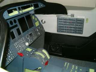
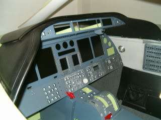
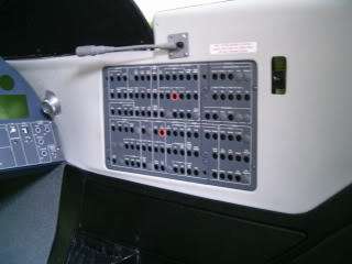
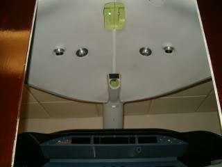

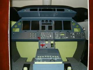
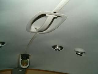
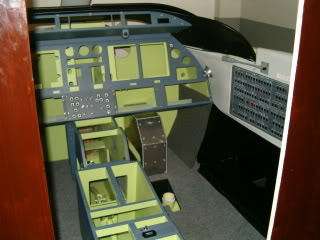
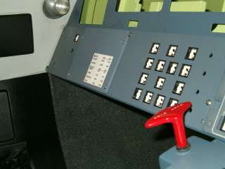
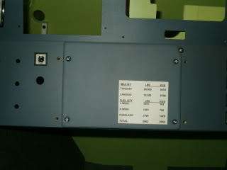
![]()
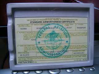
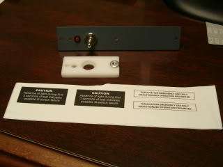
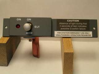
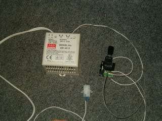
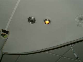
![]()
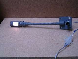
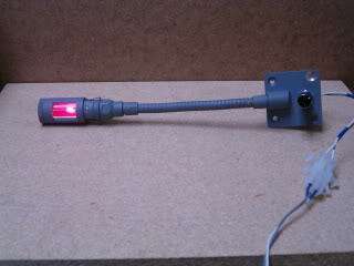
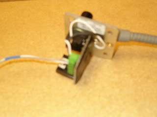
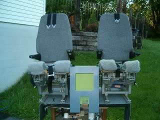
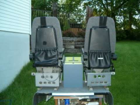
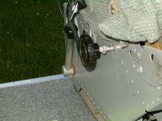

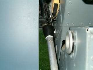
![]()

![]()
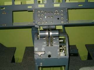
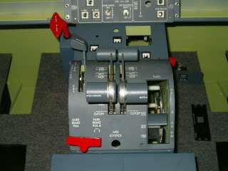
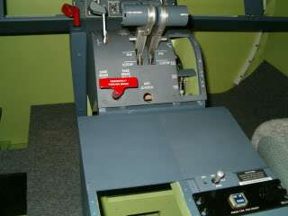
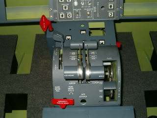
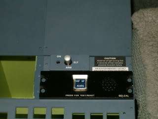
![]()
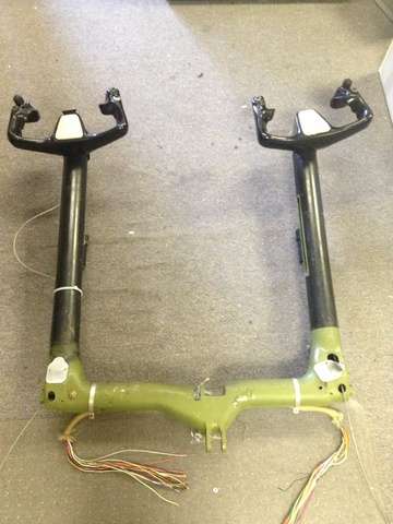
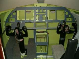
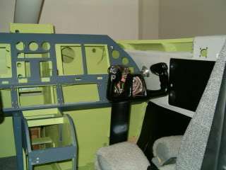


![]()
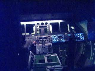
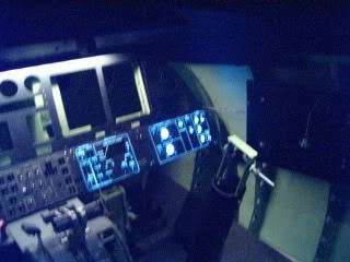
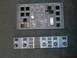
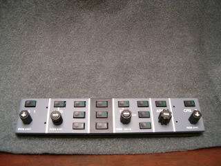
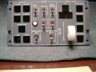
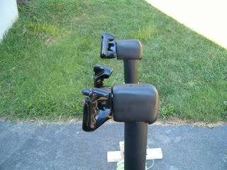
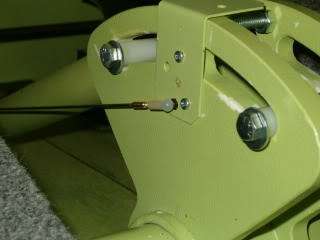
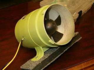
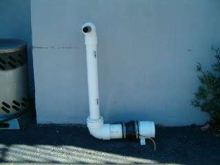

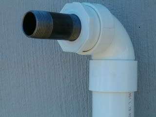
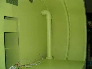


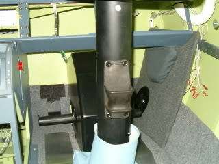
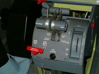
![]()

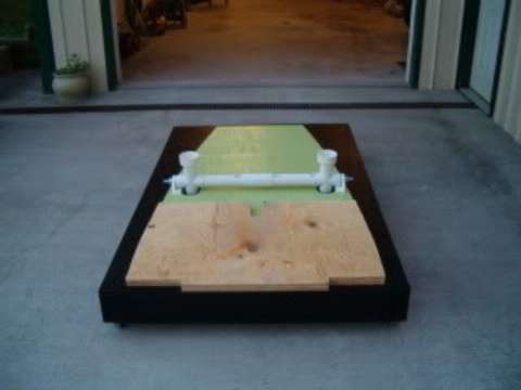
![]()
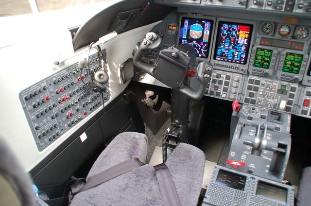
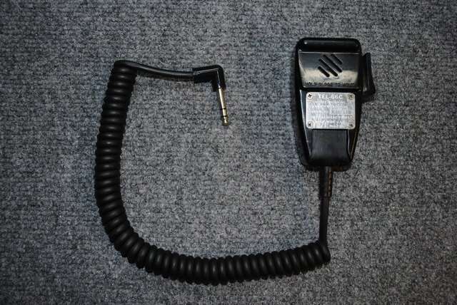

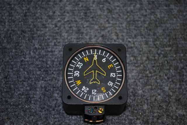
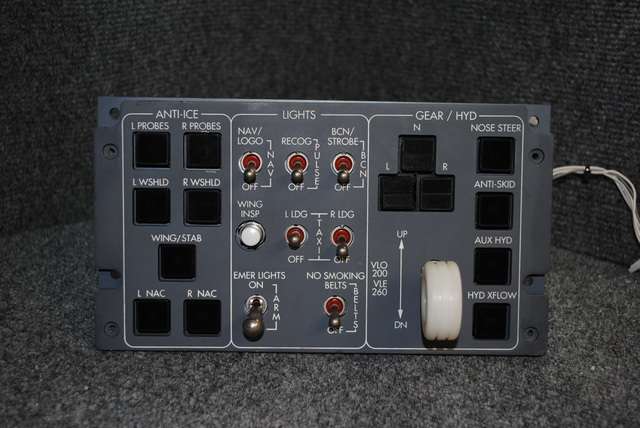
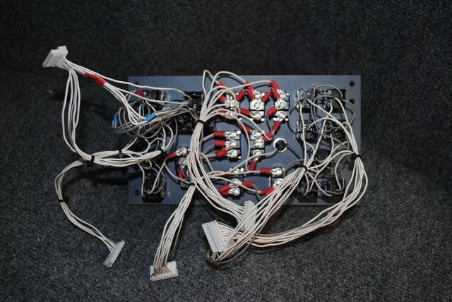
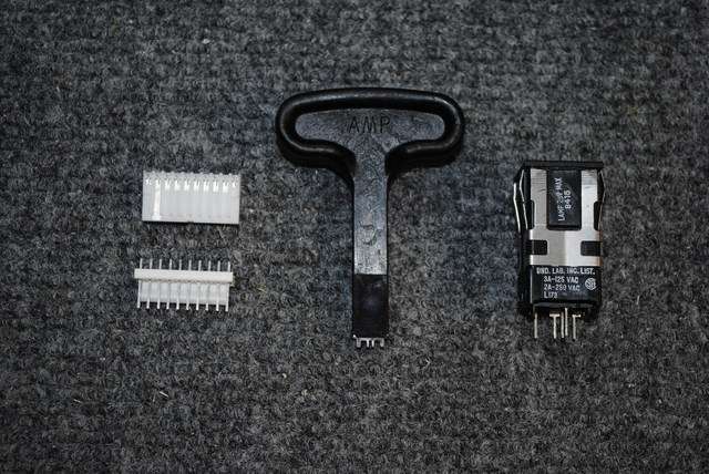
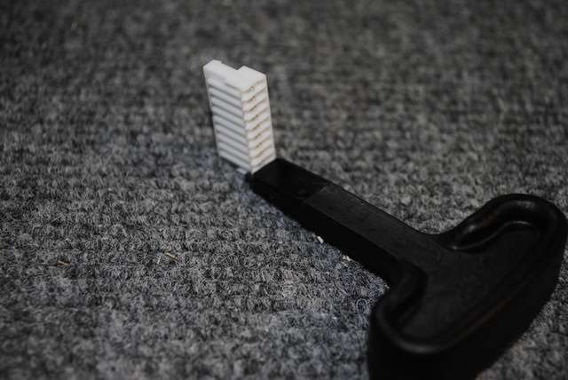
![]()
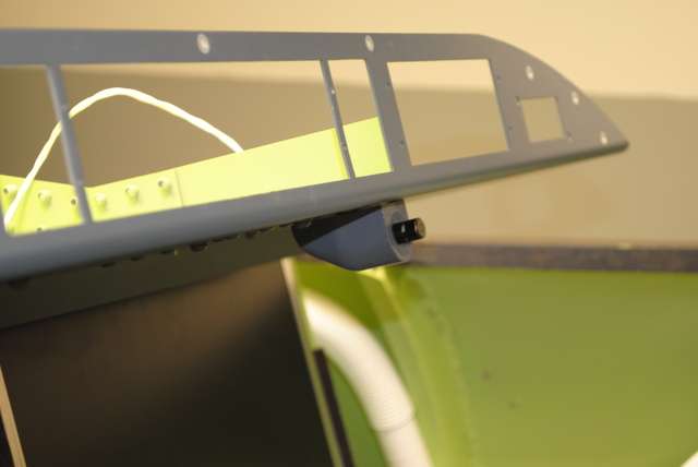
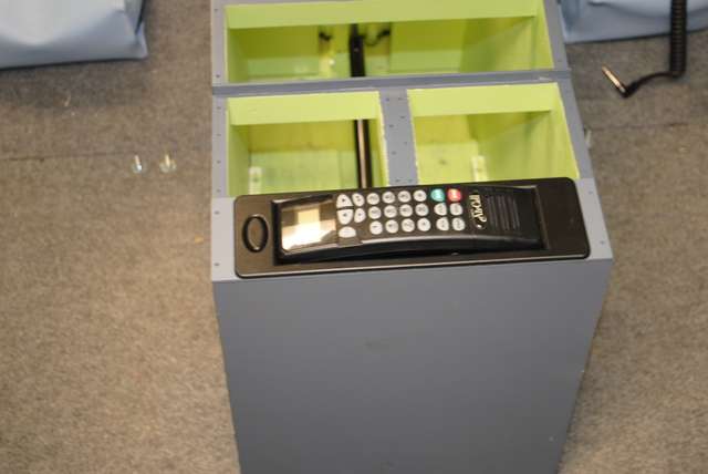
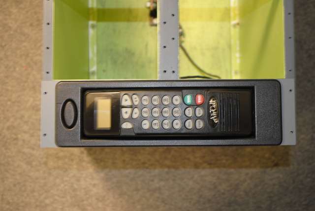
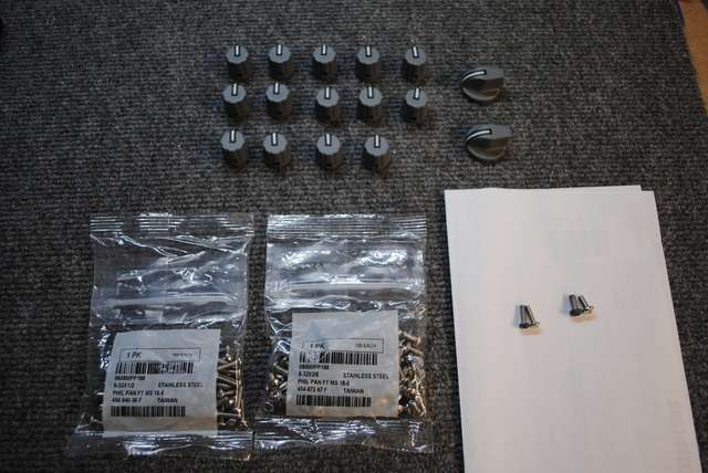
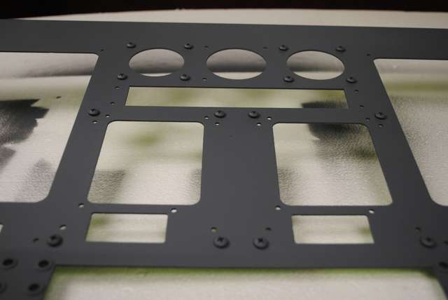
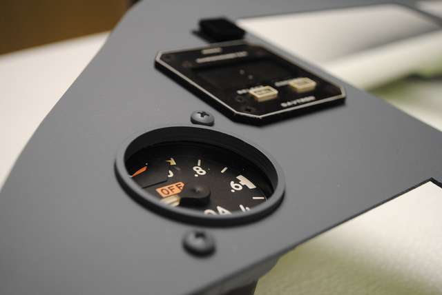
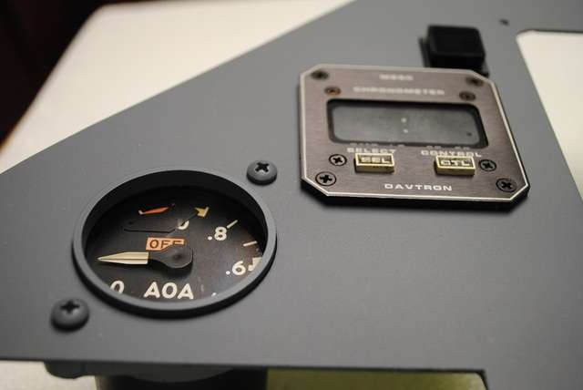

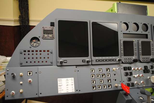
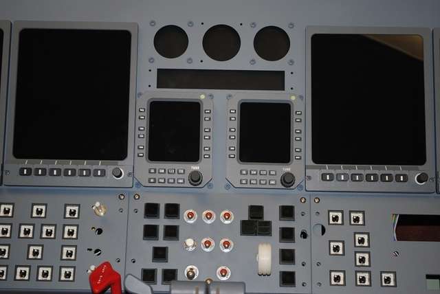
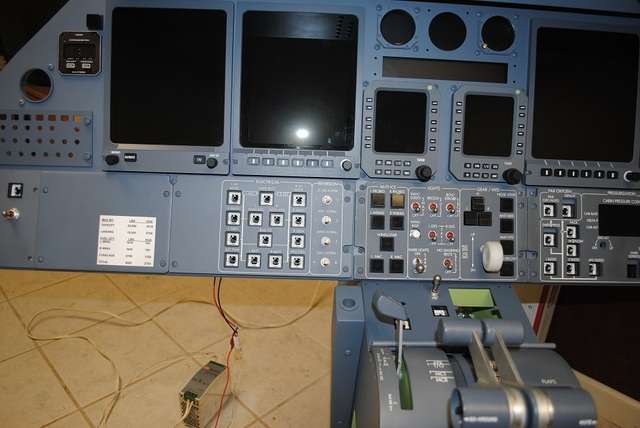
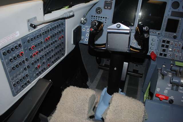
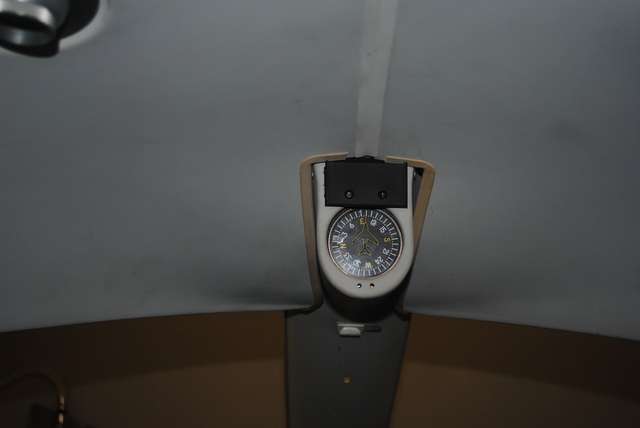
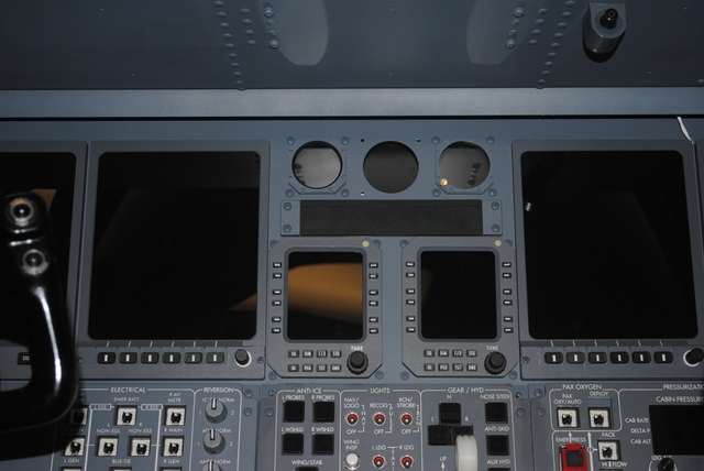
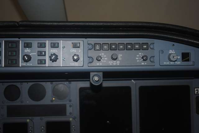
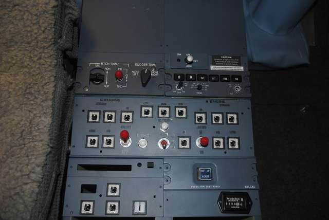
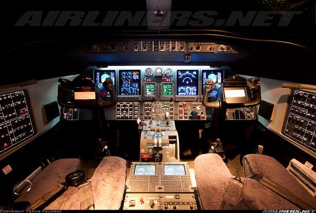
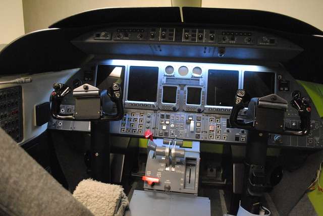
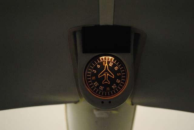
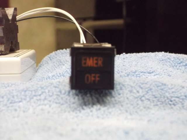

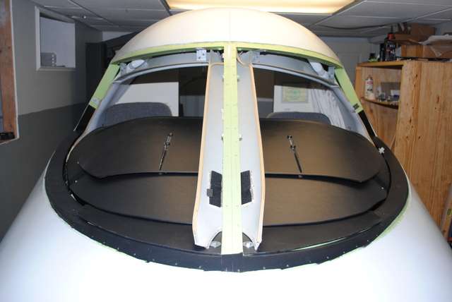
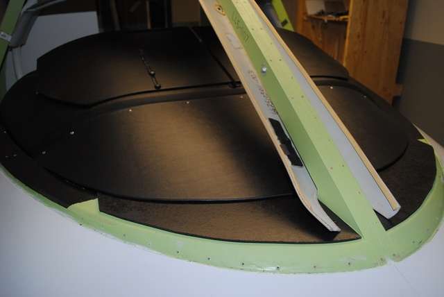
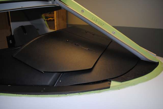
Forum NavigationShane Barnes L45-007 Project Updates!
![]() #1 · November 24, 2017, 10:16 pm
#1 · November 24, 2017, 10:16 pm![]() #2 · November 27, 2017, 9:52 pm
#2 · November 27, 2017, 9:52 pm![]() #3 · November 27, 2017, 10:02 pm
#3 · November 27, 2017, 10:02 pm![]() #4 · November 27, 2017, 10:09 pm
#4 · November 27, 2017, 10:09 pm![]() #5 · November 27, 2017, 10:15 pm
#5 · November 27, 2017, 10:15 pm![]() #6 · November 27, 2017, 10:23 pm
#6 · November 27, 2017, 10:23 pm![]() #7 · November 27, 2017, 10:45 pm
#7 · November 27, 2017, 10:45 pm![]() #8 · November 28, 2017, 11:50 pm
#8 · November 28, 2017, 11:50 pm![]() #9 · November 30, 2017, 2:35 pm
#9 · November 30, 2017, 2:35 pm![]() #10 · November 30, 2017, 3:18 pm
#10 · November 30, 2017, 3:18 pm
2017-10-10