


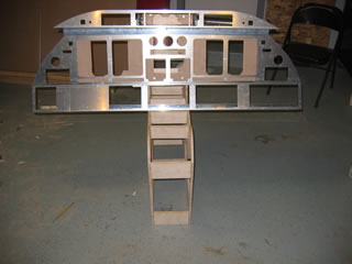
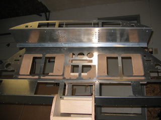
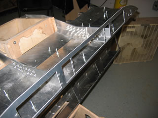
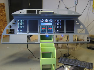
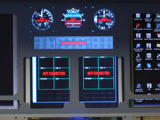
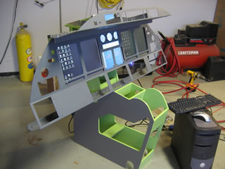
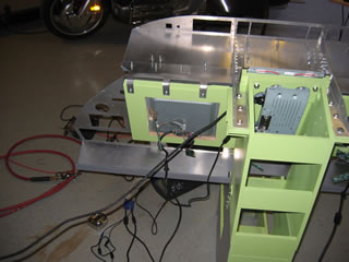
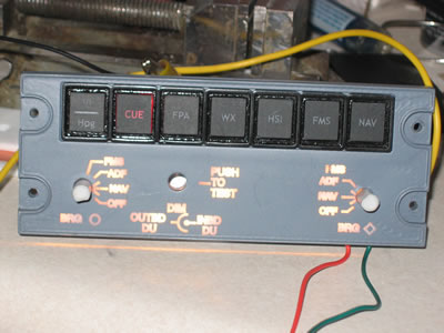
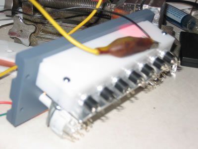
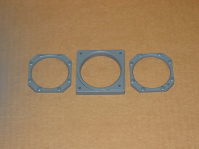
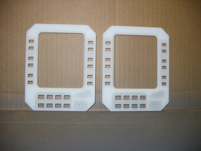
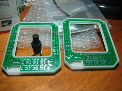
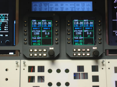
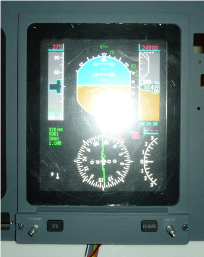
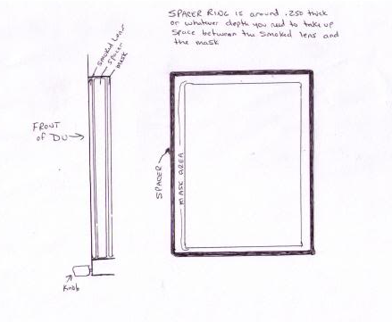
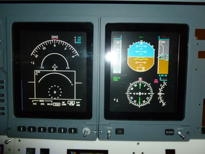
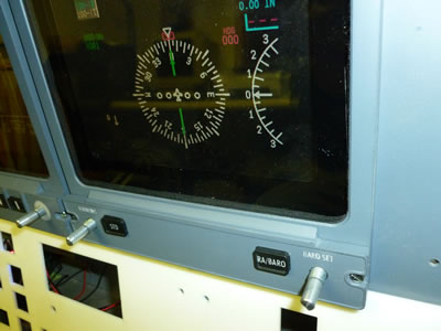
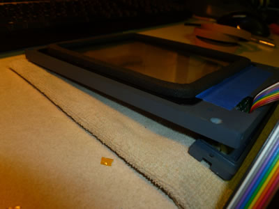
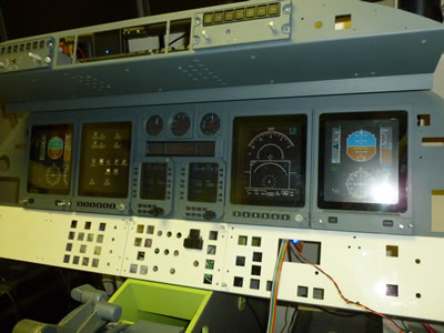
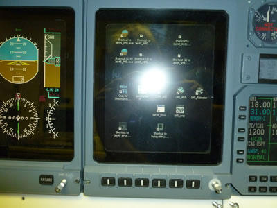
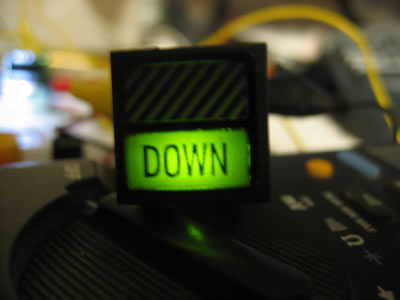
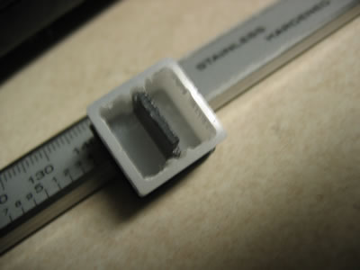
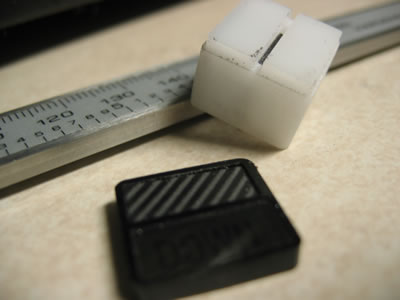
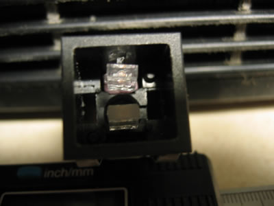
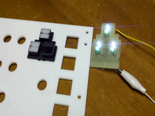
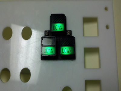
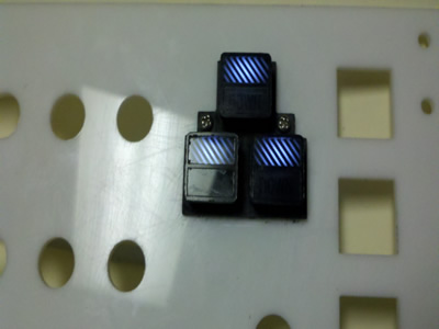
(Original thread started on 08-02-09 by Mark Lichtscheidl) Well, I didn't make it to paint this weekend, but I did complete the build or this stage of it. Now it's time to tear it down and prep and give it some paint! If you are going to build one of these, you need to have your 3 LCD monitors for building up the MIP backer. But MOST important! Tear them ALL apart to verify that they ALL have the SAME GUTS! My 2 15" E-Machine LCDs are the same model but different guts! I had only broken down the 1 monitor and used that to layout the backer to support the LCDs. After paint and I was reassembling tonight and broke down the other monitor when I discovered this. Guess what, it didn't fit! So I had to tear it apart and make mods to my backer for that monitor. Good thing I had the afternoon off and had the time to do this. So everything is back together and it looks gorgeous! Pics tomorrow night, got to late tonight. So just remember break everything down regardless if it's the same from the outside. (Posted by Eric Tomlin on 08-06-09) Mark, what happened to you is exactly what happened to me. Ron found the monitors that he felt was the best suited for our projects using the same parts you, Shane, and Scott now have or will soon have. I ordered the suggested monitors and BOTH were just different enough from the ones Ron had (same model # too) that we had to make a different LCD support just as you have. (Posted by Mark L. on 08-06-09) Okay, Gave it the final coat of Testor's Gunship Gray and reassembled, plugged in the LCDs for an ops check. All systems go! JASON! I need some software!! Have some details to button up, but wanted to see if everything turned out alright. Whew! glad that parts over! I think I'll hold off on enlarging anything until I get to where I have it in hand and see exactly what needs to be done. It should have or would have been easier to modify before the MIP was bent, but I was unaware at the time of the mods to the DU openings. I also wanted to give a big huge thanks to Dave Ault and his gauges again. They look and work awesome, especially within the MIP panel. I'm aware of the time and effort it took to create those and deserves extra credit for these. (Posted by Dave Ault on 08-07-09) Its looking fantastic Mark. Thanks for your kind words, glad you are finding the Gauges useful, To see them running in other peoples simulators makes it all worthwhile. (Posted by Mark L. on 11-15-09) Thought I'd show off my prototype of the EFIS panel. Couple of things I found out, I should have done a resurface of my bed before attempting to engrave the back lighting circuit, not to mention the engraving of the front panel itself. I was about 5-8 thousandths off in a 6" length, big difference when it comes to engraving. I also need to find the correct font, the one I used looked great in the preview, not so much when engraved. I'm still missing the center dimming switch, I need to figure out what I need here. I also haven't ordered the red LED's I need for these yet, I was waiting until I knew for sure what I needed. Currently testing with a 3k MCD, but I want to try one about half that to see how it does. You may notice some mill marks that are hard to reach for sanding. However, I've found a newer technique with my milling to greatly minimize this, so hopefully the next one to replace this one will come out a lot better. My approach on this was to make all 7 switches within a single block, to me this seemed simpler, eventually there will be a small circuit board to connect the LED's with a some type of wire connector for them. The next version, I will probably use some low profile tactile switches like Vince uses, the Radio Shack momentary switches I"m using don't impress me. The back ligting was done with the bulbs laying down (holy smokes do they get warm!). Outside of the cosmetic issues, it came out pretty good and functions as designed: NOTE: (By Hangar45 admin) So that there is no confusion with other members and builders, the buttons on the EFIS do not illuminate RED. The switches are constantly illuminated white via back lighting. They don't have a color when pressed, as the mode is annunciated via the PFD, and by that, when you make a change on the display controller (the EFIS panel) it's apparent on the PFD that you've made that desired change. UPDATE: Here it is with the redone face plate. Engraving came out much nicer. Still might look a little fuzzy, but it's because I need a new camera. The focus has gone wacko on it. I'm laying the bulbs flat on this particular piece and thinking about milling out a recess of the entire area to be backlit when close together rather than separate holes for each bulb. It is so important to have the engraved area flat to the same height. It's even harder to do on the scissor cut copper I have because it's so thin and to get the entire area to lay flat. (Posted by Mark L. on 02-03-10) Been a little quite the past couple of weeks with the holidays. Not major or complicated components to make, but these bezels for the Analog gauges just came out of the paint nursery! (Yep Eric, CNC got knocked up again!) I'll pop the lenses in and mount them once the paint is good and setup. I have to mount the knobs on the attitude and altitude gauges and will be static for now because of the lack of space to make something work and the time it will take to address this if at all possible: Boy, you gotta be careful now days! I fed some of Vince's code into my CNC and it got knocked up yet again and spit these lovely pair of twins out! WooHoo! I've got RMU Panels! Still have to finish up the other components of it and paint, but this was the hard part I think. 2 tries, 2 successful pieces! Produced from Vince's DIY kit: I have to say that the quality of the code Vince put into these is 2nd to none. His code dropped into my machine and cut it perfectly. I got an education in some of things he does that will definitely help me produce parts with the same quality. Though he has set the bar pretty high. The trickiest part is the alignment when you flip the part over and I took extra time with that step. The coolest part is the circuit board he shipped with the kit fit perfectly to fractions of a millimeter. Looking forward to finishing these off and hooking them up. Pic of the backside with how well the PCB drops in: Link to Full size pic click HERE UPDATE: I finished my RMU's and installed them! Even in kit form, this was considerable effort, I almost envy those that get to simply bolt them up. But I know them as well as Vince does now. I still have to build my dimmer circuits, so these are on at full intensity, but looks mighty fine and here's the finished result: (Original thread started on 08-02-09 by Mark Lichtscheidl) Well, I didn't make it to paint this weekend, but I did complete the build or this stage of it. Now it's time to tear it down and prep and give it some paint! If you are going to build one of these, you need to have your 3 LCD monitors for building up the MIP backer. But MOST important! Tear them ALL apart to verify that they ALL have the SAME GUTS! My 2 15" E-Machine LCDs are the same model but different guts! I had only broken down the 1 monitor and used that to layout the backer to support the LCDs. After paint and I was reassembling tonight and broke down the other monitor when I discovered this. Guess what, it didn't fit! So I had to tear it apart and make mods to my backer for that monitor. Good thing I had the afternoon off and had the time to do this. So everything is back together and it looks gorgeous! Pics tomorrow night, got to late tonight. So just remember break everything down regardless if it's the same from the outside. (Posted by Eric Tomlin on 08-06-09) Mark, what happened to you is exactly what happened to me. Ron found the monitors that he felt was the best suited for our projects using the same parts you, Shane, and Scott now have or will soon have. I ordered the suggested monitors and BOTH were just different enough from the ones Ron had (same model # too) that we had to make a different LCD support just as you have. (Posted by Mark L. on 08-06-09) Okay, Gave it the final coat of Testor's Gunship Gray and reassembled, plugged in the LCDs for an ops check. All systems go! JASON! I need some software!! Have some details to button up, but wanted to see if everything turned out alright. Whew! glad that parts over! I think I'll hold off on enlarging anything until I get to where I have it in hand and see exactly what needs to be done. It should have or would have been easier to modify before the MIP was bent, but I was unaware at the time of the mods to the DU openings. I also wanted to give a big huge thanks to Dave Ault and his gauges again. They look and work awesome, especially within the MIP panel. I'm aware of the time and effort it took to create those and deserves extra credit for these. (Posted by Dave Ault on 08-07-09) Its looking fantastic Mark. Thanks for your kind words, glad you are finding the Gauges useful, To see them running in other peoples simulators makes it all worthwhile. (Posted by Mark L. on 11-15-09) Thought I'd show off my prototype of the EFIS panel. Couple of things I found out, I should have done a resurface of my bed before attempting to engrave the back lighting circuit, not to mention the engraving of the front panel itself. I was about 5-8 thousandths off in a 6" length, big difference when it comes to engraving. I also need to find the correct font, the one I used looked great in the preview, not so much when engraved. I'm still missing the center dimming switch, I need to figure out what I need here. I also haven't ordered the red LED's I need for these yet, I was waiting until I knew for sure what I needed. Currently testing with a 3k MCD, but I want to try one about half that to see how it does. You may notice some mill marks that are hard to reach for sanding. However, I've found a newer technique with my milling to greatly minimize this, so hopefully the next one to replace this one will come out a lot better. My approach on this was to make all 7 switches within a single block, to me this seemed simpler, eventually there will be a small circuit board to connect the LED's with a some type of wire connector for them. The next version, I will probably use some low profile tactile switches like Vince uses, the Radio Shack momentary switches I"m using don't impress me. The back ligting was done with the bulbs laying down (holy smokes do they get warm!). Outside of the cosmetic issues, it came out pretty good and functions as designed: NOTE: (By Hangar45 admin) So that there is no confusion with other members and builders, the buttons on the EFIS do not illuminate RED. The switches are constantly illuminated white via back lighting. They don't have a color when pressed, as the mode is annunciated via the PFD, and by that, when you make a change on the display controller (the EFIS panel) it's apparent on the PFD that you've made that desired change. UPDATE: Here it is with the redone face plate. Engraving came out much nicer. Still might look a little fuzzy, but it's because I need a new camera. The focus has gone wacko on it. I'm laying the bulbs flat on this particular piece and thinking about milling out a recess of the entire area to be backlit when close together rather than separate holes for each bulb. It is so important to have the engraved area flat to the same height. It's even harder to do on the scissor cut copper I have because it's so thin and to get the entire area to lay flat. (Posted by Mark L. on 02-03-10) Been a little quite the past couple of weeks with the holidays. Not major or complicated components to make, but these bezels for the Analog gauges just came out of the paint nursery! (Yep Eric, CNC got knocked up again!) I'll pop the lenses in and mount them once the paint is good and setup. I have to mount the knobs on the attitude and altitude gauges and will be static for now because of the lack of space to make something work and the time it will take to address this if at all possible: Boy, you gotta be careful now days! I fed some of Vince's code into my CNC and it got knocked up yet again and spit these lovely pair of twins out! WooHoo! I've got RMU Panels! Still have to finish up the other components of it and paint, but this was the hard part I think. 2 tries, 2 successful pieces! Produced from Vince's DIY kit: I have to say that the quality of the code Vince put into these is 2nd to none. His code dropped into my machine and cut it perfectly. I got an education in some of things he does that will definitely help me produce parts with the same quality. Though he has set the bar pretty high. The trickiest part is the alignment when you flip the part over and I took extra time with that step. The coolest part is the circuit board he shipped with the kit fit perfectly to fractions of a millimeter. Looking forward to finishing these off and hooking them up. Pic of the backside with how well the PCB drops in: Link to Full size pic click HERE UPDATE: I finished my RMU's and installed them! Even in kit form, this was considerable effort, I almost envy those that get to simply bolt them up. But I know them as well as Vince does now. I still have to build my dimmer circuits, so these are on at full intensity, but looks mighty fine and here's the finished result: (Posted by Vince C. on 02-04-10) A CNC is something like the "Holy Grail" of parts making. I mean, you think of a part, plan it on a computer and build it with the machine! It takes though a lot of efforts to learn the software, hardware, production techniques and so on. It is a hobby within hobby! (Posted by Mark L. on 12-18-11) So I thought I'd have my DU's mounted this weekend, looks like sometime this week. I got them in a trial DIY kit that Vince and I tried out. While it went pretty good, if your not on top of your game with the CNC then it may not be the best option. Turned out not to be an option Vince wanted to continue because of the custom G code changes to support my bits and materials, ie: the world of metric vs Imperial. So anyway, got them assembled as far as cutting, milling, electronics, painted and engraved and then realized I still had to get material to make the lenses. I then opted for the 'painted mask' treatment that Ron did. Later if I decide to I might try Shane's idea with the tinted smoke grey. A little reluctant right now to go that route as it would dim the displays some. So anyway, paint is drying and hopefully tomorrow or Tuesday I can get them mounted on the MIP! So many details to address even with a well put together component. New design/prototype for my EFIS unit is complete! I just did a quick few shots with my Droid and uploaded to Facebook, I'll get some decent shots put up soon. I went with a solid thicker front panel as to 'house' the buttons and 2 PCB's to finish the job. One for the back lighting using SMD LED's and the rear PCB to hold the tactile, rotary and encoder switches. I don't have this one cabled up yet, but that will come soon. Of course during prototyping mistakes happen, I broke the tip off of my 45 deg engraving bit and substituted a 60. Didn't come out as nice and while cutting the buttons, the NAV button decided to let go and got whacked by the bit as it flew out, so I'll have to be more careful on the final pieces. Still, it turned out really good I think, much better than my last approach using cheap momentary buttons I got from Radio Shack. The 'flooding' looks worse is in the pics than it really is, I don't have a dimmer hooked up in these shots, so they're running full bright. UPDATE: Here's a pic with the DU in place. The protective coating is still on the lens so it doesn't look pretty, but you can see the size of the mask I created. Looks like it should be fine, but I'm having the same problem Eric G did. I'm unable to resize the PFD to the area available. It seems to only go so large. You can just barely see the edge of the monitor frame, I don't have the black foam edge behind the mask installed yet, so this otherwise wouldn't be visible. I may also as Shane did, paint that chrome frame black to be on the safe side: I got the foam strip from Vince, my local Menards (Home Supply store) had the same thing along with different sizes, so there's usually something that will fit or can be easily cut to size. I plan to use a few drops of glue on the backside to secure mine along with the foam behind the lens will help keep in place. The lens fits to the front of the backside of the DU bezel followed by the foam to help hold and block out any light coming from the other windows open on that display such as the RMU or neighboring PFD or MFD. Some allowances have to be made for not having the real thing. (Posted by Alan Norris on 12-19-11) It seems as if the strips of black foam should be attached to the MIP at the edge of the DU openings? If it goes into the opening at the back of the DU bezel then there is still space between the MIP and monitor. Am I missing something? (Posted by Mark L. on 12-19-11) The foam strip has to be wide enough to cover the distance. The strip is applied to the sidewall of the DU bezel behind the lens. So a .5" to .75" wide strip should easily cover the distance, in my case it does. After playing with the positioning etc, I can see now I have to make a change and what Ron was talking about. I will be using 2 pieces of 'lens' in my DU's now. A clear lens at the front of the DU and the 'masked' lens at the back of the DU, to place the 'masked' part closer to the monitor. With the masked lens at the front, it just doesn't look right. So off to the store this week to pick up some more clear material to make another set of clear lenses. (Foam will now also go behind the 'masked' lens to provide 'blocking'.) (Posted by Shane Barnes on 12-19-11) In reference to your DU bezels, I did a quick drawing hopefully you can read it. Basically the idea is to lay your DU face down, then install the smoked lens or whatever lens you are using into the opening of the DU. This lens will go all the way forward to the front of the DU, then install a spacer that will take up the space from the front of the DU to the back leaving enough room for your mask to sit flush with the back of the DU. The spacer ring is thin so you will not see the spacer it is only about the thickness of the lip or a little more that is around the DU opening to hold the lens in place and keep it from coming out the front of the DU. I painted mine black so it blends in with the mask but with the smoked lens you can't see it anyway. The spacer and the mask are glued together then painted black so it is one unit. I did not glue the smoked lens in place. It is held by the mask/spacer which is glued in place so I don't have to worry about the glue causing any haze in the lens. Your lucky having the later version of the MIP. My lens would fall out the back if not glued in place! (Posted by Mark L. on 12-19-11) So is this 'ring' one continuous piece? Being cheap lately, that sucks up a bunch of plastic to make that. Stock .125" cast acrylic sandwiched between gives me a perfect flush fit with the back. Clear lens, 'ring' and masked lens, problem is with a clear front it's visible sort of depending on big I make this (width of ring). I thought about using some screen door bead, but decided not to as I would have to super glue it in place. Too much of a drop and the glue with burn/haze the lens. Maybe I'm just be overly cautious? I was thinking that if I have to use the plastic to make the ring, then why not make a ring that is half the distance of the mask with the same shape painted gray. So then you would have the DU Bezel, lens, ring with mask shape to reduce the visible area and then the lens with the mask. As I have one like #3 of the MIPS being cut by Tom, my cutouts are smaller allowing the rear most lens to sit flush against the MIP so it can't fall out. (Posted by Shane Barnes on 12-19-11) Yes the ring is one piece. I see where you are going to have a problem with the clear front because you would see the spacer/ring. As for the ring, mine is just a little wider (going from memory here) than the lip inside the DU opening but I can get away with this due to the smoked lens . . you can't see it because it blends in with the mask that is painted black. I think Ron went a different route . . I don't think he has a lens in the front of his DU. I think his lens is at the back of the DU and maybe he painted his mask on his lens. I think he used Vince's foam to fill the void from the front of the DU to where his lens/mask is attached. I don't know if he has changed any of that as I think that is what he was going to do at one point. Most of this issue is why I looked at the options and opted for the smoked lens because it covers up all of this and because I had to have a way to hold my lens in with the bigger cutouts of my MIP. I did some testing prior to going this route to see how much it cuts down on the brightness of the monitor and it was not enough to concern me. Once again I think I am the oddball going this route but I had to engineer what was going to work with the MIP I had. (Posted by Eric Tomlin on 12-20-11) Look at a real LJ45 DU. The lenses are dark/smoked and there's a "gap" between the DU frame (we're talking internally here) and the viewable area of the CRT screen used in the older Primus 1000 system just like your old CRT television has/had. By placing either a 2nd thin sheet of material there in front of the actual LCD screen, you create the illusion of having a CRT vs. an LCD screen. Ron painted a black CRT ring on the back of his FRONT lens. For Shane, I cut him a replacement smoked lenses, a spacer, and then a CRT gap sheet. All of this then goes into the back of the DU and the spacer was to place the CRT ring back against the front of the LCD. If not, then it'd be wrong looking since in the real DU, it's actually a part of the screen itself (and obviously we cannot do that here with an LCD, so we place the ring simulator part right on top of the LCD). What we are trying to do is replicate as close as possible the look of the CRT in a real Lear45. (Posted by Ron Rollo on 12-20-11) As for the DU bezels, we want something that looks good and is also functional. This is why I placed my lenses as close to the aluminum MIP as possible with black paint on the back of the lenses replicating a bezel to hide the aluminum bezels on the LCD screens. Therefor the lenses needed to be as close to the LCD screens as possible so that you could not see things (aluminum bezels on LCD screens) when viewing at an angle. As an example, from the pilot's point of view, D1 and D2 would look great if the lenses were further aft, or away from the LCD screens. But viewing D3 and D4 from the pilot's POV would show the aluminum bezels. This is why we want the lenses as close to the LCD as possible. Going this route makes the DU's look more like CRTs. That's fine with me. They look good and are very functional. Then I took black foam strips and filled the gap between the front side of the lenses and the front of the DU. (Posted by Mark L. on 12-20-11) The problem is that right away you have this obvious depth perception issue. Not that you can't determine the depth, but he black mask makes it more apparent how far away the lens is from the monitor. By putting a clear lens in the front and the masked lens at the rear of the DU frame, it looks tremendously better. However, I'm debating if I need to put some type of spacer between the lenses. Since I'm using clear (maybe smoked down the road) anything I put between them will be visible. There's not much of a lip to hide anything, so yes, I can paint the spacer to blend in better (grey or black?), but even then it's a very small ring to cut and wastes a huge amount of plastic to do it. I'm also debating about just putting spacers in the corners where it will be hidden better. As Eric and Shane have done, the front lens can be tinted which hides it more, but dims the display. I guess if I had a piece to compare with it would help, but the clear isn't that bad of a option. UPDATE: Well, I decided it was time to do something, so I went with slitting off the width I needed from the weatherstripping Vince sent with the DU's for the space between the lens. This appears to have worked pretty well and I'm happy with it, though it's a tedious time consuming process. If I get another one done and mounted, I'll take a pic tonight, otherwise tomorrow. It also works to kill any light bleed that could have occurred. I've got two done except for putting some foam stripping behind the masked lens to rest against the monitor and it won't take much to do that. I like the result and happy I went this direction. So these have a front clear lens with very thin weather stripping followed by the rear lens that has the painted mask. This sits flush with the back of the DU frame. This puts the mask within .25" or less from the monitor and gives a nice effect: Here's a close up of the weather stripping between the lenses: Got them done and in except for fitting the knobs and painting the screws. Close up of backside of DU, pic didn't turn out so good, but can see weatherstripping applied to back of the masked lens: MIP is looking alot more towards the complete stage suddenly! Close up of DU showing the weatherstripping between the lenses and the one behind. Camera light really shows off the static cling dust. Guess I should have wiped it down better: (Posted by Mark L. on 08-11-12) Here is my landing gear indicator light pack solution. My advanced method for this works like a champ. Same as what Rand has presented only in reverse. I did the "XOrion" LED conversion and bent it with an offset to lower the position of the LED. The upper one, was just a slight bend. The leads were actually long enough to go right out the back so they can be soldered up to. (I noticed this 'Yellow' looks more orange, what's with that?) Running 5v with 100 and 140 ohm resistors with no noticeable difference. Okay, on to the adapter block, I milled out the 'crown' as I call it to accept Ron's great lens assembly, flipped it over and milled out the entire backside with a channel for the divider to fit into to hold it in place. I had to modify the divider a little for this mod, but got a nice snug fit. Led position turned out perfect. Hopefully the pics show it well enough, on the one, it might look like bleed, but is just reflection. So Rand, I think this worked out better as I wasn't able to get the LED's thru the original switch lens holder nor position the divider the direction we needed: This is really bugging me. Rand, what voltage and what size resistor are you using on your Yellow LED's. It is the part number 276-0010 right? It states FW current at 20ma and FW Voltage at 1.9 typical, 2.4v max. I've varied the resistance from 100 ohms to 180 ohms with no change, still orange. Yours definitely look yellow. While I had hoped for 100% success on this, I have to settle for what I'll call 95% until this weekend. Using a design that Vince had shown sometime back to handle the Gear Indicator block issue, I had no desire to trash 2 or 3 more expensive switches only to not have a solution. So using Vince's design, from what I could tell, he had 3 separate blocks he made to complete the indicators. I decided to make it all in one piece. I also designed it to recess into the backer plate using the existing holes previously cutout for the AML21 switches. I also did not follow Vince's lead where he left the top open where the lens goes, as I wanted some diffusion to occur rather than chance a focused bright spot from the led. Then I fabricated a PCB to attach from the back side of the backer plate for the led circuits and hold the LED's themselves. You will notice that the green isn't showing up and that's the problem. I could have sworn I ordered the correct LED's (months ago), but they are only 12 MCD, not going to cut it. So I ordered some 5000 MCD green 3mm LED's tonight that will be here this weekend and will be replacing the current ones, which will show up as anticipated. The back side of the block may look burnt, but it's just paint that got a little smudged and I haven't sanded it down yet. Anyway, I found this to be a nice clean easy solution for me, took awhile to crank up the G-code, but maybe a couple of hours to cut the part and the PCB. I will solder wires onto the PCB to run the leads to whatever controller I end up using for this. Hard wired all LED's on for testing: Updated the LED's and finished the installation to the backer plate and coding with OpenCockpits: Video of the Gear Indicators in action starting from Gear Down to Gear Up and back to Gear Down: https://youtu.be/G9WnmyU_QrY Additionally, here's one for the Master Switch list I created: [url]http://www.markdidit.com/Project45/MIP/LowerPanels/project45_mip_lowerpanels.pdf[/url] UPDATE: This build thread has been retired! (Posted by Vince C. on 02-04-10) A CNC is something like the "Holy Grail" of parts making. I mean, you think of a part, plan it on a computer and build it with the machine! It takes though a lot of efforts to learn the software, hardware, production techniques and so on. It is a hobby within hobby! (Posted by Mark L. on 12-18-11) So I thought I'd have my DU's mounted this weekend, looks like sometime this week. I got them in a trial DIY kit that Vince and I tried out. While it went pretty good, if your not on top of your game with the CNC then it may not be the best option. Turned out not to be an option Vince wanted to continue because of the custom G code changes to support my bits and materials, ie: the world of metric vs Imperial. So anyway, got them assembled as far as cutting, milling, electronics, painted and engraved and then realized I still had to get material to make the lenses. I then opted for the 'painted mask' treatment that Ron did. Later if I decide to I might try Shane's idea with the tinted smoke grey. A little reluctant right now to go that route as it would dim the displays some. So anyway, paint is drying and hopefully tomorrow or Tuesday I can get them mounted on the MIP! So many details to address even with a well put together component. New design/prototype for my EFIS unit is complete! I just did a quick few shots with my Droid and uploaded to Facebook, I'll get some decent shots put up soon. I went with a solid thicker front panel as to 'house' the buttons and 2 PCB's to finish the job. One for the back lighting using SMD LED's and the rear PCB to hold the tactile, rotary and encoder switches. I don't have this one cabled up yet, but that will come soon. Of course during prototyping mistakes happen, I broke the tip off of my 45 deg engraving bit and substituted a 60. Didn't come out as nice and while cutting the buttons, the NAV button decided to let go and got whacked by the bit as it flew out, so I'll have to be more careful on the final pieces. Still, it turned out really good I think, much better than my last approach using cheap momentary buttons I got from Radio Shack. The 'flooding' looks worse is in the pics than it really is, I don't have a dimmer hooked up in these shots, so they're running full bright. UPDATE: Here's a pic with the DU in place. The protective coating is still on the lens so it doesn't look pretty, but you can see the size of the mask I created. Looks like it should be fine, but I'm having the same problem Eric G did. I'm unable to resize the PFD to the area available. It seems to only go so large. You can just barely see the edge of the monitor frame, I don't have the black foam edge behind the mask installed yet, so this otherwise wouldn't be visible. I may also as Shane did, paint that chrome frame black to be on the safe side: I got the foam strip from Vince, my local Menards (Home Supply store) had the same thing along with different sizes, so there's usually something that will fit or can be easily cut to size. I plan to use a few drops of glue on the backside to secure mine along with the foam behind the lens will help keep in place. The lens fits to the front of the backside of the DU bezel followed by the foam to help hold and block out any light coming from the other windows open on that display such as the RMU or neighboring PFD or MFD. Some allowances have to be made for not having the real thing. (Posted by Alan Norris on 12-19-11) It seems as if the strips of black foam should be attached to the MIP at the edge of the DU openings? If it goes into the opening at the back of the DU bezel then there is still space between the MIP and monitor. Am I missing something? (Posted by Mark L. on 12-19-11) The foam strip has to be wide enough to cover the distance. The strip is applied to the sidewall of the DU bezel behind the lens. So a .5" to .75" wide strip should easily cover the distance, in my case it does. After playing with the positioning etc, I can see now I have to make a change and what Ron was talking about. I will be using 2 pieces of 'lens' in my DU's now. A clear lens at the front of the DU and the 'masked' lens at the back of the DU, to place the 'masked' part closer to the monitor. With the masked lens at the front, it just doesn't look right. So off to the store this week to pick up some more clear material to make another set of clear lenses. (Foam will now also go behind the 'masked' lens to provide 'blocking'.) (Posted by Shane Barnes on 12-19-11) In reference to your DU bezels, I did a quick drawing hopefully you can read it. Basically the idea is to lay your DU face down, then install the smoked lens or whatever lens you are using into the opening of the DU. This lens will go all the way forward to the front of the DU, then install a spacer that will take up the space from the front of the DU to the back leaving enough room for your mask to sit flush with the back of the DU. The spacer ring is thin so you will not see the spacer it is only about the thickness of the lip or a little more that is around the DU opening to hold the lens in place and keep it from coming out the front of the DU. I painted mine black so it blends in with the mask but with the smoked lens you can't see it anyway. The spacer and the mask are glued together then painted black so it is one unit. I did not glue the smoked lens in place. It is held by the mask/spacer which is glued in place so I don't have to worry about the glue causing any haze in the lens. Your lucky having the later version of the MIP. My lens would fall out the back if not glued in place! (Posted by Mark L. on 12-19-11) So is this 'ring' one continuous piece? Being cheap lately, that sucks up a bunch of plastic to make that. Stock .125" cast acrylic sandwiched between gives me a perfect flush fit with the back. Clear lens, 'ring' and masked lens, problem is with a clear front it's visible sort of depending on big I make this (width of ring). I thought about using some screen door bead, but decided not to as I would have to super glue it in place. Too much of a drop and the glue with burn/haze the lens. Maybe I'm just be overly cautious? I was thinking that if I have to use the plastic to make the ring, then why not make a ring that is half the distance of the mask with the same shape painted gray. So then you would have the DU Bezel, lens, ring with mask shape to reduce the visible area and then the lens with the mask. As I have one like #3 of the MIPS being cut by Tom, my cutouts are smaller allowing the rear most lens to sit flush against the MIP so it can't fall out. (Posted by Shane Barnes on 12-19-11) Yes the ring is one piece. I see where you are going to have a problem with the clear front because you would see the spacer/ring. As for the ring, mine is just a little wider (going from memory here) than the lip inside the DU opening but I can get away with this due to the smoked lens . . you can't see it because it blends in with the mask that is painted black. I think Ron went a different route . . I don't think he has a lens in the front of his DU. I think his lens is at the back of the DU and maybe he painted his mask on his lens. I think he used Vince's foam to fill the void from the front of the DU to where his lens/mask is attached. I don't know if he has changed any of that as I think that is what he was going to do at one point. Most of this issue is why I looked at the options and opted for the smoked lens because it covers up all of this and because I had to have a way to hold my lens in with the bigger cutouts of my MIP. I did some testing prior to going this route to see how much it cuts down on the brightness of the monitor and it was not enough to concern me. Once again I think I am the oddball going this route but I had to engineer what was going to work with the MIP I had. (Posted by Eric Tomlin on 12-20-11) Look at a real LJ45 DU. The lenses are dark/smoked and there's a "gap" between the DU frame (we're talking internally here) and the viewable area of the CRT screen used in the older Primus 1000 system just like your old CRT television has/had. By placing either a 2nd thin sheet of material there in front of the actual LCD screen, you create the illusion of having a CRT vs. an LCD screen. Ron painted a black CRT ring on the back of his FRONT lens. For Shane, I cut him a replacement smoked lenses, a spacer, and then a CRT gap sheet. All of this then goes into the back of the DU and the spacer was to place the CRT ring back against the front of the LCD. If not, then it'd be wrong looking since in the real DU, it's actually a part of the screen itself (and obviously we cannot do that here with an LCD, so we place the ring simulator part right on top of the LCD). What we are trying to do is replicate as close as possible the look of the CRT in a real Lear45. (Posted by Ron Rollo on 12-20-11) As for the DU bezels, we want something that looks good and is also functional. This is why I placed my lenses as close to the aluminum MIP as possible with black paint on the back of the lenses replicating a bezel to hide the aluminum bezels on the LCD screens. Therefor the lenses needed to be as close to the LCD screens as possible so that you could not see things (aluminum bezels on LCD screens) when viewing at an angle. As an example, from the pilot's point of view, D1 and D2 would look great if the lenses were further aft, or away from the LCD screens. But viewing D3 and D4 from the pilot's POV would show the aluminum bezels. This is why we want the lenses as close to the LCD as possible. Going this route makes the DU's look more like CRTs. That's fine with me. They look good and are very functional. Then I took black foam strips and filled the gap between the front side of the lenses and the front of the DU. (Posted by Mark L. on 12-20-11) The problem is that right away you have this obvious depth perception issue. Not that you can't determine the depth, but he black mask makes it more apparent how far away the lens is from the monitor. By putting a clear lens in the front and the masked lens at the rear of the DU frame, it looks tremendously better. However, I'm debating if I need to put some type of spacer between the lenses. Since I'm using clear (maybe smoked down the road) anything I put between them will be visible. There's not much of a lip to hide anything, so yes, I can paint the spacer to blend in better (grey or black?), but even then it's a very small ring to cut and wastes a huge amount of plastic to do it. I'm also debating about just putting spacers in the corners where it will be hidden better. As Eric and Shane have done, the front lens can be tinted which hides it more, but dims the display. I guess if I had a piece to compare with it would help, but the clear isn't that bad of a option. UPDATE: Well, I decided it was time to do something, so I went with slitting off the width I needed from the weatherstripping Vince sent with the DU's for the space between the lens. This appears to have worked pretty well and I'm happy with it, though it's a tedious time consuming process. If I get another one done and mounted, I'll take a pic tonight, otherwise tomorrow. It also works to kill any light bleed that could have occurred. I've got two done except for putting some foam stripping behind the masked lens to rest against the monitor and it won't take much to do that. I like the result and happy I went this direction. So these have a front clear lens with very thin weather stripping followed by the rear lens that has the painted mask. This sits flush with the back of the DU frame. This puts the mask within .25" or less from the monitor and gives a nice effect: Here's a close up of the weather stripping between the lenses: Got them done and in except for fitting the knobs and painting the screws. Close up of backside of DU, pic didn't turn out so good, but can see weatherstripping applied to back of the masked lens: MIP is looking alot more towards the complete stage suddenly! Close up of DU showing the weatherstripping between the lenses and the one behind. Camera light really shows off the static cling dust. Guess I should have wiped it down better: (Posted by Mark L. on 08-11-12) Here is my landing gear indicator light pack solution. My advanced method for this works like a champ. Same as what Rand has presented only in reverse. I did the "XOrion" LED conversion and bent it with an offset to lower the position of the LED. The upper one, was just a slight bend. The leads were actually long enough to go right out the back so they can be soldered up to. (I noticed this 'Yellow' looks more orange, what's with that?) Running 5v with 100 and 140 ohm resistors with no noticeable difference. Okay, on to the adapter block, I milled out the 'crown' as I call it to accept Ron's great lens assembly, flipped it over and milled out the entire backside with a channel for the divider to fit into to hold it in place. I had to modify the divider a little for this mod, but got a nice snug fit. Led position turned out perfect. Hopefully the pics show it well enough, on the one, it might look like bleed, but is just reflection. So Rand, I think this worked out better as I wasn't able to get the LED's thru the original switch lens holder nor position the divider the direction we needed: This is really bugging me. Rand, what voltage and what size resistor are you using on your Yellow LED's. It is the part number 276-0010 right? It states FW current at 20ma and FW Voltage at 1.9 typical, 2.4v max. I've varied the resistance from 100 ohms to 180 ohms with no change, still orange. Yours definitely look yellow. While I had hoped for 100% success on this, I have to settle for what I'll call 95% until this weekend. Using a design that Vince had shown sometime back to handle the Gear Indicator block issue, I had no desire to trash 2 or 3 more expensive switches only to not have a solution. So using Vince's design, from what I could tell, he had 3 separate blocks he made to complete the indicators. I decided to make it all in one piece. I also designed it to recess into the backer plate using the existing holes previously cutout for the AML21 switches. I also did not follow Vince's lead where he left the top open where the lens goes, as I wanted some diffusion to occur rather than chance a focused bright spot from the led. Then I fabricated a PCB to attach from the back side of the backer plate for the led circuits and hold the LED's themselves. You will notice that the green isn't showing up and that's the problem. I could have sworn I ordered the correct LED's (months ago), but they are only 12 MCD, not going to cut it. So I ordered some 5000 MCD green 3mm LED's tonight that will be here this weekend and will be replacing the current ones, which will show up as anticipated. The back side of the block may look burnt, but it's just paint that got a little smudged and I haven't sanded it down yet. Anyway, I found this to be a nice clean easy solution for me, took awhile to crank up the G-code, but maybe a couple of hours to cut the part and the PCB. I will solder wires onto the PCB to run the leads to whatever controller I end up using for this. Hard wired all LED's on for testing: Updated the LED's and finished the installation to the backer plate and coding with OpenCockpits: Video of the Gear Indicators in action starting from Gear Down to Gear Up and back to Gear Down: Additionally, here's one for the Master Switch list I created: [url]http://www.markdidit.com/Project45/MIP/LowerPanels/project45_mip_lowerpanels.pdf[/url] UPDATE: This build thread has been retired!Mark L's Lear45 Build Thread (Retired!!)
![]()
![]()
2017-10-10