


(Original thread started on 08-16-13 by Eric Williams) I gave my Arduino a shot interfacing with FSX last night with 100% success. I had wanted to use FSUIPC offsets, but so far the only way I can find to do that is with a LUA script and matching sketch on the Arduino. Below is the program and method I ended up using. It uses Simconnect and works great. He is adding more I/O "codes" to interface with each release, but for now it has much of the basics included. Internal logic in any manner you desire would be pretty easy now- no restrictions. Someone recently was asking about sound callouts here (I don't remember who) and FYI- this program has a great configurable audio interface built in- you can use it without an Arduino at all. I am now using it for the Glideslope, and copilot callouts I didn't have before. Works good. https://youtu.be/OSzE6hgFWCM The Arduino boards are capable of anything our existing I/O boards (any brand or flavor) are capable of (and far more). The difference mainly is price, and user interface. At this point there is no easy user interface I am aware of for logic (like InterfaceIT does) all logic must be coded by the user. This gets a bit tricky as some logic may require both a SIM component and a hardware component. The software I showed uses exclusively Simconnect interface. If P3D uses Simconnect- you are good to go I'd guess (I have no experience here so I'd suggest checking out his site). For any basic simulator I/O in FSX you can do a direct input or output very easily- just not easy for internal logic. The author of the program I showed has probably put out around 6 updates since this video- so the capabilities are getting better every day. He added hundreds of FSX controls and outputs since this vid. For those needing just basic I/O on a budget, with some time to tinker- Arduino is great. For those wanting plug and play- stick with our existing methods. The area I really see potential in is not switches and encoders. -For stuff like the Davtrons- You can just make one with a small LCD if you like and link it to FSX for weight on wheels etc I think the true value of this type of hardware will be sometime downrange. But could work now for someone with the time and energy (and some coding knowledge helps) (Posted by Eric Williams on 10-11-13) Well I've been saying I wanted to tackle the Pressurization panel for months- so I finally got around to doing it with Arduino. The display is a Nokia 5110 LCD cell phone display. I used Jim's Link2fs program to handle the serial data out to the Arduino from FSX. In the first video you can see its mostly just a proof of concept using the raw data. In the second- I programmed it to output reasonable data to the Pressurization Panel LCD. I still have to tackle the encoders for the Manual Pressurization and the landing altitude but those should be fairly easy as I don't need FSX data at all. They will be handled entirely by internal logic/variables. I still want to do some minor tweaking to the delta pressure as well. This should do nicely in the MIP. I was actually surprised I could code this! https://youtu.be/kd712G6osr8 And the second: https://youtu.be/pdaOvg3hXiI (Posted by Ron Rollo on 10-11-13) This is amazing work you have done. It really looks like these Arduino cards or boards are worth their weight in gold. And this is using a cell phone LED screen? Pretty darn cool! (Posted by Eric Williams on 10-11-13) Yepper, a Nokia 5110 LCD screen. They are pretty cheap and someone has kindly made graphics libraries for them already. It just so happens- it fits right into the cutout in the backer panel I have! I just spent another couple hours refining the code and got the display moved over to the left right and a few other things. Now I just need to hook up encoders- but even with this TINY board (they are the smallest/cheapest board pretty much) I still will have unused I/O. Maybe I'll add some backup fuel level monitoring or some other random stuff too. The funny thing with an all-in-one I/O solution we can code ourselves- we can make it do whatever we want! So If you want your cabin pressure screen to flash and have text when you get into stall etc- you can. The possibilities are a bit crazy to think of. Actually I was just thinking about it a bit- if you have a way to output the data from the PC running any SIM via serial- you can make Arduino work. Basically Jim's program just takes the data from the SIM and assigns it an identifier (<,=? etc) then sends it directly to a com port via serial. If you have a way to do this from the SIM (any program, any identifier) you can use virtually the same Arduino sketch to grab the data from the stream and do what you wish. You just need to tell the Adruino what identifier in the stream means what. For now I'll stick with the ready-made program and see how far I can push it. I started working on the Landing Alt/Manual pressure part of the program a bit for the pressure panel. I quickly realized I have to go on the hunt for some encoders in my junk pile before I can test it any further. (Posted by Will Saase on 10-13-13) Does the arduino handle all inputs, including encoders? Or do you handle inputs elsewhere and just display outputs via the arduino? (Posted by Eric Williams on 10-13-13) It can handle pretty much all Inputs or outputs (analog, digital, encoders, PWM, Serial Data communication etc). Encoders just hook up the same as we do on POKEYs- 2 pins and ground. Easy. I'm interfacing the pressure panel encoders right now and they are working great. Once I get the acceleration or step size done- I'm a happy guy. *Edit* I should remind those reading this- all the coding has to be done in the Arduino sketch- so just plugging in encoders wont do anything unless you tell the board what they are and what to do with them and their values (i.e update a variable/integer and send it to FSX or a display) Finished (for now) the Lear Pressure Panel display. Works like a champ. I'm sure I'll want to tinker with it a bit further- but for now all functionality is there. It even has a nice splash screen in case FSX isn't actually running on the machine it is hooked to. Once FSX fires up cold and dark- the display stays dark (this has always been a problem with many items in our sims). After that it works pretty much like the real thing. So far I'm pretty happy. Just wish I wouldn't have spent 5 hours last night trying to get the code- only to check today and spot one simple display buffer line I had missed. Arrrgh! https://youtu.be/s20y9KLsSCg Thanks fellas. I'm just glad I have something to put in that hole now. Actually (as usual with our sims) when I just tested it on a full flight, as soon as I hit FL320 it went berzerko and stopped working correctly for cabin alt and pressure delta. After looking at the code I discovered that an integer ( I used for Alt) was actually limited to 32,767 in C. Some Google'ing later (and some luck) I swapped it for an "unsigned int" and I'm now at max ceiling without issue. This was indeed an exercise in patience to get it to work correctly. Finally getting around to finishing off my pressure panel. 3D printed the bezel for the LCD and nearly got it right first try. New one printing now! Other than the knob painting this is as far as I will go for now on this. Next I'll get around to painting some AML caps and get the switches done. I'm pretty happy with the display fit and function. It isn't an absolute perfect match to the real Lear display- but it is darn close. A person could trim the front panel and make it more centered but I chose to offset it slightly toward the bottom for simplicity: I've been thinking about this lately and seeing as how the Arduino is open-source by nature I think I will make the instructions etc available for anyone who may be able to use this panel. The only problem is that even though I designed the circuit and wrote the code personally- I got bit several times before I could get my second set of hardware to function properly. Some people may have a few difficulties. If someone finds the display suitable I could put together some "kits" that should work out better. If anyone is interested, let me know. As I've said before, I don't wish to go into supplying parts- but I probably could get the necessary components for the display assembled and functioning to save some grief. Got a video done. I'll put together a parts list and prices etc as soon as I get some time. I will be posting a vid on my channel that outlines how to build/program the panel. I'll post the code and the CAD files for the knobs on Thingiverse as well. Most shouldn't have too many problems recreating this at all. For those that need I can put together a package of the LCD, bezel, encoder/ knob parts and program it if needed (I would rather only do one major run of them though so I'll need to get a list of who needs this). Sometimes the Arduino can be a tiny bit tricky but it isn't really much worse than anything else we work with. Here's the video: https://youtu.be/sAQznANwVRg (Posted by Eric Tomlin on 12-10-13) Hi Eric G- Very nice solution there. I have a few questions for you: 1) What is the projected cost of building one of these? Seems to be a fairly affordable unit. 2) Where are you deriving your Cabin Altitude from? 3) I wonder if these displays can be bought in an orange color and slightly larger. Seen any of these? (Posted by Eric Williams on 12-10-13) - I don't have a full cost yet- I have to see what the prices are- will update shortly (I bought all my parts ages ago). You are right- it is not expensive for the parts - The cabin altitude is the actual altitude and just follows that up to 8000 ft. At which point it holds but the delta press continues to rise. - I have seen this 5110 converted to other colors (there is a tutorial on YouTube actually). You just change out the SMD LED's. As for a larger version- There are thousands of different displays out there (I didn't actually find anything better than these yet though). The problem is that for any LCD display you either need to code it segment by segment (or pixel by pixel) or use a ready made "library" for the display. The 5110 was the best fit I could find that actually had a library so I didn't need to code each individual pixel/line. Here is a parts list/breakdown and where you can buy the parts. Obviously the shipping will vary by your location. I will put together a video for everyone on how to assemble it and how to work with the code to do the minor adjustments you need (backlight intensity and contrast). It's pretty easy and I have commented the code to make it simpler. Nokia 5110 LCD $9.95 https://www.sparkfun.com/products/10168 Arduino Nano V3.0 with Atmega 328 $14.00 http://www.amazon.com/Arduino-ARD-NANO30-Nano-v3-0/dp/B003YVL34O/ref=sr_sp-atf_title_1_2?ie=UTF8&qid=1386685728&sr=8-2&keywords=arduino+nano Rorary Encoder (you get 10 pcs) $9.99 http://www.amazon.com/10pcs-Rotary-Encoder-Switch-Keyswitch/dp/B009ZCEF2S/ref=sr_sp-atf_title_1_1?ie=UTF8&qid=1386685791&sr=8-1&keywords=rotary+encoder Some Ribbon cable/wire 1 USB cable Link2FS Software for Interfacing- $Free You can use any Arduino board you like but I advise the one above. Each different style of Arduino has their own pin configuration. Using other than the above you would need to change your connections around compared to the layout and code I will be posting. Also- some boards like the Pro-mini (which I also used) do not have the FTDI on the board so you need an external one- but works fine if you configure for that. If you want to use the board for other flight sim I/O you can get a bigger board like the Uno or the Mega and hook other sim items up via Link2FS program. There is also spare pins you can use on the Nano- you just need to code them as you wish. I advise do NOT buy the Pro-Micro- it has a unique communication configuration and is simply not worth the hassle IMO. I used the encoders above but from another source. They seem to work great with the Nano and Pro Mini. With some you may find that you need to do some further code work to "debounce" them. I did not run into this at all and the change rate is perfect for me. You will notice the LCD has a wider bezel on one side than the other (top). The whole display sits between the existing cutout but offsets it either higher or lower- you could trim out the front panel (If your backlighting allows) and center this in the hole. I chose not to bother cutting. As mentioned before- you could change the backlighting color of any 5110 LCD using the process in this video: https://youtu.be/BNmiUpB62M4 How it works/Disclaimer: -The cabin rate is actually the current aircraft climb or descent rate capped at +600 -375 as per the Lear specs. -This display shows the current altitude up to 8000ft then holds (there is no cabin pressure available so it uses aircraft ALT) -The Pressure Delta is actually the aircraft Altitude X 0.00018 (which gives us 9.18 PSI at 51,000 ft) -The Pressure Delta currently does not go to zero on the ground, it remains with a small delta depending on elevation (I'm still fighting with this in the code and am not sure if/when I will win) -The manual rate and Landing ALT do not interact with the SIM. -Manual Rate and Landing Alt screens are different than the real Lear panel (see the manual) You will be able to mod the code and make it work to suit you (or more exact to the Lear font, size, display etc). If I can do it- anyone can. (Posted by Alan Norris on 12-11-13) Yes the manual shows that display. So the values you displayed in the video are for the CABIN RATE, DELTA P, & CABIN ALT. When are the FPM, PSI, & FT displayed? (Posted by Tomislav on 12-11-13) FPM, PSI and FT are units of measurement: FPM = Feet Per Minute PSI = Pressure Per Square Inch FT = Feet (Posted by Mike “learukbuilder” on 04-04-14) Great work Eric! Well my first Arduino board came today, the mega 29 r3 series and within 10 minutes I had blinking green and red LEDs. Very cool board, I can't wait to try a few other things. I have a couple of 45v motors that have weights on them in an enclosure. I'm going to get a servo expansion board which are £5! (about $3) The expansion board needs no relays. It has 36v outputs! My plan for that bit is to program the Arduino somehow so that when the Lear is on the runway taxying, to gently increase the power to the larger weighted servo motor until the plane leaves the ground giving the sensation of plane movement on the ground. Same when the plane lands as it hits the tarmac or a field. It starts on a high burst spin then slows as the brakes are applied. Then activate the large weighted motor on a medium setting when the stall annuciator is activated or deactivated. The small motor with weights will run at full power whenever the landing gear is activated or deactivated. I've already tried it and its makes things a lot more realistic even testing just flicking a switch. Can not praise these boards enough! I have some 45v motors with weights on them. Servo Arduino board http://www.aliexpress.com/item/New-Motor-Drive-Shield-Expansion-Board-L293D-for-Arduino-Mega-UNO-Duemilanove-FREE-SHIPPING-3230/1307772194.html I have today ordered the Nokia lcd panel. I would be grateful if you could post or email me your ino file to pinouts etc. I have looked through a few photos of the real Lear cabin pressure panel and one where I could see the panel lit was a bit wider and used vfd 4x something I reckon. I have seen a few vfd/LCD panels that look very close but for £5 $4.50 the Nokia is certainly a great buy to get the panel moving. (Posted by Eric Williams on 04-10-14) Keep in mind for your build that Arduino isn't really an all-in-one solution yet. If Jim has or will implement a function in Link2FS to enable FSUIPC offsets then all will be golden. He may have done this already but I'm not up to speed due to the High Altitude balloon project taking up all my free time lately. On that note- I got an email from another developer lately showing he has indeed opened up the program FSSymphony to FSUIPC interfacing. This means that the PoKeys56E is now capable of doing most of what our existing FDS boards could do (but via ethernet!). I've been meaning to post here about that as it is quite huge for our builds. He already included the custom Jet45 offsets for me a long time ago which was pretty sweet. I'm using one for some functions in my Lear. Okay guys here ya go. I posted the code on my web page here: http://www.mkme.org/index.php/lear-panel/ The code is commented pretty thoroughly so you should be able to easily tell what pins on the Arduino are used for the LCD and encoders. Even on an Arduino Nano there is still a bunch of free I/O pins available so you could combine some other things on to the board. I chose not to at this time in favor of having the switches etc on that panel linked via FDS so bulb check and internal variables can be handled there. There's not much to it so once anyone plays with Arduino for a couple hours it should be easily repeatable. You can see in the code what signals I used from Link2FS and how I manipulate them for the code. The only item I don't think I ever solved was that the panel shows a cabin delta when on the ground door open (totally annoyed me but I got sick of messing with the code) A small item pretty much no one would notice. FYI when you copy paste code from a website it will quite often add characters etc and need editing (or copy paste into a code editor and remove the hidden HTML junk etc). I re-made the web page for you so you can just copy paste without issue. If you have further problems- it is likely you don't have the correct libraries. (Posted by Mark Speechley on 02-23-15) Late starter here, but want to dive in and have a go. However, here we are nearly 18 months later from your original recommendations for purchase and life has passed us by. The Sparkfun Nokia screen is not in stock so any other options you may suggest ? Also the rate the Arduino and Arduino copies have been released any new versions with expansion options that will still work with the original code you might recommend. (Posted by Eric Williams on 02-23-15) I would stick with the Nokia 5110 and a Nano unless you have experience with Arduino code. A different LCD would require connections, code and libraries to support it. Below is an option for you. Nano: http://www.ebay.ca/itm/MINI-USB-Nano-V3-0-ATmega328P-CH340G-5V-16M-Micro-controller-board-Arduino-/161403910939?pt=LH_DefaultDomain_0&hash=item25946c3b1b LCD: I noticed one more thing- I didn't clearly call out the LCD pins in the code so they are below to save some trouble. There will be a quick video on just the LCD on my channel by next week sometime. Pin 11 for PWM LCD backlight on the Nokia 5110 pin 7 - Serial clock out (SCLK) pin 6 - Serial data out (DIN) pin 5 - Data/Command select (D/C) pin 4 - LCD chip select (CS) pin 3 - LCD reset (RST) As well in case you didn't notice I linked to the white backlight display instead of the blue I used. At the time I simply couldn't get the white ones and I think it will look a bit better but it is up to you which you like. (Posted by Shane Barnes on 02-28-15) I've received the parts (Nano + Nokia), downloaded LINK2FS , downloaded Arduino IDE, attempted to copy and paste the code on website . . but will not compile . . numerous errors. Which libraries do we need to download to Arduino? From reading the code it looks like ( Adafruit.GFX .. Adafruit PCD8544 . . quadrature2 from Jim's site . . at this point I'm stuck! Here is a link to the Nano manual that you might find useful, includes pin out: http://arduino.cc/en/uploads/Main/ArduinoNanoManual23.pdf and a pin out for the Nokia 5110 . . . (Posted by Eric Williams on 02-28-15) Hit you back via email. Lets spin through it live and see where the bug is at. You are likely correct it may be just a library problem. Any of the Lib's in the setup need to be installed in the libraries folder and all should be well. Should be able to find it quick. With Shane all set up now we found a couple ways to make things easier for others. I have added a link to the page to download the required libraries. Just extract to your libraries folder and all should be well. As well I found the original contrast was very low in the code. I have changed that to 65 by default which should be very dark on any display. Just change the number in the brackets: display.setContrast(65); To suit your display. There are two places in the code you need to change this value. Higher is darker. That's about it. Code and libraries here: http://www.mkme.org/index.php/lear-panel/ (Posted by Shane Barnes on 03-01-15) Step by step tutorial / Lear 45 Pressure Panel Display/encoders A big thanks to Eric (WhiteStar01) for all the effort to bring the Pressure Panel display to life! I wrote up this quick tutorial to help guys like me who have a little difficulty from time to time when it comes to areas like working with different programs such as Arduino and bringing all the necessary components together. Hope this helps guys, if not it didn’t cost you anything! First off I will assume that you have purchased the Arduino Nano board and Nokia 5110 display and have those in hand. It may help to have a breadboard as seen in Eric’s videos. This will allow you to temporarily wire up the Nano/encoders/Nokia to ensure everything is working correctly. First: Locate LINK2FS here and download and install the program to your computer: http://www.jimspage.co.nz/Link2fs_Multi.htm NOTE: if you are using Prepar3d you will also most likely need to download the "simconnect_RTM.msi" you can find the download here: http://www.flightsimtools.com/forum/vie … 3&t=29 Scroll down and click on simconnect_RTM.msi. (Thanks to Mark "KingChiro" for the update and info.) Second: Download and install the Arduino software from the Arduino site to your computer: http://arduino.cc/en/Main/Software Third: Connect your Arduino Nano board to the computer via USB. Allow the device drivers to install. Take note of which COM port it utilizes (it should tell you after install) Once the device drivers are installed go to the Arduino Icon that should be on your desktop. Click on it and after the sketch screen comes up go to TOOLS . . BOARD . . and select ARDUINO NANO W/ATmega328 Next go to TOOLS . . SERIAL PORT . . and check the correct COM port. Now we need to go to Eric’s website and download the libraries. Go to Eric’s site here: http://www.mkme.org/index.php/lear-panel/ Scroll down till you see CLICK HERE to download the required library bundle to your desktop once on your desktop follow these instructions from Eric. . . (Extract it to you Documents/Arduino/Libraries folder) Now that we have the libraries installed go back to Eric’s site and copy the code that we need. The code is outlined with a box. The code starts with /* copy all of the code within the box. Now that you have copied the code go back to the Arduino ICON on your desktop. . Click on it to open up the Sketch window. Once the sketch window is opened, delete ANY starter code that may already be there. This code is already included in Eric's code and will not be needed. Paste Eric's code in the white area where the blinking cursor is. After pasting the code go to the top of the screen and click on the round circle with the CHECK MARK in it. This will check that all is correct and may take a minute. You will see a green progress bar. Once the code is checked you will see a message at the bottom stating “done compiling” You are now ready to upload the code to the Nano board. Go to the top of the sketch screen to the round circle with an arrow pointing to the right. Click on that button to upload the code to the board. You should see the LED’s flashing on the board during the upload. Once uploaded you should see your Nokia screen come to life. . It should display “Bombardier Learjet 45 Cabin Pressure Initializing” Now go back to Eric’s website: http://www.mkme.org/index.php/lear-panel/ And watch the first video. In this video Eric explains how to set up LINK2FS. Once you have LINK2FS set up and FSX running you should see three values on the screen. You should be able to adjust values with the encoders. Once again, thanks to Eric (WhIteStar01) for his work on the Pressure Panel display! PIN OUT FOR NANO/NOKIA BOARD/ENCODERS: D3 --------------------------------------------------- #1 RST D4 --------------------------------------------------- #2 CE D5 --------------------------------------------------- #3 DC D6 --------------------------------------------------- #4 DIN D7 --------------------------------------------------- #5 CLK D8 --------------------------------------------------- ENCODER 1 D9 --------------------------------------------------- ENCODER 1 D10 ------------------------------------------------- ENCODER 2 D11 ------------------------------------------------- #7 LIGHT D12 ------------------------------------------------ ENCODER 2 5V -------------------------------------------------- #6 VCC GRD 1 -------------------------------------------- #8 GRD GRD 2 -------------------------------------------- GRDS FOR ENCODERS NOTE: NANO PIN # GOES TO NOKIA PINOUT ENCODER. NOTE: There are two grounds on the Nano board. One on each side of the board. (Posted by Mark Speechley on 04-04-15) Well here my update on my attempt. Burnt a few hours last night stuck at hurdle one. Downloaded the software as suggested by Shane. For anyone not there yet, on the Link2FS website there is more than one choice for download. From memory Ver 5 and ver 6. I downloaded both thinking more choice. Well I can't even install the program as the error box is squawking Simconnect FSX error. Here may be a small hurdle for the unsuspecting. I have only P3D 2.5. It has it's own SDK as do all previous versions back to FSX first version. So I assume Link2FS requires the simconnect.dll from the FSX versions which if you have it on your computer should be happy. Doing the Google homework I see that you can have multiple versions of simconnect happily residing in parallel. So please if I have this wrong just let me know so that I can sort out this glitch. I have a copy of FSX Gold so I will attempt again to install the SDK from the Deluxe and Acceleration discs. Anyone else got a quicker download site or be more specific which file and where it needs to go on the hard disc.? Anyone with Vanilla P3D and no previous FSX installed tried Link2FS yet? (Posted by Shane Barnes on 04-05-15) I did some research and found that other FS guys have had the same problem with P3D and L2FS. Seems they fixed the issue by downloading FSX and then deleting. It must create a file that L2FS is looking for and remains after deleting FSX. I tried this and was able to get L2FS up and working but (seems there is always a but in flight simming) After installing FSX and deleting FSX my P3D ran super slow, basically I think I have found myself at the same point Ron did a couple months ago . . I broke my sim! So I was at a point I was wanting to wipe my computer clean and install the latest version of P3D anyway so the next couple of weeks should find me re-installing everything. I am going to try and install FSX first then uninstall FSX. THEN install P3D. Hopefully nothing will get corrupted this way. At this point imagine slow sad music playing in the background as Shane (with head down) slowly walks to the sim room to start the monumental task of re-installing everything on the FS computer. (Posted by Mark Speechley on 04-05-15) Thanks for the 'timely' warning for everyone else trying this addition. I feel your pain having just wiped 2.3 and installed 2 pages of ORBX addons + extras to get 2.5. Well had it humming nicely until I tried installing FSX SDK's in order to get the simconnect files. Started up yesterday and P3D 2.5 was running like a dog. That is WITHOUT installing FSX. Maybe there is an interaction between previous FSX simconnect's installed and P3D ? Either way it may be me confirming that I have had P3D's Simconnect up to date,(when it may have not been previously) that have now interacted with the other programs on the network and reducing the memory overhead ? More testing needed but my advice is for anyone using P3D is leave FSX SDK installed. If it isn't then hold fire until a workaround is found. UPDATE! Fixed !!!!!.......................................................hopefully. Go to this site. I'm sure there are more but convenient: http://www.flightsimtools.com/forum/viewtopic.php?f=3&t=29 Scroll down and click on simconnect_RTM.msi. Once downloaded. Click and install ( I did on P3D computer, not tried on network computer). Run Link2FS file previously downloaded from Jims site in NZ. I used Ver 6. Worked straight away with no error. Crossed fingers and started P3D 2.5. Worked. So facts are: This file simconnect_RTM.msi is all you need to get Link2FS to load. DO NOT install FSX or FSX SDK as not needed. Disclaimer: I have not tried installing on Network computer or fired up the network computers to see if there is problem with P3D interaction on network. Will test tonight and confirm all OK. Now to get on and make the Pressure Panel. Thanks again to Shane and Eric...and to Jim of course. (Posted by Shane Barnes on 04-05-15) So do you think I need to hold off on installing FSX and instead install simconnect_RTM.msi ? I've started the re-installation process so see you guys in a couple of weeks . . LOL! Not all bad, I was needing to do this anyway as I had some other corruptions that should get fixed with the new P3D install so looking forward to a smoother running sim . . hopefully! Of course I'm sure my favorite saying will prove true, "nothing is ever easy" (Posted by Mark Speechley on 04-06-15) All you need is the simconnect_RTM.msi. You do not need FSX at all. This will install the original FSX simconnect which Link2FS needs to 'see' or connect with to install. I'm going to the shed in a few hours to do more testing so will hopefully report back shortly. As for P3D you will have to tweak a few P3D.cfg settings to have it humming, but remember one man's meat is another man's poison. So many confuser combinations out there, so I'll give you the main ones for you to try out ........if you need to. Link2FS loaded OK and recognized the Arduino OK so the file I suggested looks like all you need. The code for the Arduino is another story. I downloaded the libraries and put in the library folder. Next copied the whole code including the /*.........and then without /* and pasted the code into the Sketch window. When opening the Sketch window the cursor defaults to the words VOID. I pasted from there and numerous other spots and either got compile error or Compiling but green bar stops at 20%. Have left it for 15 min and still no movement. Checked Task manager CPU and no activity there either. Exactly where do you need to paste the code ? How long should the compiling take ? Sorry, stuck at this level. Maybe they are Eric questions? I am sure a simple explanation but if I am having these problems and you did at the start then more precise instructions should help everyone else out. (Posted by Eric Williams on 04-06-15) If you already have the libraries inside your Arduino/libraries folder you only need to open the Arduino IDE the paste all the code exactly as it appears on the web page. Then hit compile. If your libraries are installed correctly it will compile in a few moments. There has been a couple new IDE updates lately which I do not use so it could be an issue there too. Hit me up if you have trouble and I can screenshare with you via Skype to sort it out in a few moments. I am free for a bit today. (Posted by Mark Speechley on 04-07-15) I'll go back to the shed when I next get a chance and start again with re-installing the libraries. Then insert your code at the default site. At least I know if it is going to compile for more that a minute then "Houston we have a problem". Success! Okay, for anyone who is contemplating making this panel then you need to download the Arduino version 1.06. The latest version is 1.6.3. If you run Eric's code in the sketch window for version 1.6.3 for me it would not compile and hangs at 20%. Also the sketch window in 1.6.3 has a few options so you need to know where to paste the code.It didn't compile anyway. This was the confusion in Shane's description of pasting in the white area of the window. That is what it looks like...blank...if you use 1.06 version. Pasted the data, compiled in seconds and has now uploaded to the Arduino. The rate of updates will soon not give you the option of downloading this older version. If Eric drops off the perch I don't know how we'll get this to work in the future with the new versions! Just got to wire up the Arduino to the Nokia screen and I'll be in the club. Yippee. Thanks again to Eric and Shane. (Posted by Eric Williams on 04-07-15) I just updated to 1.6.3 and con confirm it compiles fine for me. The new IDE puts in the basic structure of the setup and loop for you (must help beginners) You simply remove this "starter code" by deleting it as we already have the setup and loop defined in my code. Paste it in the blank sketch area and hit compile. Works fine. As well if you go into File>Preferences- Uncheck "Save when verifying or uploading" and it will get rid of the annoying new popup prompting you to save the sketch. Should be good to go folks. (Posted by Mark Speechley on 06-18-15) Well had the Cabin Pressure panel working fine utilizing the P3D server. However with the CPU/GPU getting a flogging keeping up with the 3 screens plus accessory screen I decided to move the pressure panel to one of the other client computers. Duly attached to the Client USB and loaded Jim's Link to FS program. It recognized the attached Nokia screen with Eric W's Lear jet code visualized. I then loaded the appropriate Simconnect_RTM.msi version as we had previously discovered for Jim's program, started P3D and voilà..................nothing. So question if anyone knows. Will it work across the network ? If so, I assume I will have to manually configure Simconnect ? Has anyone had experience doing that and if so any pointers ? Assuming I'm on the right track I found this Network configuration advice for Active Sky which may be a good help as advised by Simconnect Forum on AVSIM. http://support.hifitechinc.com/Knowledgebase/Article/View/6/3/networked-configuration-with-simconnect I'm sure this information will be of help to a few of us who have built this screen and need to shift programs off the server. (Posted by Eric Williams on 06-18-15) I have never used P3D myself but I do indeed use Simconnect over my network. My setup is the same as in post 3 here for FSX. http://www.fsdeveloper.com/forum/threads/setup-remote-client-for-simconnect.5187/ XML in FSX directory and a .cfg file on the client. Works fine for me. Maybe P3D is similar? Looking at the below link- it appears it is. http://www.prepar3d.com/forum-5/topic/unable-to-connect-to-remote-computer-using-simconnect-help-needed/ Or more here: http://www.prepar3d.com/SDKv2/LearningCenter/utilities/simconnect/simconnect.html (Posted by Mark Speechley on 06-23-15) Just for the sake of sharing information, I came across this response from Saul, a moderator over in the P3D forum as a response to an issue with an RV7 aircraft throwing up a dialog box. “This can probably be fixed if you install an older simconnect. Lots of older aircraft that was developed for FSX need the older simconnect to function correctly. Although it can then cause problems with newer aircraft. So I’d just think carefully before rushing in.” So even though we here are using an old simconnect to get the LinkFS to work, there MAY be an issue if you want to fly with an aircraft other than the Lear. I haven't tried enough other planes to confirm any problems yet. I usually stick with the Lear due to the Jet45 avionics having a little cry with some other planes! (Original thread started on 08-16-13 by Eric Williams) I gave my Arduino a shot interfacing with FSX last night with 100% success. I had wanted to use FSUIPC offsets, but so far the only way I can find to do that is with a LUA script and matching sketch on the Arduino. Below is the program and method I ended up using. It uses Simconnect and works great. He is adding more I/O "codes" to interface with each release, but for now it has much of the basics included. Internal logic in any manner you desire would be pretty easy now- no restrictions. Someone recently was asking about sound callouts here (I don't remember who) and FYI- this program has a great configurable audio interface built in- you can use it without an Arduino at all. I am now using it for the Glideslope, and copilot callouts I didn't have before. Works good. The Arduino boards are capable of anything our existing I/O boards (any brand or flavor) are capable of (and far more). The difference mainly is price, and user interface. At this point there is no easy user interface I am aware of for logic (like InterfaceIT does) all logic must be coded by the user. This gets a bit tricky as some logic may require both a SIM component and a hardware component. The software I showed uses exclusively Simconnect interface. If P3D uses Simconnect- you are good to go I'd guess (I have no experience here so I'd suggest checking out his site). For any basic simulator I/O in FSX you can do a direct input or output very easily- just not easy for internal logic. The author of the program I showed has probably put out around 6 updates since this video- so the capabilities are getting better every day. He added hundreds of FSX controls and outputs since this vid. For those needing just basic I/O on a budget, with some time to tinker- Arduino is great. For those wanting plug and play- stick with our existing methods. The area I really see potential in is not switches and encoders. -For stuff like the Davtrons- You can just make one with a small LCD if you like and link it to FSX for weight on wheels etc I think the true value of this type of hardware will be sometime downrange. But could work now for someone with the time and energy (and some coding knowledge helps) (Posted by Eric Williams on 10-11-13) Well I've been saying I wanted to tackle the Pressurization panel for months- so I finally got around to doing it with Arduino. The display is a Nokia 5110 LCD cell phone display. I used Jim's Link2fs program to handle the serial data out to the Arduino from FSX. In the first video you can see its mostly just a proof of concept using the raw data. In the second- I programmed it to output reasonable data to the Pressurization Panel LCD. I still have to tackle the encoders for the Manual Pressurization and the landing altitude but those should be fairly easy as I don't need FSX data at all. They will be handled entirely by internal logic/variables. I still want to do some minor tweaking to the delta pressure as well. This should do nicely in the MIP. I was actually surprised I could code this! And the second: (Posted by Ron Rollo on 10-11-13) This is amazing work you have done. It really looks like these Arduino cards or boards are worth their weight in gold. And this is using a cell phone LED screen? Pretty darn cool! (Posted by Eric Williams on 10-11-13) Yepper, a Nokia 5110 LCD screen. They are pretty cheap and someone has kindly made graphics libraries for them already. It just so happens- it fits right into the cutout in the backer panel I have! I just spent another couple hours refining the code and got the display moved over to the left right and a few other things. Now I just need to hook up encoders- but even with this TINY board (they are the smallest/cheapest board pretty much) I still will have unused I/O. Maybe I'll add some backup fuel level monitoring or some other random stuff too. The funny thing with an all-in-one I/O solution we can code ourselves- we can make it do whatever we want! So If you want your cabin pressure screen to flash and have text when you get into stall etc- you can. The possibilities are a bit crazy to think of. Actually I was just thinking about it a bit- if you have a way to output the data from the PC running any SIM via serial- you can make Arduino work. Basically Jim's program just takes the data from the SIM and assigns it an identifier (<,=? etc) then sends it directly to a com port via serial. If you have a way to do this from the SIM (any program, any identifier) you can use virtually the same Arduino sketch to grab the data from the stream and do what you wish. You just need to tell the Adruino what identifier in the stream means what. For now I'll stick with the ready-made program and see how far I can push it. I started working on the Landing Alt/Manual pressure part of the program a bit for the pressure panel. I quickly realized I have to go on the hunt for some encoders in my junk pile before I can test it any further. (Posted by Will Saase on 10-13-13) Does the arduino handle all inputs, including encoders? Or do you handle inputs elsewhere and just display outputs via the arduino? (Posted by Eric Williams on 10-13-13) It can handle pretty much all Inputs or outputs (analog, digital, encoders, PWM, Serial Data communication etc). Encoders just hook up the same as we do on POKEYs- 2 pins and ground. Easy. I'm interfacing the pressure panel encoders right now and they are working great. Once I get the acceleration or step size done- I'm a happy guy. *Edit* I should remind those reading this- all the coding has to be done in the Arduino sketch- so just plugging in encoders wont do anything unless you tell the board what they are and what to do with them and their values (i.e update a variable/integer and send it to FSX or a display) Finished (for now) the Lear Pressure Panel display. Works like a champ. I'm sure I'll want to tinker with it a bit further- but for now all functionality is there. It even has a nice splash screen in case FSX isn't actually running on the machine it is hooked to. Once FSX fires up cold and dark- the display stays dark (this has always been a problem with many items in our sims). After that it works pretty much like the real thing. So far I'm pretty happy. Just wish I wouldn't have spent 5 hours last night trying to get the code- only to check today and spot one simple display buffer line I had missed. Arrrgh! Thanks fellas. I'm just glad I have something to put in that hole now. Actually (as usual with our sims) when I just tested it on a full flight, as soon as I hit FL320 it went berzerko and stopped working correctly for cabin alt and pressure delta. After looking at the code I discovered that an integer ( I used for Alt) was actually limited to 32,767 in C. Some Google'ing later (and some luck) I swapped it for an "unsigned int" and I'm now at max ceiling without issue. This was indeed an exercise in patience to get it to work correctly. Finally getting around to finishing off my pressure panel. 3D printed the bezel for the LCD and nearly got it right first try. New one printing now! Other than the knob painting this is as far as I will go for now on this. Next I'll get around to painting some AML caps and get the switches done. I'm pretty happy with the display fit and function. It isn't an absolute perfect match to the real Lear display- but it is darn close. A person could trim the front panel and make it more centered but I chose to offset it slightly toward the bottom for simplicity: I've been thinking about this lately and seeing as how the Arduino is open-source by nature I think I will make the instructions etc available for anyone who may be able to use this panel. The only problem is that even though I designed the circuit and wrote the code personally- I got bit several times before I could get my second set of hardware to function properly. Some people may have a few difficulties. If someone finds the display suitable I could put together some "kits" that should work out better. If anyone is interested, let me know. As I've said before, I don't wish to go into supplying parts- but I probably could get the necessary components for the display assembled and functioning to save some grief. Got a video done. I'll put together a parts list and prices etc as soon as I get some time. I will be posting a vid on my channel that outlines how to build/program the panel. I'll post the code and the CAD files for the knobs on Thingiverse as well. Most shouldn't have too many problems recreating this at all. For those that need I can put together a package of the LCD, bezel, encoder/ knob parts and program it if needed (I would rather only do one major run of them though so I'll need to get a list of who needs this). Sometimes the Arduino can be a tiny bit tricky but it isn't really much worse than anything else we work with. Here's the video: (Posted by Eric Tomlin on 12-10-13) Hi Eric G- Very nice solution there. I have a few questions for you: 1) What is the projected cost of building one of these? Seems to be a fairly affordable unit. 2) Where are you deriving your Cabin Altitude from? 3) I wonder if these displays can be bought in an orange color and slightly larger. Seen any of these? (Posted by Eric Williams on 12-10-13) - I don't have a full cost yet- I have to see what the prices are- will update shortly (I bought all my parts ages ago). You are right- it is not expensive for the parts - The cabin altitude is the actual altitude and just follows that up to 8000 ft. At which point it holds but the delta press continues to rise. - I have seen this 5110 converted to other colors (there is a tutorial on YouTube actually). You just change out the SMD LED's. As for a larger version- There are thousands of different displays out there (I didn't actually find anything better than these yet though). The problem is that for any LCD display you either need to code it segment by segment (or pixel by pixel) or use a ready made "library" for the display. The 5110 was the best fit I could find that actually had a library so I didn't need to code each individual pixel/line. Here is a parts list/breakdown and where you can buy the parts. Obviously the shipping will vary by your location. I will put together a video for everyone on how to assemble it and how to work with the code to do the minor adjustments you need (backlight intensity and contrast). It's pretty easy and I have commented the code to make it simpler. Nokia 5110 LCD $9.95 https://www.sparkfun.com/products/10168 Arduino Nano V3.0 with Atmega 328 $14.00 Rorary Encoder (you get 10 pcs) $9.99 Some Ribbon cable/wire 1 USB cable Link2FS Software for Interfacing- $Free You can use any Arduino board you like but I advise the one above. Each different style of Arduino has their own pin configuration. Using other than the above you would need to change your connections around compared to the layout and code I will be posting. Also- some boards like the Pro-mini (which I also used) do not have the FTDI on the board so you need an external one- but works fine if you configure for that. If you want to use the board for other flight sim I/O you can get a bigger board like the Uno or the Mega and hook other sim items up via Link2FS program. There is also spare pins you can use on the Nano- you just need to code them as you wish. I advise do NOT buy the Pro-Micro- it has a unique communication configuration and is simply not worth the hassle IMO. I used the encoders above but from another source. They seem to work great with the Nano and Pro Mini. With some you may find that you need to do some further code work to "debounce" them. I did not run into this at all and the change rate is perfect for me. You will notice the LCD has a wider bezel on one side than the other (top). The whole display sits between the existing cutout but offsets it either higher or lower- you could trim out the front panel (If your backlighting allows) and center this in the hole. I chose not to bother cutting. As mentioned before- you could change the backlighting color of any 5110 LCD using the process in this video: How it works/Disclaimer: -The cabin rate is actually the current aircraft climb or descent rate capped at +600 -375 as per the Lear specs. -This display shows the current altitude up to 8000ft then holds (there is no cabin pressure available so it uses aircraft ALT) -The Pressure Delta is actually the aircraft Altitude X 0.00018 (which gives us 9.18 PSI at 51,000 ft) -The Pressure Delta currently does not go to zero on the ground, it remains with a small delta depending on elevation (I'm still fighting with this in the code and am not sure if/when I will win) -The manual rate and Landing ALT do not interact with the SIM. -Manual Rate and Landing Alt screens are different than the real Lear panel (see the manual) You will be able to mod the code and make it work to suit you (or more exact to the Lear font, size, display etc). If I can do it- anyone can. (Posted by Alan Norris on 12-11-13) Yes the manual shows that display. So the values you displayed in the video are for the CABIN RATE, DELTA P, & CABIN ALT. When are the FPM, PSI, & FT displayed? (Posted by Tomislav on 12-11-13) FPM, PSI and FT are units of measurement: FPM = Feet Per Minute PSI = Pressure Per Square Inch FT = Feet (Posted by Mike “learukbuilder” on 04-04-14) Great work Eric! Well my first Arduino board came today, the mega 29 r3 series and within 10 minutes I had blinking green and red LEDs. Very cool board, I can't wait to try a few other things. I have a couple of 45v motors that have weights on them in an enclosure. I'm going to get a servo expansion board which are £5! (about $3) The expansion board needs no relays. It has 36v outputs! My plan for that bit is to program the Arduino somehow so that when the Lear is on the runway taxying, to gently increase the power to the larger weighted servo motor until the plane leaves the ground giving the sensation of plane movement on the ground. Same when the plane lands as it hits the tarmac or a field. It starts on a high burst spin then slows as the brakes are applied. Then activate the large weighted motor on a medium setting when the stall annuciator is activated or deactivated. The small motor with weights will run at full power whenever the landing gear is activated or deactivated. I've already tried it and its makes things a lot more realistic even testing just flicking a switch. Can not praise these boards enough! I have some 45v motors with weights on them. Servo Arduino board I have today ordered the Nokia lcd panel. I would be grateful if you could post or email me your ino file to pinouts etc. I have looked through a few photos of the real Lear cabin pressure panel and one where I could see the panel lit was a bit wider and used vfd 4x something I reckon. I have seen a few vfd/LCD panels that look very close but for £5 $4.50 the Nokia is certainly a great buy to get the panel moving. (Posted by Eric Williams on 04-10-14) Keep in mind for your build that Arduino isn't really an all-in-one solution yet. If Jim has or will implement a function in Link2FS to enable FSUIPC offsets then all will be golden. He may have done this already but I'm not up to speed due to the High Altitude balloon project taking up all my free time lately. On that note- I got an email from another developer lately showing he has indeed opened up the program FSSymphony to FSUIPC interfacing. This means that the PoKeys56E is now capable of doing most of what our existing FDS boards could do (but via ethernet!). I've been meaning to post here about that as it is quite huge for our builds. He already included the custom Jet45 offsets for me a long time ago which was pretty sweet. I'm using one for some functions in my Lear. Okay guys here ya go. I posted the code on my web page here: http://www.mkme.org/index.php/lear-panel/ The code is commented pretty thoroughly so you should be able to easily tell what pins on the Arduino are used for the LCD and encoders. Even on an Arduino Nano there is still a bunch of free I/O pins available so you could combine some other things on to the board. I chose not to at this time in favor of having the switches etc on that panel linked via FDS so bulb check and internal variables can be handled there. There's not much to it so once anyone plays with Arduino for a couple hours it should be easily repeatable. You can see in the code what signals I used from Link2FS and how I manipulate them for the code. The only item I don't think I ever solved was that the panel shows a cabin delta when on the ground door open (totally annoyed me but I got sick of messing with the code) A small item pretty much no one would notice. FYI when you copy paste code from a website it will quite often add characters etc and need editing (or copy paste into a code editor and remove the hidden HTML junk etc). I re-made the web page for you so you can just copy paste without issue. If you have further problems- it is likely you don't have the correct libraries. (Posted by Mark Speechley on 02-23-15) Late starter here, but want to dive in and have a go. However, here we are nearly 18 months later from your original recommendations for purchase and life has passed us by. The Sparkfun Nokia screen is not in stock so any other options you may suggest ? Also the rate the Arduino and Arduino copies have been released any new versions with expansion options that will still work with the original code you might recommend. (Posted by Eric Williams on 02-23-15) I would stick with the Nokia 5110 and a Nano unless you have experience with Arduino code. A different LCD would require connections, code and libraries to support it. Below is an option for you. Nano: LCD: I noticed one more thing- I didn't clearly call out the LCD pins in the code so they are below to save some trouble. There will be a quick video on just the LCD on my channel by next week sometime. Pin 11 for PWM LCD backlight on the Nokia 5110 pin 7 - Serial clock out (SCLK) pin 6 - Serial data out (DIN) pin 5 - Data/Command select (D/C) pin 4 - LCD chip select (CS) pin 3 - LCD reset (RST) As well in case you didn't notice I linked to the white backlight display instead of the blue I used. At the time I simply couldn't get the white ones and I think it will look a bit better but it is up to you which you like. (Posted by Shane Barnes on 02-28-15) I've received the parts (Nano + Nokia), downloaded LINK2FS , downloaded Arduino IDE, attempted to copy and paste the code on website . . but will not compile . . numerous errors. Which libraries do we need to download to Arduino? From reading the code it looks like ( Adafruit.GFX .. Adafruit PCD8544 . . quadrature2 from Jim's site . . at this point I'm stuck! Here is a link to the Nano manual that you might find useful, includes pin out: http://arduino.cc/en/uploads/Main/ArduinoNanoManual23.pdf and a pin out for the Nokia 5110 . . . (Posted by Eric Williams on 02-28-15) Hit you back via email. Lets spin through it live and see where the bug is at. You are likely correct it may be just a library problem. Any of the Lib's in the setup need to be installed in the libraries folder and all should be well. Should be able to find it quick. With Shane all set up now we found a couple ways to make things easier for others. I have added a link to the page to download the required libraries. Just extract to your libraries folder and all should be well. As well I found the original contrast was very low in the code. I have changed that to 65 by default which should be very dark on any display. Just change the number in the brackets: display.setContrast(65); To suit your display. There are two places in the code you need to change this value. Higher is darker. That's about it. Code and libraries here: http://www.mkme.org/index.php/lear-panel/ (Posted by Shane Barnes on 03-01-15) Step by step tutorial / Lear 45 Pressure Panel Display/encoders A big thanks to Eric (WhiteStar01) for all the effort to bring the Pressure Panel display to life! I wrote up this quick tutorial to help guys like me who have a little difficulty from time to time when it comes to areas like working with different programs such as Arduino and bringing all the necessary components together. Hope this helps guys, if not it didn’t cost you anything! First off I will assume that you have purchased the Arduino Nano board and Nokia 5110 display and have those in hand. It may help to have a breadboard as seen in Eric’s videos. This will allow you to temporarily wire up the Nano/encoders/Nokia to ensure everything is working correctly. First: Locate LINK2FS here and download and install the program to your computer: http://www.jimspage.co.nz/Link2fs_Multi.htm NOTE: if you are using Prepar3d you will also most likely need to download the "simconnect_RTM.msi" you can find the download here: http://www.flightsimtools.com/forum/vie … 3&t=29 Scroll down and click on simconnect_RTM.msi. (Thanks to Mark "KingChiro" for the update and info.) Second: Download and install the Arduino software from the Arduino site to your computer: http://arduino.cc/en/Main/Software Third: Connect your Arduino Nano board to the computer via USB. Allow the device drivers to install. Take note of which COM port it utilizes (it should tell you after install) Once the device drivers are installed go to the Arduino Icon that should be on your desktop. Click on it and after the sketch screen comes up go to TOOLS . . BOARD . . and select ARDUINO NANO W/ATmega328 Next go to TOOLS . . SERIAL PORT . . and check the correct COM port. Now we need to go to Eric’s website and download the libraries. Go to Eric’s site here: http://www.mkme.org/index.php/lear-panel/ Scroll down till you see CLICK HERE to download the required library bundle to your desktop once on your desktop follow these instructions from Eric. . . (Extract it to you Documents/Arduino/Libraries folder) Now that we have the libraries installed go back to Eric’s site and copy the code that we need. The code is outlined with a box. The code starts with /* copy all of the code within the box. Now that you have copied the code go back to the Arduino ICON on your desktop. . Click on it to open up the Sketch window. Once the sketch window is opened, delete ANY starter code that may already be there. This code is already included in Eric's code and will not be needed. Paste Eric's code in the white area where the blinking cursor is. After pasting the code go to the top of the screen and click on the round circle with the CHECK MARK in it. This will check that all is correct and may take a minute. You will see a green progress bar. Once the code is checked you will see a message at the bottom stating “done compiling” You are now ready to upload the code to the Nano board. Go to the top of the sketch screen to the round circle with an arrow pointing to the right. Click on that button to upload the code to the board. You should see the LED’s flashing on the board during the upload. Once uploaded you should see your Nokia screen come to life. . It should display “Bombardier Learjet 45 Cabin Pressure Initializing” Now go back to Eric’s website: http://www.mkme.org/index.php/lear-panel/ And watch the first video. In this video Eric explains how to set up LINK2FS. Once you have LINK2FS set up and FSX running you should see three values on the screen. You should be able to adjust values with the encoders. Once again, thanks to Eric (WhIteStar01) for his work on the Pressure Panel display! PIN OUT FOR NANO/NOKIA BOARD/ENCODERS: D3 --------------------------------------------------- #1 RST D4 --------------------------------------------------- #2 CE D5 --------------------------------------------------- #3 DC D6 --------------------------------------------------- #4 DIN D7 --------------------------------------------------- #5 CLK D8 --------------------------------------------------- ENCODER 1 D9 --------------------------------------------------- ENCODER 1 D10 ------------------------------------------------- ENCODER 2 D11 ------------------------------------------------- #7 LIGHT D12 ------------------------------------------------ ENCODER 2 5V -------------------------------------------------- #6 VCC GRD 1 -------------------------------------------- #8 GRD GRD 2 -------------------------------------------- GRDS FOR ENCODERS NOTE: NANO PIN # GOES TO NOKIA PINOUT ENCODER. NOTE: There are two grounds on the Nano board. One on each side of the board. (Posted by Mark Speechley on 04-04-15) Well here my update on my attempt. Burnt a few hours last night stuck at hurdle one. Downloaded the software as suggested by Shane. For anyone not there yet, on the Link2FS website there is more than one choice for download. From memory Ver 5 and ver 6. I downloaded both thinking more choice. Well I can't even install the program as the error box is squawking Simconnect FSX error. Here may be a small hurdle for the unsuspecting. I have only P3D 2.5. It has it's own SDK as do all previous versions back to FSX first version. So I assume Link2FS requires the simconnect.dll from the FSX versions which if you have it on your computer should be happy. Doing the Google homework I see that you can have multiple versions of simconnect happily residing in parallel. So please if I have this wrong just let me know so that I can sort out this glitch. I have a copy of FSX Gold so I will attempt again to install the SDK from the Deluxe and Acceleration discs. Anyone else got a quicker download site or be more specific which file and where it needs to go on the hard disc.? Anyone with Vanilla P3D and no previous FSX installed tried Link2FS yet? (Posted by Shane Barnes on 04-05-15) I did some research and found that other FS guys have had the same problem with P3D and L2FS. Seems they fixed the issue by downloading FSX and then deleting. It must create a file that L2FS is looking for and remains after deleting FSX. I tried this and was able to get L2FS up and working but (seems there is always a but in flight simming) After installing FSX and deleting FSX my P3D ran super slow, basically I think I have found myself at the same point Ron did a couple months ago . . I broke my sim! So I was at a point I was wanting to wipe my computer clean and install the latest version of P3D anyway so the next couple of weeks should find me re-installing everything. I am going to try and install FSX first then uninstall FSX. THEN install P3D. Hopefully nothing will get corrupted this way. At this point imagine slow sad music playing in the background as Shane (with head down) slowly walks to the sim room to start the monumental task of re-installing everything on the FS computer. (Posted by Mark Speechley on 04-05-15) Thanks for the 'timely' warning for everyone else trying this addition. I feel your pain having just wiped 2.3 and installed 2 pages of ORBX addons + extras to get 2.5. Well had it humming nicely until I tried installing FSX SDK's in order to get the simconnect files. Started up yesterday and P3D 2.5 was running like a dog. That is WITHOUT installing FSX. Maybe there is an interaction between previous FSX simconnect's installed and P3D ? Either way it may be me confirming that I have had P3D's Simconnect up to date,(when it may have not been previously) that have now interacted with the other programs on the network and reducing the memory overhead ? More testing needed but my advice is for anyone using P3D is leave FSX SDK installed. If it isn't then hold fire until a workaround is found. UPDATE! Fixed !!!!!.......................................................hopefully. Go to this site. I'm sure there are more but convenient: http://www.flightsimtools.com/forum/viewtopic.php?f=3&t=29 Scroll down and click on simconnect_RTM.msi. Once downloaded. Click and install ( I did on P3D computer, not tried on network computer). Run Link2FS file previously downloaded from Jims site in NZ. I used Ver 6. Worked straight away with no error. Crossed fingers and started P3D 2.5. Worked. So facts are: This file simconnect_RTM.msi is all you need to get Link2FS to load. DO NOT install FSX or FSX SDK as not needed. Disclaimer: I have not tried installing on Network computer or fired up the network computers to see if there is problem with P3D interaction on network. Will test tonight and confirm all OK. Now to get on and make the Pressure Panel. Thanks again to Shane and Eric...and to Jim of course. (Posted by Shane Barnes on 04-05-15) So do you think I need to hold off on installing FSX and instead install simconnect_RTM.msi ? I've started the re-installation process so see you guys in a couple of weeks . . LOL! Not all bad, I was needing to do this anyway as I had some other corruptions that should get fixed with the new P3D install so looking forward to a smoother running sim . . hopefully! Of course I'm sure my favorite saying will prove true, "nothing is ever easy" (Posted by Mark Speechley on 04-06-15) All you need is the simconnect_RTM.msi. You do not need FSX at all. This will install the original FSX simconnect which Link2FS needs to 'see' or connect with to install. I'm going to the shed in a few hours to do more testing so will hopefully report back shortly. As for P3D you will have to tweak a few P3D.cfg settings to have it humming, but remember one man's meat is another man's poison. So many confuser combinations out there, so I'll give you the main ones for you to try out ........if you need to. Link2FS loaded OK and recognized the Arduino OK so the file I suggested looks like all you need. The code for the Arduino is another story. I downloaded the libraries and put in the library folder. Next copied the whole code including the /*.........and then without /* and pasted the code into the Sketch window. When opening the Sketch window the cursor defaults to the words VOID. I pasted from there and numerous other spots and either got compile error or Compiling but green bar stops at 20%. Have left it for 15 min and still no movement. Checked Task manager CPU and no activity there either. Exactly where do you need to paste the code ? How long should the compiling take ? Sorry, stuck at this level. Maybe they are Eric questions? I am sure a simple explanation but if I am having these problems and you did at the start then more precise instructions should help everyone else out. (Posted by Eric Williams on 04-06-15) If you already have the libraries inside your Arduino/libraries folder you only need to open the Arduino IDE the paste all the code exactly as it appears on the web page. Then hit compile. If your libraries are installed correctly it will compile in a few moments. There has been a couple new IDE updates lately which I do not use so it could be an issue there too. Hit me up if you have trouble and I can screenshare with you via Skype to sort it out in a few moments. I am free for a bit today. (Posted by Mark Speechley on 04-07-15) I'll go back to the shed when I next get a chance and start again with re-installing the libraries. Then insert your code at the default site. At least I know if it is going to compile for more that a minute then "Houston we have a problem". Success! Okay, for anyone who is contemplating making this panel then you need to download the Arduino version 1.06. The latest version is 1.6.3. If you run Eric's code in the sketch window for version 1.6.3 for me it would not compile and hangs at 20%. Also the sketch window in 1.6.3 has a few options so you need to know where to paste the code.It didn't compile anyway. This was the confusion in Shane's description of pasting in the white area of the window. That is what it looks like...blank...if you use 1.06 version. Pasted the data, compiled in seconds and has now uploaded to the Arduino. The rate of updates will soon not give you the option of downloading this older version. If Eric drops off the perch I don't know how we'll get this to work in the future with the new versions! Just got to wire up the Arduino to the Nokia screen and I'll be in the club. Yippee. Thanks again to Eric and Shane. (Posted by Eric Williams on 04-07-15) I just updated to 1.6.3 and con confirm it compiles fine for me. The new IDE puts in the basic structure of the setup and loop for you (must help beginners) You simply remove this "starter code" by deleting it as we already have the setup and loop defined in my code. Paste it in the blank sketch area and hit compile. Works fine. As well if you go into File>Preferences- Uncheck "Save when verifying or uploading" and it will get rid of the annoying new popup prompting you to save the sketch. Should be good to go folks. (Posted by Mark Speechley on 06-18-15) Well had the Cabin Pressure panel working fine utilizing the P3D server. However with the CPU/GPU getting a flogging keeping up with the 3 screens plus accessory screen I decided to move the pressure panel to one of the other client computers. Duly attached to the Client USB and loaded Jim's Link to FS program. It recognized the attached Nokia screen with Eric W's Lear jet code visualized. I then loaded the appropriate Simconnect_RTM.msi version as we had previously discovered for Jim's program, started P3D and voilà..................nothing. So question if anyone knows. Will it work across the network ? If so, I assume I will have to manually configure Simconnect ? Has anyone had experience doing that and if so any pointers ? Assuming I'm on the right track I found this Network configuration advice for Active Sky which may be a good help as advised by Simconnect Forum on AVSIM. I'm sure this information will be of help to a few of us who have built this screen and need to shift programs off the server. (Posted by Eric Williams on 06-18-15) I have never used P3D myself but I do indeed use Simconnect over my network. My setup is the same as in post 3 here for FSX. http://www.fsdeveloper.com/forum/threads/setup-remote-client-for-simconnect.5187/ XML in FSX directory and a .cfg file on the client. Works fine for me. Maybe P3D is similar? Looking at the below link- it appears it is. Or more here: http://www.prepar3d.com/SDKv2/LearningCenter/utilities/simconnect/simconnect.html (Posted by Mark Speechley on 06-23-15) Just for the sake of sharing information, I came across this response from Saul, a moderator over in the P3D forum as a response to an issue with an RV7 aircraft throwing up a dialog box. “This can probably be fixed if you install an older simconnect. Lots of older aircraft that was developed for FSX need the older simconnect to function correctly. Although it can then cause problems with newer aircraft. So I’d just think carefully before rushing in.” So even though we here are using an old simconnect to get the LinkFS to work, there MAY be an issue if you want to fly with an aircraft other than the Lear. I haven't tried enough other planes to confirm any problems yet. I usually stick with the Lear due to the Jet45 avionics having a little cry with some other planes! (Posted by Ron Rollo on 06-25-15) Thanks again to Eric W. for leading on this part of the project. And thanks to Shane B. and Mark S for testing and making the set up for the rest of us a little easier. So to really show my appreciation, anyone who wants to get in on this action, I am giving away a little helper kit: This kit will help keep the pressurization panel look a little neater from the back side. You will still need to purchase the Arduino card, the Nokia LED screen and a few other pieces of hardware that can be easily obtained. Shane has a nice list and links to get the other items that you will need a few post back in this thread. If you have an up and running Lear45 sim and would like to give this a go, just respond to this thread and I will get the helper kit off in the mail to you at no charge. Here are a few photos of what it all looks like being put together: It should be noted that I had to make another backer for the pressurization panel to make the Nokia Screen fit just right. I have shared with Eric T. the DXF CAD file so that this upgrade is included in future pressurization backers. If you need a new backer for this upgrade, please get with Eric T. I used Nylon standoffs to stack my helper PCB on top of the Nokia LED screen and an eight pin six inch ribbon cable connects the two together. Here you can see that I have the two encoders hooked into the helper PCB. Nice and neat. Too bad no one will see it except for here in this thread! The only thing missing is the mini USB that plugs into the Arduino card: The front side of the pressurization panel with the new Nokia screen installed nice and flush. I had a dummy dark out lens in this area so I still need to cut the clear lens: One thing that I did was change out the cool white LEDs in the Nokia display with amber LEDs to better match what the real display looks like. There are four LEDs in the Nokia display. If your good at desoldering, soldering and playing with SMD LEDs just a tad bigger than a grain of salt, it's a piece of cake. (I discovered that my eyes are going bad on a side note!) The next question is: Does it work? It should. I won't have time to set it up or test it myself for at least a week. The good news is I am sending a few of these helper kits out to fellas who are ready and can test it. One last photo because I love using pictures to help tell the story: Today I had to make a new smoked lens because my other one was a solid smoked piece of Acrylic Cast. I have the pressurization panel back in the sim with the USB plugged into the Ardunio card. Now all I need is some time to fool with the software side of the issue. (Posted by Mark Speechley on 06-29-15) Please let me be the first to put the finger up for the helper kit. With Eric now the Backer panel 'go to' man, plus your kit, will perfectly fit the bill to neatly have it installed. Can't thank you guys enough. UPDATE: I have now got the Cabin Pressure panel working over the network, working like a charm for Prepar3d v2.5. As Eric advised, just put the identical parameters in the Server Simconnect.xml and the Client simconnect.cfg and it just works. There has been a suggestion of a possible issue with FSUIPC, but once re-booted it just worked. Just waiting for the backer panel and then can install. This one is done and dusted. A big “Thank you” to all who have gotten us over the line and especially to Eric for starting us off. (Posted by Shane Barnes on 06-29-15) Anyone have a part number for rotary encoders that are threaded . .ie use a nut to mount. I think this is considered panel mount when looking for them. I looked briefly last night but did not find any right off . . thought someone might have a part number / source for them. I need 2 for the pressure panel. (Posted by Ron Rollo on 06-29-15) This is what I think I have: http://www.mouser.com/ProductDetail/Panasonic/EVE-GB1F1524M/?qs=%2fha2pyFadujaC8emBnwLthSfKjpOhsFXL2VkcBn9o0VNGwc4vMReOQ%3d%3d (I think I have some more of these listed above but I don't have any nuts or washers that go with them.) They are now obsolete. These might work: http://www.mouser.com/ProductDetail/Bourns/PEC11L-4125K-N0020/?qs=sGAEpiMZZMvy8cVzszrmR9WjVfoQcqPyTuciTzgpnig%3d The shaft might have to be shaved down. Or this. A little expensive but should work.: http://www.mouser.com/ProductDetail/Grayhill/25LB22-Q/?qs=sGAEpiMZZMvy8cVzszrmR%252bbrQRFIuA5WtCbFBD2qm2NnTxH0OwwUCw%3d%3d Or maybe this: http://www.mouser.com/ProductDetail/Bourns/PEC11-4220F-S0024/?qs=sGAEpiMZZMvy8cVzszrmR716n9pC3kk%2fU8xyeJcDFsk%3d The shaft would have to be milled down. Or possibly this: http://www.mouser.com/ProductDetail/Bourns/3315R-025-016L/?qs=sGAEpiMZZMvy8cVzszrmRyG58Lm1UYbdjDWZwdTbWiM%3d This one says "No Detents" The ones listed above are all in stock and very affordable. There are other ones that look like they would work perfectly but the prices are well above $25 each. I hope this helps! Do we need detents? I don't know if the real encoder/rotary has them or not. That last Bourn's option might be a really nice one if you don't mind that it does not have detents. That particular one has 16PPR, which I believe stands for pulses per revolution. That model also comes in different variations but of the all of them, it looks like your two choices are 6PPR or 16PPR. Go with one that has 16PPR. Again, I would have to have my pressure panel up and tested to give a better opinion on what to get. What I would do is get two of each that you think will work. That way you will have an immediate option if your not happy with your first choice. It looks like most of our good choices will be Bourns, but there are also some Grayhill options. Both manufactures have affordable encoders, less than $3 each. Take a look at this search list: http://www.mouser.com/Bourns/Passive-Components/Encoders/_/N-6g7nx?Keyword=encoders&FS=True&P=1z0z5h6Z1yxuf14Z1z0z812Z1yzxao2Z1z0zlsdZ1yzrkqe Most of these would work. I started with over 6,000 options and narrowed it down to 132 choices. These are some of the search terms that I used: Mechanical, Through Hole, No Switch, Panel Mount, 2 Channel and Bourns which limits us to just one manufacture. Just make sure your choices have a threaded shaft base so you can easily mount to your panel. You can verify this in the photos. (Posted by Shane Barnes on 06-30-15) I believe the type that we need is considered "panel mount" which includes the threaded collar with nut. Someone correct me if that is not accurate. Be cautious of the Mouser photos as many times they do not depict the part you are getting. You will need to look at the actual specs. Some of the specs that the FGC encoder that we used are as follows. 24 pulses per rev, detents yes, 2 channel, quadrature, incremental, 6 mm shaft, shaft style flat, pc pin termination . . this should work if we can find something close to these specs that is also a panel mount with threads . . . with several looking we should be able to find something suitable. ///UPDATE to add encoders function correctly. Also see bottom of post concerning USB cables. //// Hey guys, I received the pressure panel starter kit from Ron several days ago and today was able to assemble all the parts The starter kit went together very easy. I was able to get the Nokia display along with the encoders up and running with P3D. I had to do a little troubleshooting to get the wording to appear on the display and after a brief phone call with Ron I was able to determine that the ribbon cable was assembled incorrectly by the manufacturer. When you get your kit from Ron, take a second to look at the ribbon cable supplied and make sure the wires are running to the correct position in each connector ie, if you lay the ribbon cable flat each wire should run straight from one connector to the other. I had a wire that was placed in the wrong position during assembly by the manufacturer of the cable. It was not a big deal just had to move the wires to the correct spot on the connector. As soon as I get the encoders in I will check the function of the encoders and post back the results. If you look at the photo from Ron below, you will see three ribbon cables stacked on top of each other . . the one on the bottom of the stack is the one I received. If you look closely you will see that the white wire occupies the #2 position in the black connector on the left . . but is in the #4 position on the black connector on the right: The two ribbon cables on top are correct and that is the assembly you want to see! One issue I ran into, when bench testing the pressure panel I did not have any issues with it working; however due to the USB cable supplied with the Arduino card being to short I added a USB hub and another USB cable to be able to connect the pressure panel inside the shell to the computer . I cannot get the Arduino card to work correctly and feel that it is due to the USB hub. I plan on ordering a longer USB cable and not use the hub this week and will report back if that fixes the problem. On a side note, I ordered a longer USB cable to attach the Arduino card and now everything is working correctly. Nice having the pressure panel in place and working now! Thanks again Ron for supplying this starter kit! (Posted by Ron Rollo on 07-31-15) I got mine up and running with some help from Shane! Thanks Shane and thanks to Eric for all the help on this. But it looks like I have a slight problem. It looks like the software is working fine but I am having a problem with the display. Take a look: I think I either have a bad display or I have a soldering issue. Anyone else have a problem like this? I can see that the software is working and it is pretty cool! I had a second Nokia screen and it is doing something similar. Strange, because it is not the same screwed up screen but still screwy looking. I'll let you know what I find. In the meantime, I just ordered five more displays from China. I have Alan's set here with me and it looks like his Nokia screen is jacked also. I tried different combinations of screens, screen backers, ribbon cables and the results are all the same. I double checked the soldering and everything is good. I double checked the soldering and connections on Alan's and his is good. By the way Alan, those couple pins that show a little current are coming from the Arduino card. Probably resistors so that is normal. So unless anyone has any ideas on this or further insight, I'll be waiting on the slow boat from China because it looks like I have two bad Nokia screens. (Posted by Eric Williams on 07-31-15) Hmmm I have not seen that particular issue. I have had dozens of these LCD's and only ever had two with any issue and they were just not enough tension on the zebra strip. I have to think we have a code or connection issue here. I'll give you a call. If all displays do the same- I'm highly doubtful it is the LCD. (Posted by Ron Rollo on 07-31-15) I have everything working now. Here is how it all went down: I have two Nokia displays, the second one is Alan's which I also thought was having issues. His display was all black (when it should have been displaying digits) which from my point of view never having messed with these displays, I thought it was even worse than the one you see pictured above. Eric W. called me and we talked bout what I was seeing. As it turns out, the all blacked out screen is normal if the contrast is out of wack. The default contrast setting that Eric W. has in the code at this moment is (65). I dropped it down to (35) per Eric's W.'s direction and it got better. Going back and forth a little more and I finally settled in at a value of (23). This is interesting because I know (65) is optimal for Eric W. and Shane but way too high of a setting for the one display that I have that works. As for the other display shown above? I still do not know if it is just a matter of the contrast setting is off or the display is faulty. I do have five more coming so should be good to go in any case. In addition to this above, I discovered another easy to overcome problem that you might also experience. The contrast setting that I was adjusting was for the "splash screen" which is off line from FSX. There is actually a second contrast setting within Eric W's code that has to be set to the same setting as the first, in my case (23). What had happen was when my screen was in splash mode the contrast was fine. When the screen detects that FSX is present and online, it goes dark due to the contrast being out of wack. Setting the second contrast setting to (23) resolved that problem. So long story short, we discovered a few things that others might see and now we have some quick and easy answers. By the way, the encoders work perfectly. I did have to swap around the signal pins on one of the plugs which was no big deal. One last thing. I had a smoked lens in front of the Nokia display. It turns out to be too dark and the display could not be seen. I did change out the cool white LEDs for amber LEDs which are not as bright but I don't think it would have made a difference. I will have to make a clear lens and while I am at it, I am going to make another outer bezel to hide the Nokia bezel. One very last thing! I had a similar problem as Mark S. did. The latest version of Arduino at this very moment is 1.6.5. I down loaded it and tried to compile and got an error. I ended up having to go back to version 1.6.3. Strange again, v1.6.3 works fine for Shane and I but not for Mark S. The lesson to learn here is to try the latest version first. If that does not work keep going until you find a version that does. I want to try to document as much as possible so others can overcome their issues faster. All in all, I am very happy with the results! Thanks again to Eric W. and Shane for their help today! (Posted by Eric Tomlin on 08-03-15) Guys, I'm super proud to see all that you've done with this! On a side note, for anyone that needs a replacement clear window (if their smoked window is too dark for the Nokia screen) I will be glad to make a batch and send out. These were made smoke gray since 1) we didnt have a screen and it was concealing the fact that there was no data behind it and 2) that is what it looks like in the photos. However, it does you no good if you cannot see your Nokia Cabin Pressure Control window! Let me know via EMAIL and I will send one to you for the price of mailing it to you (the part will be free). (Posted by Eric Williams on 08-03-15) Glad some people are getting these up and going. Looking back at this code I wrote when I was very early into learning C++ makes me shudder a bit 🙂 That ends up being one of the main reasons Ron had some troubles with the contrast- poor coding caused it to be assigned a value in 2 places in the code. I have fixed it but I would need someone to test it to ensure full function before I update the main site. If anyone wants to update theirs let me know and I will give them the code to upload. Actually I could tidy up a pile of it- but this one should be fixed if possible as it will indeed bite someone else someday. PS don't forget that the code is providing a pulse width modulation to the backlights. You can indeed adjust this in the code if you need more or less light. Truth be told they are a bit beyond the current recommendation for a single pin so they are dimmed to limit current. This could be done better by running them from an external dimmer/source. I'll update the PWM code too in case someone wants to try it. (Posted by Ron Rollo on 08-03-15) Speaking for all of us, we appreciate what you have done and I personally don't mind a few bumps in the road as we go. It beats the alternative..........nothing but a blank tinted screen. If you want, email me the code and I will test it out. Also, send a line or two of direction as to how to adjust the brightness of the back lighting. I think I would like to try to go a little brighter if possible and safe. I did make a new bezel and lens for the pressurization window. I'll get some photos up of that in the morning. I did a quick test flight and after a few bumps in the road I think I got it: Here is the pressurization window in action: I did try to test version 2 of the code and I ran out of time to fully check it out. One thing that I did notice is that my encoders skip a value. As an example, 100, 300, 500, 700, etc.... instead of 100, 200, 300, etc... I can get all the values if I rest the encoder between the detents on the hump if you know what I mean. Is this something that can be adjusted in the code as well? Or another question for Shane and Mark, do you notice this skipping of values when you turn your encoders? Thanks to Eric W. (Posted by Mark Speechley on 08-04-15) That's awesome Ron. My Nokia has a bluish screen but have not installed it in the panel yet. Way too busy building the projection screen , so flying and panel building is on the back burner. I understand why they made a movie " Fifty shades of grey " ! At least mine is still 'chrome'. Thanks for hopefully finalizing this part of the build. (Posted by Ron Rollo on 08-04-15) Mark, I changed out my cool white LEDs (which have the bluish tint) with amber LEDs. I wanted the display to look like it fits in with the panel a little better. One other thing that I ran into this morning that I did not have time to comment on. At first, a contrast value of (35) worked great with the new code. But after five minutes, the display got darker as if I needed to adjust the contrast value down. I went down to (30) and found I needed to go even further to (25). Very strange. Remember, a few days ago my screen was not happy unless it was (23). Even (25) was too high. I am wondering if this variation has anything to do with the fact that I am using a 20 foot long USB cable running straight to the Server computer? Maybe I need to try a 10 foot cable to one of my powered USB hubs? I have found that sometimes our sim stuff does not like to follow rules. As an example of a rule, a USB cable can not be any longer than 16' 5" or it will start to loose signal wave lengths. But I have found that several devices do not work well or at all if I try to run a shorter USB (15' or shorter) to a powered hub which boost the signal. Some things work perfectly with a 25 foot long cable which should not work and those same things won't work via a powered USB hub, which should work! Drives me nuts.... So long story short, do you think that the longer USB cable is having an effect on the contrast floating and needing adjusting? It may be that (23 to 25) makes this particular screen happy. I need to do another test flight in the morning. (Posted by Eric Williams on 08-04-15) Nothing was done with the encoder code so not sure there. I didn't have that issue. You can change the code if you needed to for your hardware. Just scroll down to here: if (Rdif == 1) (la= (landalt++)*25); //updates landing alt by multiples- change this if user likes a different interval if (Rdif == -1) (la= (landalt--)*25); //updates landing alt by multiples- change this if user likes a different interval And here: if (Rdif2 == 1) (mr= (manualrate ++)*100); //Real Lear Adjust in 100ft/min increments if (Rdif2 == -1) (mr= (manualrate --)*100); //Real Lear Adjust in 100ft/min increments Change them to whatever you want. As for the contrast changing over time- I have no idea. I haven't had that issue either. These displays came in tonnes of cell phones back in the day and are quite robust. Not sure why yours is so "picky" (Posted by Ron Rollo on 08-04-15) Thanks for the help and clues Eric. I'll play with this further in the morning to see if I can refine it a little further. To answer your question: "Not sure why yours is so "picky?" Because it is me. I end up having to do everything at least 2.5 times in order to get it done. Funny thing about the encoders, I thought they were working fine a few days ago. For the record, I am still using the old code by the way, so it was nothing that you did with the recent version. I'll post more findings in the morning. (Posted by Alan Norris on 08-23-15) I looked at the pin out but just so I don't fry anything when testing my Nokia screen back lighting, do I just connect 5v to the VCC pin and ground pin? (Posted by Ron Rollo on 08-23-15) To check the back lighting of your Nokia screen, you want to apply 5v power to pin #6 VCC and the ground for you 5v source to pin #7 LIGHT, on the Nokia backer which has eight pins in total. If you want to take an extra step to insure you don't fry the Nokia screen, remove the screen from the Nokia backer so that the back lighting is isolated to just the backer. Your thinking like I was thinking, pin #8, the ground should be used for the LED lighting. It's not. (Posted by Shane Barnes on 08-25-15) I ran into an issue with my Arduino board not allowing my computer to shut down. After doing some troubleshooting I think I found the issue. I had the Arduino board plugged into a USB 3.0 slot. After switching the board over to a USB 2.0 slot the computer would shut down correctly. Posting this in case anyone else runs into this issue. It might save you some time! (Posted by Eric Williams on 12-09-15) Quick update- I just noticed some dead end traffic coming into my site and realized due to my site migration, the link for the project/code has changed. You can now find it here: http://blog.mkme.org/index.php/lear-panel/ All the code, CAD files and libraries are hosted on GitHub from that page link. (Posted by Mark Speechley on 07-11-17) I have been following up someone (Nunasims to be precise) in the MyCockpit.org Arduino forum who has written a new updated Link2FS for P3D V4. He has 'released' it yesterday but people have had a few glitches so far. To get the file you have to go to his website and register. I did all that with a convoluted procedure of personal information required. I don't suspect anything sinister it seems like a shop front software as he has bigger things to sell in the future. The website says is under construction for 2 weeks. I couldn't download the file at this stage, maybe he is updating it with the latest errors being sorted ? Anyway will keep you informed when I can get the file unless you want to dive in and see if you can get it before me. http://www.nunasimulations.com (Posted by Ron Rollo on 06-25-15) Thanks again to Eric W. for leading on this part of the project. And thanks to Shane B. and Mark S for testing and making the set up for the rest of us a little easier. So to really show my appreciation, anyone who wants to get in on this action, I am giving away a little helper kit: This kit will help keep the pressurization panel look a little neater from the back side. You will still need to purchase the Arduino card, the Nokia LED screen and a few other pieces of hardware that can be easily obtained. Shane has a nice list and links to get the other items that you will need a few post back in this thread. If you have an up and running Lear45 sim and would like to give this a go, just respond to this thread and I will get the helper kit off in the mail to you at no charge. Here are a few photos of what it all looks like being put together: It should be noted that I had to make another backer for the pressurization panel to make the Nokia Screen fit just right. I have shared with Eric T. the DXF CAD file so that this upgrade is included in future pressurization backers. If you need a new backer for this upgrade, please get with Eric T. I used Nylon standoffs to stack my helper PCB on top of the Nokia LED screen and an eight pin six inch ribbon cable connects the two together. Here you can see that I have the two encoders hooked into the helper PCB. Nice and neat. Too bad no one will see it except for here in this thread! The only thing missing is the mini USB that plugs into the Arduino card: The front side of the pressurization panel with the new Nokia screen installed nice and flush. I had a dummy dark out lens in this area so I still need to cut the clear lens: One thing that I did was change out the cool white LEDs in the Nokia display with amber LEDs to better match what the real display looks like. There are four LEDs in the Nokia display. If your good at desoldering, soldering and playing with SMD LEDs just a tad bigger than a grain of salt, it's a piece of cake. (I discovered that my eyes are going bad on a side note!) The next question is: Does it work? It should. I won't have time to set it up or test it myself for at least a week. The good news is I am sending a few of these helper kits out to fellas who are ready and can test it. One last photo because I love using pictures to help tell the story: Today I had to make a new smoked lens because my other one was a solid smoked piece of Acrylic Cast. I have the pressurization panel back in the sim with the USB plugged into the Ardunio card. Now all I need is some time to fool with the software side of the issue. (Posted by Mark Speechley on 06-29-15) Please let me be the first to put the finger up for the helper kit. With Eric now the Backer panel 'go to' man, plus your kit, will perfectly fit the bill to neatly have it installed. Can't thank you guys enough. UPDATE: I have now got the Cabin Pressure panel working over the network, working like a charm for Prepar3d v2.5. As Eric advised, just put the identical parameters in the Server Simconnect.xml and the Client simconnect.cfg and it just works. There has been a suggestion of a possible issue with FSUIPC, but once re-booted it just worked. Just waiting for the backer panel and then can install. This one is done and dusted. A big “Thank you” to all who have gotten us over the line and especially to Eric for starting us off. (Posted by Shane Barnes on 06-29-15) Anyone have a part number for rotary encoders that are threaded . .ie use a nut to mount. I think this is considered panel mount when looking for them. I looked briefly last night but did not find any right off . . thought someone might have a part number / source for them. I need 2 for the pressure panel. (Posted by Ron Rollo on 06-29-15) This is what I think I have: (I think I have some more of these listed above but I don't have any nuts or washers that go with them.) They are now obsolete. These might work: The shaft might have to be shaved down. Or this. A little expensive but should work.: Or maybe this: The shaft would have to be milled down. Or possibly this: This one says "No Detents" The ones listed above are all in stock and very affordable. There are other ones that look like they would work perfectly but the prices are well above $25 each. I hope this helps! Do we need detents? I don't know if the real encoder/rotary has them or not. That last Bourn's option might be a really nice one if you don't mind that it does not have detents. That particular one has 16PPR, which I believe stands for pulses per revolution. That model also comes in different variations but of the all of them, it looks like your two choices are 6PPR or 16PPR. Go with one that has 16PPR. Again, I would have to have my pressure panel up and tested to give a better opinion on what to get. What I would do is get two of each that you think will work. That way you will have an immediate option if your not happy with your first choice. It looks like most of our good choices will be Bourns, but there are also some Grayhill options. Both manufactures have affordable encoders, less than $3 each. Take a look at this search list: Most of these would work. I started with over 6,000 options and narrowed it down to 132 choices. These are some of the search terms that I used: Mechanical, Through Hole, No Switch, Panel Mount, 2 Channel and Bourns which limits us to just one manufacture. Just make sure your choices have a threaded shaft base so you can easily mount to your panel. You can verify this in the photos. (Posted by Shane Barnes on 06-30-15) I believe the type that we need is considered "panel mount" which includes the threaded collar with nut. Someone correct me if that is not accurate. Be cautious of the Mouser photos as many times they do not depict the part you are getting. You will need to look at the actual specs. Some of the specs that the FGC encoder that we used are as follows. 24 pulses per rev, detents yes, 2 channel, quadrature, incremental, 6 mm shaft, shaft style flat, pc pin termination . . this should work if we can find something close to these specs that is also a panel mount with threads . . . with several looking we should be able to find something suitable. ///UPDATE to add encoders function correctly. Also see bottom of post concerning USB cables. //// Hey guys, I received the pressure panel starter kit from Ron several days ago and today was able to assemble all the parts The starter kit went together very easy. I was able to get the Nokia display along with the encoders up and running with P3D. I had to do a little troubleshooting to get the wording to appear on the display and after a brief phone call with Ron I was able to determine that the ribbon cable was assembled incorrectly by the manufacturer. When you get your kit from Ron, take a second to look at the ribbon cable supplied and make sure the wires are running to the correct position in each connector ie, if you lay the ribbon cable flat each wire should run straight from one connector to the other. I had a wire that was placed in the wrong position during assembly by the manufacturer of the cable. It was not a big deal just had to move the wires to the correct spot on the connector. As soon as I get the encoders in I will check the function of the encoders and post back the results. If you look at the photo from Ron below, you will see three ribbon cables stacked on top of each other . . the one on the bottom of the stack is the one I received. If you look closely you will see that the white wire occupies the #2 position in the black connector on the left . . but is in the #4 position on the black connector on the right: The two ribbon cables on top are correct and that is the assembly you want to see! One issue I ran into, when bench testing the pressure panel I did not have any issues with it working; however due to the USB cable supplied with the Arduino card being to short I added a USB hub and another USB cable to be able to connect the pressure panel inside the shell to the computer . I cannot get the Arduino card to work correctly and feel that it is due to the USB hub. I plan on ordering a longer USB cable and not use the hub this week and will report back if that fixes the problem. On a side note, I ordered a longer USB cable to attach the Arduino card and now everything is working correctly. Nice having the pressure panel in place and working now! Thanks again Ron for supplying this starter kit! (Posted by Ron Rollo on 07-31-15) I got mine up and running with some help from Shane! Thanks Shane and thanks to Eric for all the help on this. But it looks like I have a slight problem. It looks like the software is working fine but I am having a problem with the display. Take a look: I think I either have a bad display or I have a soldering issue. Anyone else have a problem like this? I can see that the software is working and it is pretty cool! I had a second Nokia screen and it is doing something similar. Strange, because it is not the same screwed up screen but still screwy looking. I'll let you know what I find. In the meantime, I just ordered five more displays from China. I have Alan's set here with me and it looks like his Nokia screen is jacked also. I tried different combinations of screens, screen backers, ribbon cables and the results are all the same. I double checked the soldering and everything is good. I double checked the soldering and connections on Alan's and his is good. By the way Alan, those couple pins that show a little current are coming from the Arduino card. Probably resistors so that is normal. So unless anyone has any ideas on this or further insight, I'll be waiting on the slow boat from China because it looks like I have two bad Nokia screens. (Posted by Eric Williams on 07-31-15) Hmmm I have not seen that particular issue. I have had dozens of these LCD's and only ever had two with any issue and they were just not enough tension on the zebra strip. I have to think we have a code or connection issue here. I'll give you a call. If all displays do the same- I'm highly doubtful it is the LCD. (Posted by Ron Rollo on 07-31-15) I have everything working now. Here is how it all went down: I have two Nokia displays, the second one is Alan's which I also thought was having issues. His display was all black (when it should have been displaying digits) which from my point of view never having messed with these displays, I thought it was even worse than the one you see pictured above. Eric W. called me and we talked bout what I was seeing. As it turns out, the all blacked out screen is normal if the contrast is out of wack. The default contrast setting that Eric W. has in the code at this moment is (65). I dropped it down to (35) per Eric's W.'s direction and it got better. Going back and forth a little more and I finally settled in at a value of (23). This is interesting because I know (65) is optimal for Eric W. and Shane but way too high of a setting for the one display that I have that works. As for the other display shown above? I still do not know if it is just a matter of the contrast setting is off or the display is faulty. I do have five more coming so should be good to go in any case. In addition to this above, I discovered another easy to overcome problem that you might also experience. The contrast setting that I was adjusting was for the "splash screen" which is off line from FSX. There is actually a second contrast setting within Eric W's code that has to be set to the same setting as the first, in my case (23). What had happen was when my screen was in splash mode the contrast was fine. When the screen detects that FSX is present and online, it goes dark due to the contrast being out of wack. Setting the second contrast setting to (23) resolved that problem. So long story short, we discovered a few things that others might see and now we have some quick and easy answers. By the way, the encoders work perfectly. I did have to swap around the signal pins on one of the plugs which was no big deal. One last thing. I had a smoked lens in front of the Nokia display. It turns out to be too dark and the display could not be seen. I did change out the cool white LEDs for amber LEDs which are not as bright but I don't think it would have made a difference. I will have to make a clear lens and while I am at it, I am going to make another outer bezel to hide the Nokia bezel. One very last thing! I had a similar problem as Mark S. did. The latest version of Arduino at this very moment is 1.6.5. I down loaded it and tried to compile and got an error. I ended up having to go back to version 1.6.3. Strange again, v1.6.3 works fine for Shane and I but not for Mark S. The lesson to learn here is to try the latest version first. If that does not work keep going until you find a version that does. I want to try to document as much as possible so others can overcome their issues faster. All in all, I am very happy with the results! Thanks again to Eric W. and Shane for their help today! (Posted by Eric Tomlin on 08-03-15) Guys, I'm super proud to see all that you've done with this! On a side note, for anyone that needs a replacement clear window (if their smoked window is too dark for the Nokia screen) I will be glad to make a batch and send out. These were made smoke gray since 1) we didnt have a screen and it was concealing the fact that there was no data behind it and 2) that is what it looks like in the photos. However, it does you no good if you cannot see your Nokia Cabin Pressure Control window! Let me know via EMAIL and I will send one to you for the price of mailing it to you (the part will be free). (Posted by Eric Williams on 08-03-15) Glad some people are getting these up and going. Looking back at this code I wrote when I was very early into learning C++ makes me shudder a bit 🙂 That ends up being one of the main reasons Ron had some troubles with the contrast- poor coding caused it to be assigned a value in 2 places in the code. I have fixed it but I would need someone to test it to ensure full function before I update the main site. If anyone wants to update theirs let me know and I will give them the code to upload. Actually I could tidy up a pile of it- but this one should be fixed if possible as it will indeed bite someone else someday. PS don't forget that the code is providing a pulse width modulation to the backlights. You can indeed adjust this in the code if you need more or less light. Truth be told they are a bit beyond the current recommendation for a single pin so they are dimmed to limit current. This could be done better by running them from an external dimmer/source. I'll update the PWM code too in case someone wants to try it. (Posted by Ron Rollo on 08-03-15) Speaking for all of us, we appreciate what you have done and I personally don't mind a few bumps in the road as we go. It beats the alternative..........nothing but a blank tinted screen. If you want, email me the code and I will test it out. Also, send a line or two of direction as to how to adjust the brightness of the back lighting. I think I would like to try to go a little brighter if possible and safe. I did make a new bezel and lens for the pressurization window. I'll get some photos up of that in the morning. I did a quick test flight and after a few bumps in the road I think I got it: Here is the pressurization window in action: I did try to test version 2 of the code and I ran out of time to fully check it out. One thing that I did notice is that my encoders skip a value. As an example, 100, 300, 500, 700, etc.... instead of 100, 200, 300, etc... I can get all the values if I rest the encoder between the detents on the hump if you know what I mean. Is this something that can be adjusted in the code as well? Or another question for Shane and Mark, do you notice this skipping of values when you turn your encoders? Thanks to Eric W. (Posted by Mark Speechley on 08-04-15) That's awesome Ron. My Nokia has a bluish screen but have not installed it in the panel yet. Way too busy building the projection screen , so flying and panel building is on the back burner. I understand why they made a movie " Fifty shades of grey " ! At least mine is still 'chrome'. Thanks for hopefully finalizing this part of the build. (Posted by Ron Rollo on 08-04-15) Mark, I changed out my cool white LEDs (which have the bluish tint) with amber LEDs. I wanted the display to look like it fits in with the panel a little better. One other thing that I ran into this morning that I did not have time to comment on. At first, a contrast value of (35) worked great with the new code. But after five minutes, the display got darker as if I needed to adjust the contrast value down. I went down to (30) and found I needed to go even further to (25). Very strange. Remember, a few days ago my screen was not happy unless it was (23). Even (25) was too high. I am wondering if this variation has anything to do with the fact that I am using a 20 foot long USB cable running straight to the Server computer? Maybe I need to try a 10 foot cable to one of my powered USB hubs? I have found that sometimes our sim stuff does not like to follow rules. As an example of a rule, a USB cable can not be any longer than 16' 5" or it will start to loose signal wave lengths. But I have found that several devices do not work well or at all if I try to run a shorter USB (15' or shorter) to a powered hub which boost the signal. Some things work perfectly with a 25 foot long cable which should not work and those same things won't work via a powered USB hub, which should work! Drives me nuts.... So long story short, do you think that the longer USB cable is having an effect on the contrast floating and needing adjusting? It may be that (23 to 25) makes this particular screen happy. I need to do another test flight in the morning. (Posted by Eric Williams on 08-04-15) Nothing was done with the encoder code so not sure there. I didn't have that issue. You can change the code if you needed to for your hardware. Just scroll down to here: if (Rdif == 1) (la= (landalt++)*25); //updates landing alt by multiples- change this if user likes a different interval if (Rdif == -1) (la= (landalt--)*25); //updates landing alt by multiples- change this if user likes a different interval And here: if (Rdif2 == 1) (mr= (manualrate ++)*100); //Real Lear Adjust in 100ft/min increments if (Rdif2 == -1) (mr= (manualrate --)*100); //Real Lear Adjust in 100ft/min increments Change them to whatever you want. As for the contrast changing over time- I have no idea. I haven't had that issue either. These displays came in tonnes of cell phones back in the day and are quite robust. Not sure why yours is so "picky" (Posted by Ron Rollo on 08-04-15) Thanks for the help and clues Eric. I'll play with this further in the morning to see if I can refine it a little further. To answer your question: "Not sure why yours is so "picky?" Because it is me. I end up having to do everything at least 2.5 times in order to get it done. Funny thing about the encoders, I thought they were working fine a few days ago. For the record, I am still using the old code by the way, so it was nothing that you did with the recent version. I'll post more findings in the morning. (Posted by Alan Norris on 08-23-15) I looked at the pin out but just so I don't fry anything when testing my Nokia screen back lighting, do I just connect 5v to the VCC pin and ground pin? (Posted by Ron Rollo on 08-23-15) To check the back lighting of your Nokia screen, you want to apply 5v power to pin #6 VCC and the ground for you 5v source to pin #7 LIGHT, on the Nokia backer which has eight pins in total. If you want to take an extra step to insure you don't fry the Nokia screen, remove the screen from the Nokia backer so that the back lighting is isolated to just the backer. Your thinking like I was thinking, pin #8, the ground should be used for the LED lighting. It's not. (Posted by Shane Barnes on 08-25-15) I ran into an issue with my Arduino board not allowing my computer to shut down. After doing some troubleshooting I think I found the issue. I had the Arduino board plugged into a USB 3.0 slot. After switching the board over to a USB 2.0 slot the computer would shut down correctly. Posting this in case anyone else runs into this issue. It might save you some time! (Posted by Eric Williams on 12-09-15) Quick update- I just noticed some dead end traffic coming into my site and realized due to my site migration, the link for the project/code has changed. You can now find it here: http://blog.mkme.org/index.php/lear-panel/ All the code, CAD files and libraries are hosted on GitHub from that page link. (Posted by Mark Speechley on 07-11-17) I have been following up someone (Nunasims to be precise) in the MyCockpit.org Arduino forum who has written a new updated Link2FS for P3D V4. He has 'released' it yesterday but people have had a few glitches so far. To get the file you have to go to his website and register. I did all that with a convoluted procedure of personal information required. I don't suspect anything sinister it seems like a shop front software as he has bigger things to sell in the future. The website says is under construction for 2 weeks. I couldn't download the file at this stage, maybe he is updating it with the latest errors being sorted ? Anyway will keep you informed when I can get the file unless you want to dive in and see if you can get it before me. Hey Guys, Has anyone used Eric's sketch to get the pressure panels up and running? I tried to download the sketch, but the link seems to be no longer available. If anyone could provide the files needed to get the Cabin Pressure panels to run along with any instructions would really be appreciated. I'm using the Nokia 5110 display in my panel. Hey Guys, Has anyone used Eric's sketch to get the pressure panels up and running? I tried to download the sketch, but the link seems to be no longer available. If anyone could provide the files needed to get the Cabin Pressure panels to run along with any instructions would really be appreciated. I'm using the Nokia 5110 display in my panel. Hey Bryant, I tapped a couple guys on this issue but according to your recent email, you have it working like a champ! I guess the files I sent you included everything you needed and it just needed to be complied. Your gonna be an expert at this sort of stuff and I am going to be coming to you for help! LOL Hey Bryant, I tapped a couple guys on this issue but according to your recent email, you have it working like a champ! I guess the files I sent you included everything you needed and it just needed to be complied. Your gonna be an expert at this sort of stuff and I am going to be coming to you for help! LOL I had to go into the archives to find the files. I assume from Ron's last post you have gotten the pressure panel to work? I couldn't upload the files to the thread as they were not of the allowed type. Unless Ron can tell me how to upload the files so everyone can access them ( or his) then you will need to email me and I'll gladly send on what I have. kingchiro@wide.net.au Cheers Mark S. I had to go into the archives to find the files. I assume from Ron's last post you have gotten the pressure panel to work? I couldn't upload the files to the thread as they were not of the allowed type. Unless Ron can tell me how to upload the files so everyone can access them ( or his) then you will need to email me and I'll gladly send on what I have. kingchiro@wide.net.au Cheers Mark S. Over in my v2.0 Panel Progress thread, I briefly mentioned our new solution for the Pressurization Display in post #19 found HERE but have not got around to updating this thread until now. But before I go any further, I have to point out that none of this would be possible without Jason and his forward vision for this project. A big thanks to Jason! The idea was to update the Pressurization panel with something that looks more like the real deal and as close to scale as possible. Prior to this update, our only viable option was the Nokia phone screen display. Looking back at the photos of the Nokia display makes me wonder if we had better options back then or did we have to wait until now for new technology to become available. None the less, today, we have a few options! TFT screens and OLED displays to name a few and we tried both. The 2.42" TFT screen has a 240 X 320 resolution but it turned out that the performance with our Arduino solution was subpar. We switched to the 2.42" Yellow OLED display screen which has a lower resolution but the performance is far more superior compared to the TFT screen. I sent Jason a v2.0 Pressure Displays and within no time at all, he sent back a photo of the Pressure Display in action! This is a 2.42" OLED screen with a built in resolution of 128 X 64 which means we will be limited to what fonts we can use, however, a huge upgrade over the old Nokia solution. Compare the OLED display to a real Pressure Display in the Lear45 while in test mode. As you can see, pretty darn close and the only way to know it is not a perfect match is doing a side by side comparisons like this. But this is the Pressurization Display thread, so it 's allowed! As I mentioned above, my v2.0 panels have this new Pressure Display solution built into them and we are good to go. The problem is if you are one of the handful of guys who have the Eric Pressurization panel, you are kinda stuck with the old Nokia solution..............until now. This is a photo of Eric's Pressurization Backer with the display frame. DonnyRay sent me his Eric Pressure Backer so that I could develop a display solution that uses the OLED screen with Jason's Jet45 Systems software. What I came up with is a simple to install Pressure Display kit. It uses all the same principles as what I used in the v2.0 Pressure panel. What makes this possible is the Backer Adapter plate seen in the top left of the photo above. The only modifications needed to Eric's Backer is opening up the four mounting holes for 4-40 size screws. Another unconventional solution was to use 1.5" OLED displays, remove the 1.5" screen from the pcb and replace the screen with a 2.42" OLED screen. This is important to know because what you see above, you can't find unless you "Mix n Match" components like I did. The 1.5" OLED pcb you will want is the 5 pin IIC (serial protocol) which I ordered but apparently are becoming harder to find. Instead, I got the seven pin SPI pcb version. Not a terribly big deal but we need the IIC version in older to work with Jason's software. The seven pin SPI pcb is actually capable of being converted to IIC with the quick desoldering of a resistor and moving it into another location. Also a bridge has to be made between a couple jumper pads. If you have no idea what the heck any of this means, take a look at these video. https://youtu.be/iKDeJi2VBNo And here is a quick video showing how to convert a seven pin SPI OLED to a five pin IIC OLED. (I2C and IIC are the same thing) https://youtu.be/yI-mAnpg_Vw All the Pressure Displays I send out will be IIC configured and ready to go. There is nothing for you to do on the software side of the fence. Just make sure your OLED pcb is configured to IIC. Another photo of the OLED transition from 1.5" to 2.42". One of the challenging parts was fitting the screen into the display frame. This was made possible doing multi layer pocketing. Also note the installed 4-40 brass inserts. Everything lines up perfectly with the Backer Adapter plate. Just be careful of the ribbon cable. There is plenty of relief cut into the Backer Adapter plate and everything fits great. And here is the new v2.0 Pressure Display mounted to Eric's Pressure Backer. I have several of these ready to go at $65 each, I just need to know who wants one! You can email me or post here. More information on the Pressure Panels soon! Over in my v2.0 Panel Progress thread, I briefly mentioned our new solution for the Pressurization Display in post #19 found HERE but have not got around to updating this thread until now. But before I go any further, I have to point out that none of this would be possible without Jason and his forward vision for this project. A big thanks to Jason! The idea was to update the Pressurization panel with something that looks more like the real deal and as close to scale as possible. Prior to this update, our only viable option was the Nokia phone screen display. Looking back at the photos of the Nokia display makes me wonder if we had better options back then or did we have to wait until now for new technology to become available. None the less, today, we have a few options! TFT screens and OLED displays to name a few and we tried both. The 2.42" TFT screen has a 240 X 320 resolution but it turned out that the performance with our Arduino solution was subpar. We switched to the 2.42" Yellow OLED display screen which has a lower resolution but the performance is far more superior compared to the TFT screen. I sent Jason a v2.0 Pressure Displays and within no time at all, he sent back a photo of the Pressure Display in action! This is a 2.42" OLED screen with a built in resolution of 128 X 64 which means we will be limited to what fonts we can use, however, a huge upgrade over the old Nokia solution. Compare the OLED display to a real Pressure Display in the Lear45 while in test mode. As you can see, pretty darn close and the only way to know it is not a perfect match is doing a side by side comparisons like this. But this is the Pressurization Display thread, so it 's allowed! As I mentioned above, my v2.0 panels have this new Pressure Display solution built into them and we are good to go. The problem is if you are one of the handful of guys who have the Eric Pressurization panel, you are kinda stuck with the old Nokia solution..............until now. This is a photo of Eric's Pressurization Backer with the display frame. DonnyRay sent me his Eric Pressure Backer so that I could develop a display solution that uses the OLED screen with Jason's Jet45 Systems software. What I came up with is a simple to install Pressure Display kit. It uses all the same principles as what I used in the v2.0 Pressure panel. What makes this possible is the Backer Adapter plate seen in the top left of the photo above. The only modifications needed to Eric's Backer is opening up the four mounting holes for 4-40 size screws. Another unconventional solution was to use 1.5" OLED displays, remove the 1.5" screen from the pcb and replace the screen with a 2.42" OLED screen. This is important to know because what you see above, you can't find unless you "Mix n Match" components like I did. The 1.5" OLED pcb you will want is the 5 pin IIC (serial protocol) which I ordered but apparently are becoming harder to find. Instead, I got the seven pin SPI pcb version. Not a terribly big deal but we need the IIC version in older to work with Jason's software. The seven pin SPI pcb is actually capable of being converted to IIC with the quick desoldering of a resistor and moving it into another location. Also a bridge has to be made between a couple jumper pads. If you have no idea what the heck any of this means, take a look at these video. And here is a quick video showing how to convert a seven pin SPI OLED to a five pin IIC OLED. (I2C and IIC are the same thing) All the Pressure Displays I send out will be IIC configured and ready to go. There is nothing for you to do on the software side of the fence. Just make sure your OLED pcb is configured to IIC. Another photo of the OLED transition from 1.5" to 2.42". One of the challenging parts was fitting the screen into the display frame. This was made possible doing multi layer pocketing. Also note the installed 4-40 brass inserts. Everything lines up perfectly with the Backer Adapter plate. Just be careful of the ribbon cable. There is plenty of relief cut into the Backer Adapter plate and everything fits great. And here is the new v2.0 Pressure Display mounted to Eric's Pressure Backer. I have several of these ready to go at $65 each, I just need to know who wants one! You can email me or post here. More information on the Pressure Panels soon! Hey Ron, a few weeks ago I attempted to open up the 4 holes on Eric's backer. I figured I would do this in two goes to avoid damaging the plastic corners where the holes go. Sadly, one of the corners just broke off - the plastic is a little thin and brittle. So in the end I removed all corners, and will need to attach a couple of plates to the back of your frame. No wurries ! I thought I would mention this in case anyone else has the same misfortune ! Hey Ron, a few weeks ago I attempted to open up the 4 holes on Eric's backer. I figured I would do this in two goes to avoid damaging the plastic corners where the holes go. Sadly, one of the corners just broke off - the plastic is a little thin and brittle. So in the end I removed all corners, and will need to attach a couple of plates to the back of your frame. No wurries ! I thought I would mention this in case anyone else has the same misfortune ! Hey Terry, The holes in Eric's backer are not totally necessary other than helping with alignment. Turns out Eric's backer is sandwiched between the Pressure frame and the new adapter plate. What is a mystery to me is why he milled a channel in the backer all the way around the pressure display. By the way, I added a couple video links in my previous post that covers the OLED display and the difference between SPI and I2C. Hey Terry, The holes in Eric's backer are not totally necessary other than helping with alignment. Turns out Eric's backer is sandwiched between the Pressure frame and the new adapter plate. What is a mystery to me is why he milled a channel in the backer all the way around the pressure display. By the way, I added a couple video links in my previous post that covers the OLED display and the difference between SPI and I2C.Cabin Pressurization Discussion
![]()
-For AOA Guages- A simple servo or stepper motor will be an easy interface
-For Enviro Panel- An LCD can be programmed to exactly mimic the Lear screen, actually display real world temp, and interface with fans etc.
- Stick shaker- easy (under 5 bucks) relay board and only one pin of an Arduino used
- Lighting- all systems can be linked to one driver
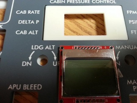
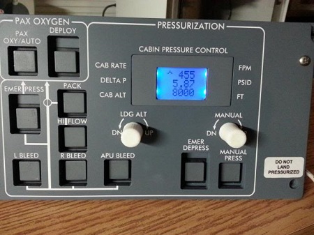
![]()
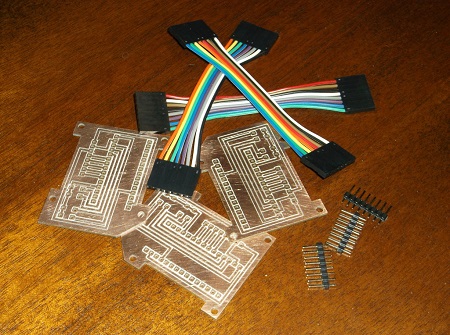
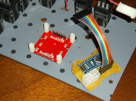
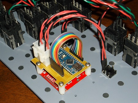
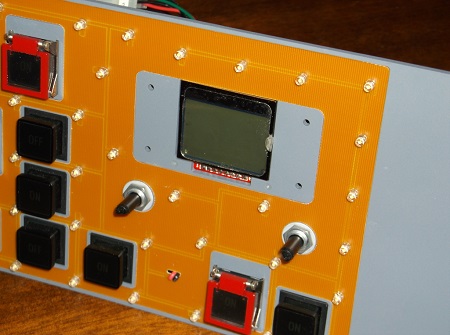
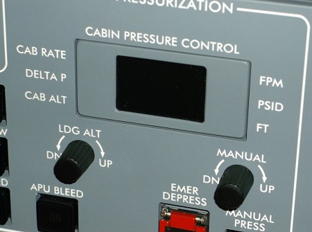
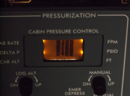
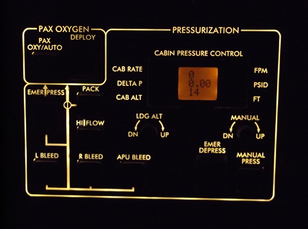
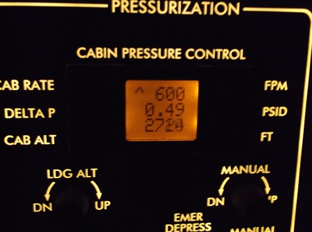
![]()
![]()
![]()
![]()
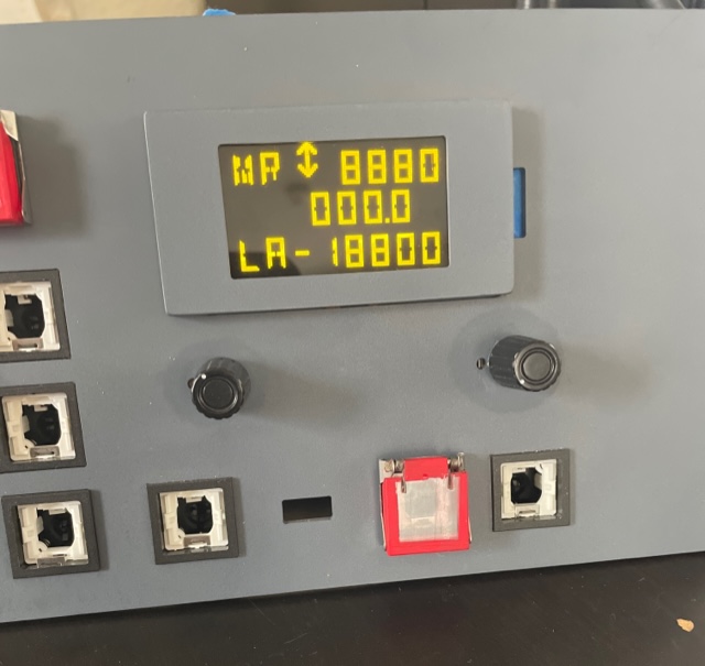
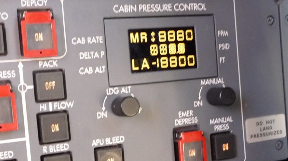
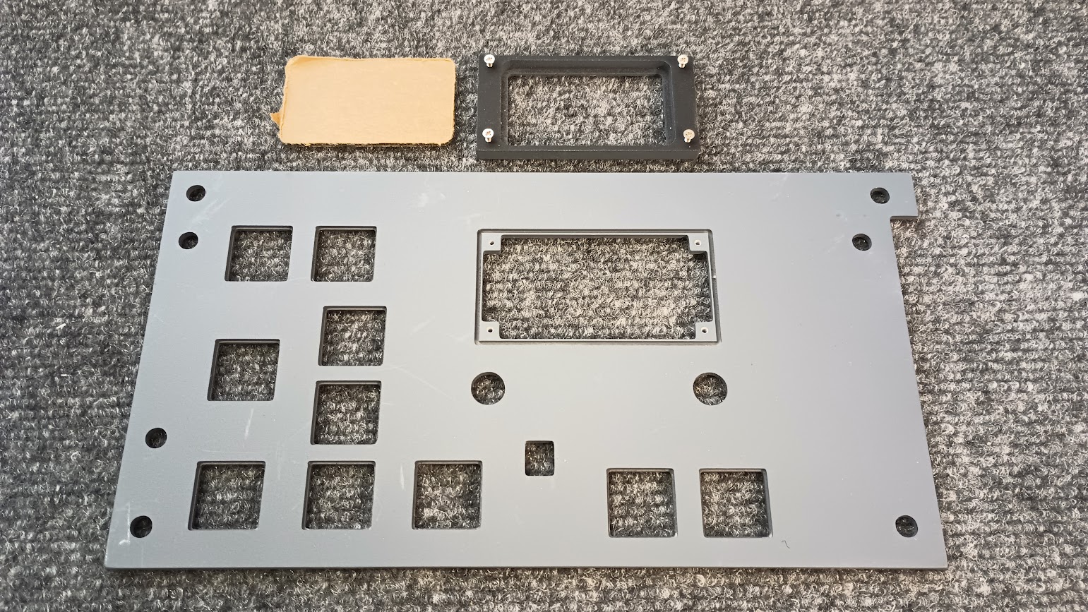
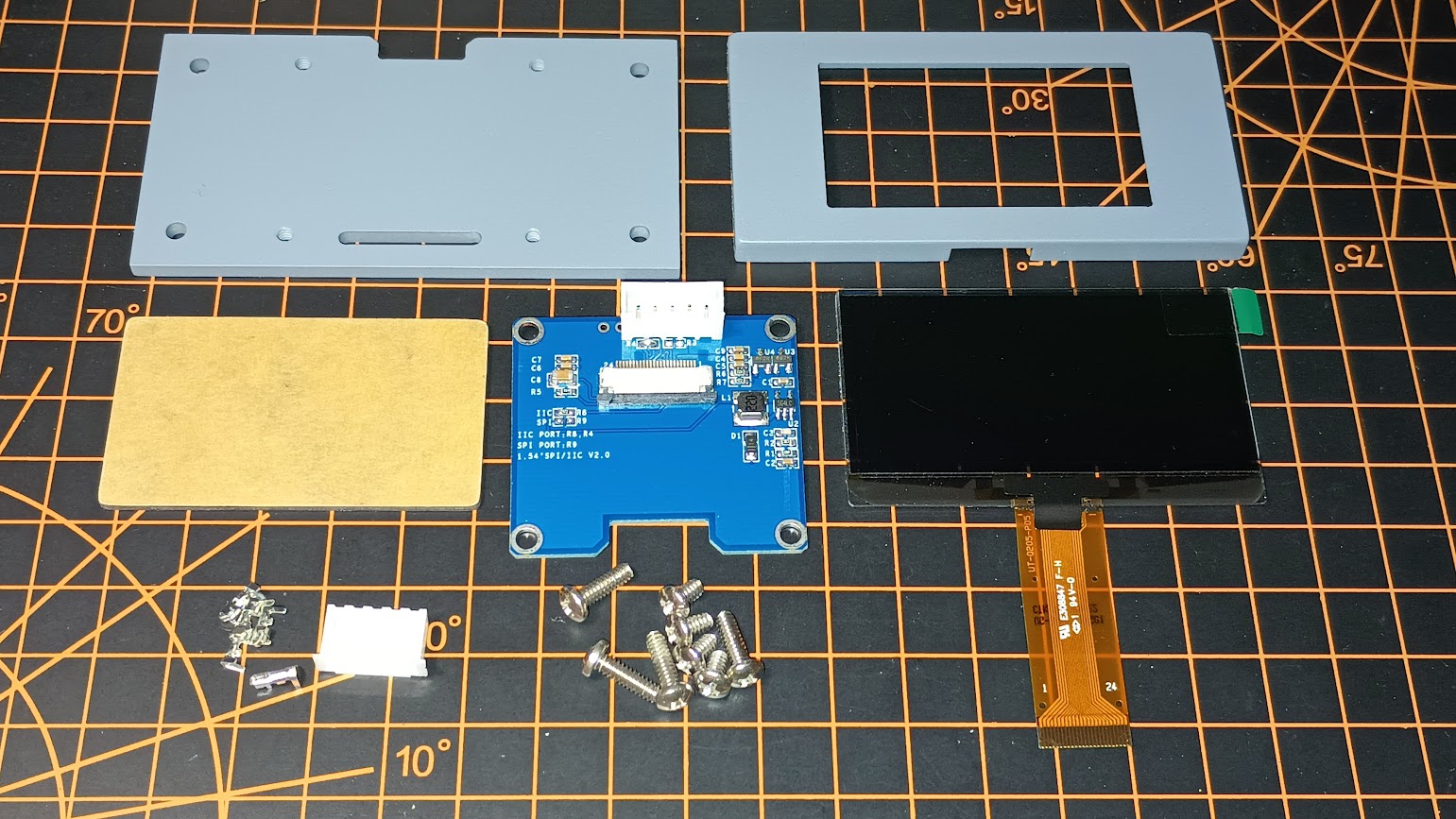
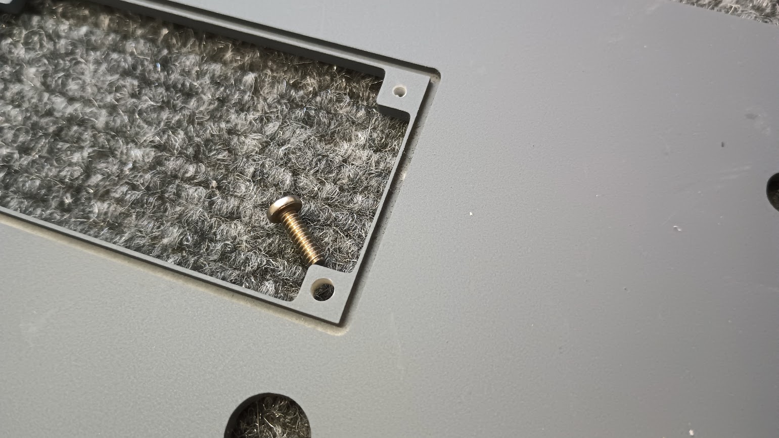
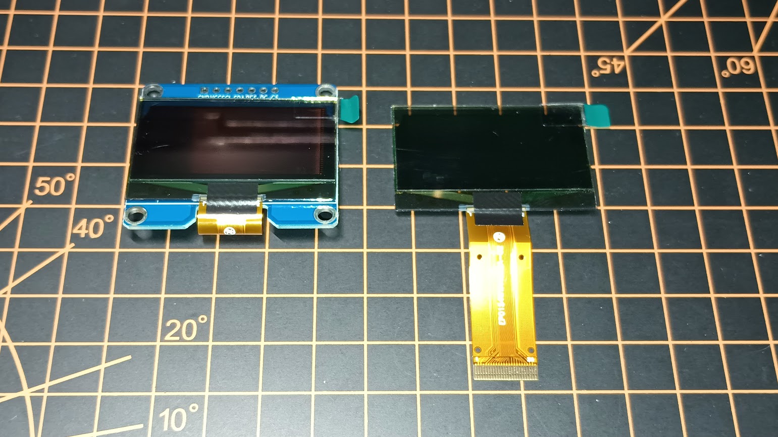
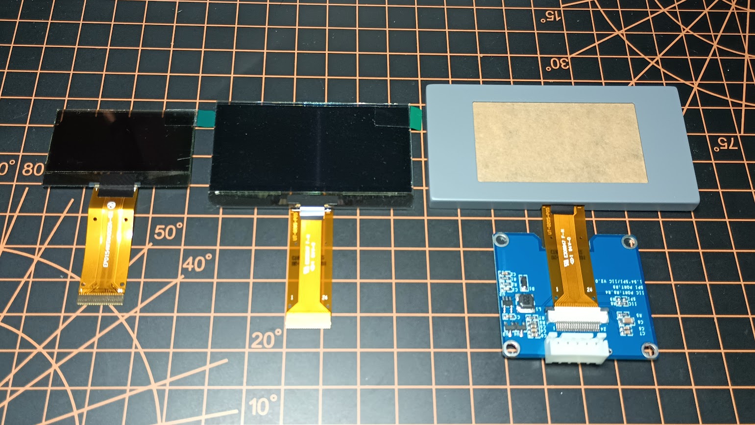
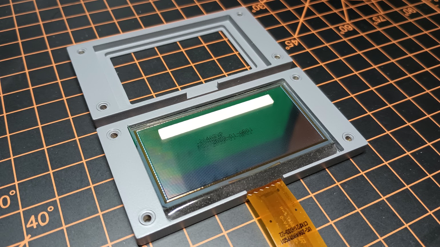
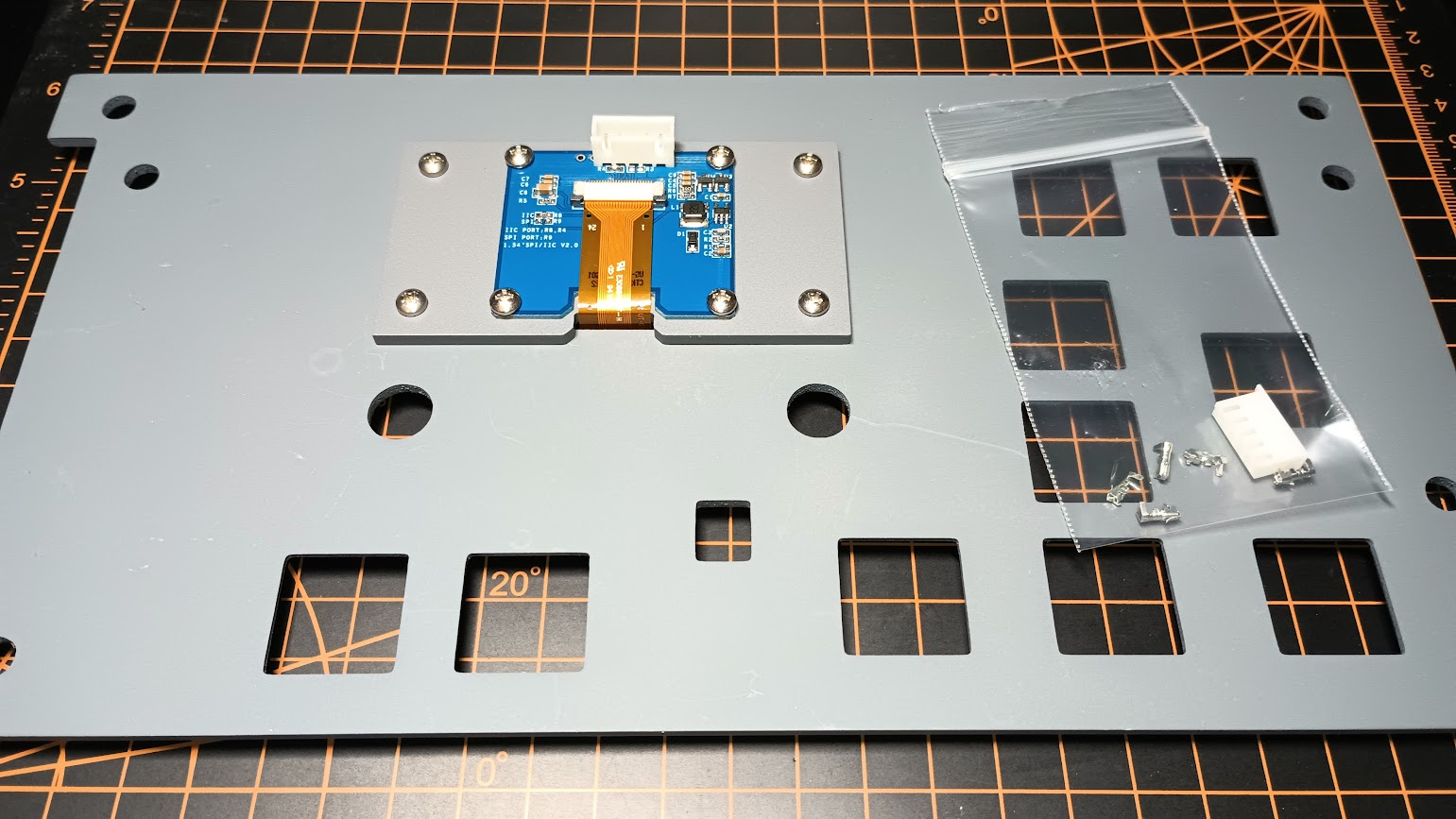
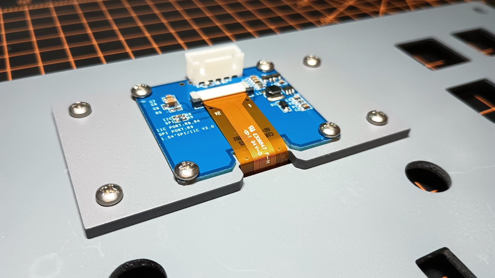
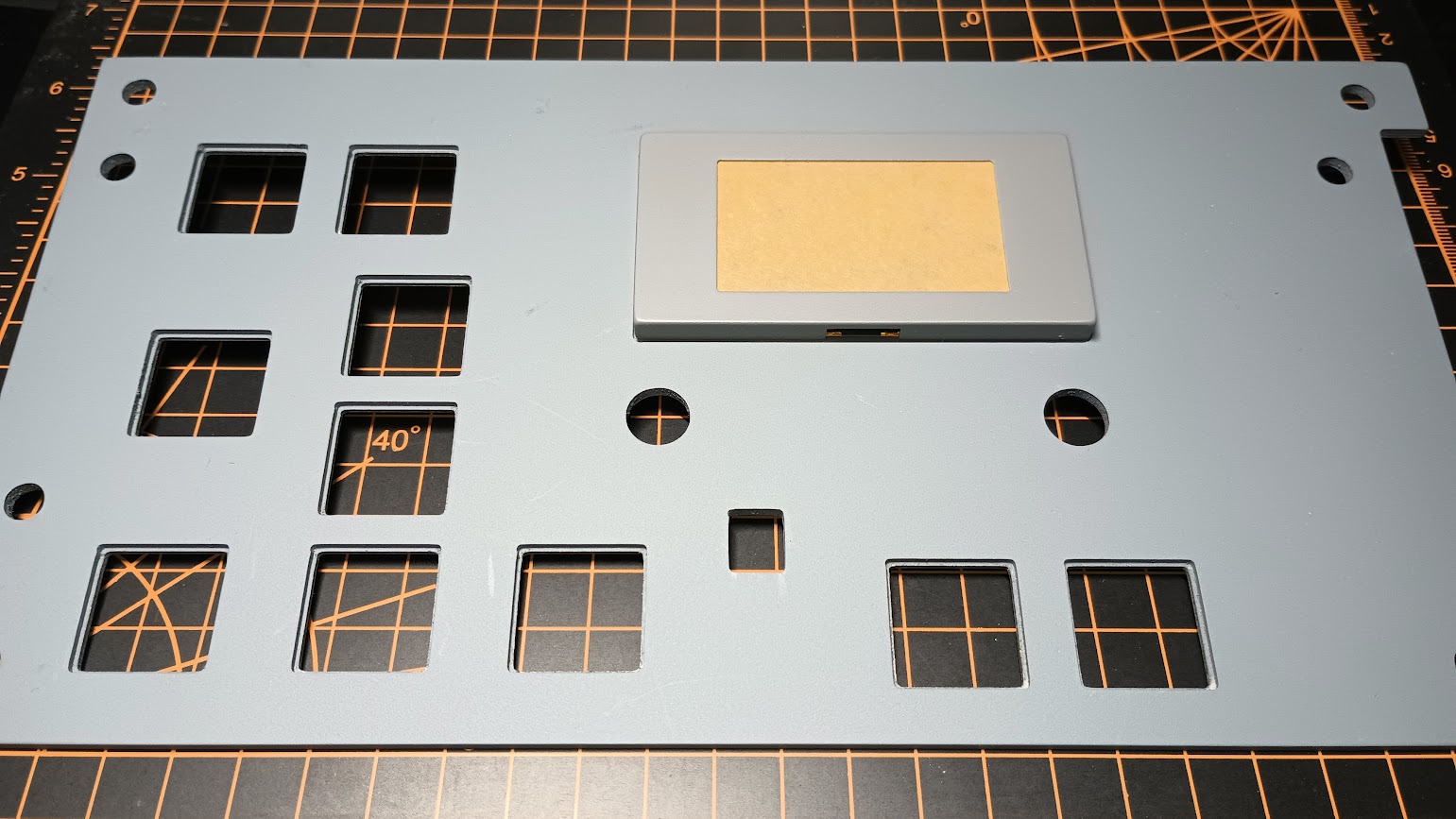
![]()
![]()
2017-10-10