


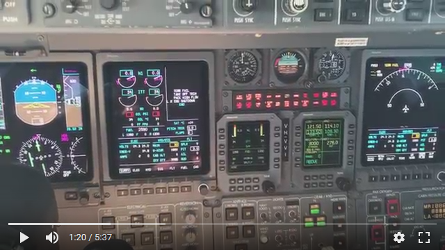
Ask a real world Learjet45XR pilot a question about the finer points of the Lear45 operation! Lear45XR Capt Dugald Boyd has kindly offered his assistance to us. I personally have dozens of questions but will limit myself to just one for now. If any of you have a Lear45 specific question in reference to a technical aspect, a physical aspect or an operational question, please post it here. My first question is in reference to the Master Caution Warning panels or Reversion panels. We are working on modeling the rotary selector switches on these two panels and would like a better understanding of what to expect when we turn the knob from OFF to DU 2 NORM or to PFD on the CAPT side and from OFF to DU 3 NORM on the FO side. My second part of this question is, from a pilot's perspective, what is the purpose of turning off the other displays with the exception of the EICAS? We have seen this in a few photos and videos. Thanks Dugald for your assistance! Ask a real world Learjet45XR pilot a question about the finer points of the Lear45 operation! Lear45XR Capt Dugald Boyd has kindly offered his assistance to us. I personally have dozens of questions but will limit myself to just one for now. If any of you have a Lear45 specific question in reference to a technical aspect, a physical aspect or an operational question, please post it here. My first question is in reference to the Master Caution Warning panels or Reversion panels. We are working on modeling the rotary selector switches on these two panels and would like a better understanding of what to expect when we turn the knob from OFF to DU 2 NORM or to PFD on the CAPT side and from OFF to DU 3 NORM on the FO side. My second part of this question is, from a pilot's perspective, what is the purpose of turning off the other displays with the exception of the EICAS? We have seen this in a few photos and videos. Thanks Dugald for your assistance! Ron, Thank you for your question regarding the PDF reversion panel. One of the key reasons for selecting the primary flight display: PFD 1 , PFD 3 or PFD 4 to the off position or to the PFD positions really for electrical load shedding in event of a dual generator failure. Sometimes the primary flight display's dimmer/brightness controller is used to darken / blacken screen during training to simulate a display failure to test limited panel flying skills. Another reason that I have experienced, that warranted the selection from "NORM" to "PFD" or ("OFF" captain's side only) was when I had a PFD #1 Amber overheat CAS message displayed. Those old CRT (TV screens) create an enormous amount of heat. The "wee-mac" air vent ducting on the captain's side runs very close to the PFD which could be a factor in an overheat situation. Mate in short the only time you would opt to turn off 3 PFD's and keep PFD 2 EICAS on is basically during an electrical system failure namely a dual GEN. Failure. The PFD 's chew a great deal of power and load shedding must be done to protect the Emer. Battery. The EMER BATTERY will only provide approximately 55mins - 1 hour of electrical power to com.1 flaps, gear selection and RMU 'S you may need the power if you have to shoot an instrument approach if in IMC or at night. Once the failure has been taken care of the EICAS would be then transferred to the RMU 850 ENGINE page and subsequently the PFD then turned off. I hope this help answer your question and sorry in advance for any grammatical errors. If you need anything video demonstrations of the reversion panel in action I would be more than happy to help out. Kind regard, Dugald Boyd
Ron, Thank you for your question regarding the PDF reversion panel. One of the key reasons for selecting the primary flight display: PFD 1 , PFD 3 or PFD 4 to the off position or to the PFD positions really for electrical load shedding in event of a dual generator failure. Sometimes the primary flight display's dimmer/brightness controller is used to darken / blacken screen during training to simulate a display failure to test limited panel flying skills. Another reason that I have experienced, that warranted the selection from "NORM" to "PFD" or ("OFF" captain's side only) was when I had a PFD #1 Amber overheat CAS message displayed. Those old CRT (TV screens) create an enormous amount of heat. The "wee-mac" air vent ducting on the captain's side runs very close to the PFD which could be a factor in an overheat situation. Mate in short the only time you would opt to turn off 3 PFD's and keep PFD 2 EICAS on is basically during an electrical system failure namely a dual GEN. Failure. The PFD 's chew a great deal of power and load shedding must be done to protect the Emer. Battery. The EMER BATTERY will only provide approximately 55mins - 1 hour of electrical power to com.1 flaps, gear selection and RMU 'S you may need the power if you have to shoot an instrument approach if in IMC or at night. Once the failure has been taken care of the EICAS would be then transferred to the RMU 850 ENGINE page and subsequently the PFD then turned off. I hope this help answer your question and sorry in advance for any grammatical errors. If you need anything video demonstrations of the reversion panel in action I would be more than happy to help out. Kind regard, Dugald Boyd
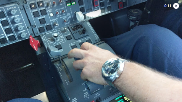
Thank you for the information Dugald! Very nice having a real world Lear pilot to be able to ask those operational questions. I noted in one of the photos you posted what appears to be USB charging ports below the Davtron clock. This is the first time I have seen this. Can you confirm those are charging ports? Ron and I were talking today and this would be a nice feature to add to the updates he is working on especially for those using iPad's in the flight deck. Once again, thank you for sharing your knowledge with us! It is very much appreciated! Shane Thank you for the information Dugald! Very nice having a real world Lear pilot to be able to ask those operational questions. I noted in one of the photos you posted what appears to be USB charging ports below the Davtron clock. This is the first time I have seen this. Can you confirm those are charging ports? Ron and I were talking today and this would be a nice feature to add to the updates he is working on especially for those using iPad's in the flight deck. Once again, thank you for sharing your knowledge with us! It is very much appreciated! Shane Thank you Dugald for the great explanation! We figured it had a lot to do with system redundancy in case of emergency situations. In any case, we are modeling this system which is cool just to know that it will be there and working! Eagle Eye Shane pointed out to me what appears to be powered USB plugs in one of the photos. What is the back story on those? We have never seen them before. This is a good example of an update we would like to include in our sims. Thanks for your help with bringing a greater understanding of the Lear45 to us all! Thank you Dugald for the great explanation! We figured it had a lot to do with system redundancy in case of emergency situations. In any case, we are modeling this system which is cool just to know that it will be there and working! Eagle Eye Shane pointed out to me what appears to be powered USB plugs in one of the photos. What is the back story on those? We have never seen them before. This is a good example of an update we would like to include in our sims. Thanks for your help with bringing a greater understanding of the Lear45 to us all! Ron, Shane, Firstly I am sorry for the delay in replying I've been a little bit busy flying around and haven't had an opportunity to reply. The USB charger ports (well spotted Shane) are an STC modification used to charge our IPAD mini's (Poor man's EFB) All our documents are stored on them for easy access in flight including our flight plans, and charts "Jeppview" "JEPP FD". I will send some more photos through for all to study. Regards Dugald Ron, Shane, Firstly I am sorry for the delay in replying I've been a little bit busy flying around and haven't had an opportunity to reply. The USB charger ports (well spotted Shane) are an STC modification used to charge our IPAD mini's (Poor man's EFB) All our documents are stored on them for easy access in flight including our flight plans, and charts "Jeppview" "JEPP FD". I will send some more photos through for all to study. Regards Dugald Very nice photo Dugald! I like the blue carpeting too, I don't know if I have ever seen that in the past. Myself and a few of the guys have a few questions for you: 1. Can you help shed some light on the FGC Vertical navigation, Vertical Speed, Speed selection and FLC? This is another area that we are in the middle of modeling in software and although we have a pretty good idea of how it works and what to expect, it would be cool to here from you what some of the practical aspects of these flight guidance tools do for "the pilots". 2. The other little thing that we were curious about is the secondary pitch trim switch. It is a split switch but so far, we can not find any documentation referring to when it is used interdependently from each side. This is a snip from the L45 Operations Reference Manual: "The dual-segment SEC trim switch (Fig 44) is located on the center pedestal. Manual activation of secondary trim requires that the pitch trim selector be in the SEC position and that both segments of the spring-loaded SEC switch be moved at the same time." Thanks Dugald for sharing your expertise with us! Very nice photo Dugald! I like the blue carpeting too, I don't know if I have ever seen that in the past. Myself and a few of the guys have a few questions for you: 1. Can you help shed some light on the FGC Vertical navigation, Vertical Speed, Speed selection and FLC? This is another area that we are in the middle of modeling in software and although we have a pretty good idea of how it works and what to expect, it would be cool to here from you what some of the practical aspects of these flight guidance tools do for "the pilots". 2. The other little thing that we were curious about is the secondary pitch trim switch. It is a split switch but so far, we can not find any documentation referring to when it is used interdependently from each side. This is a snip from the L45 Operations Reference Manual: "The dual-segment SEC trim switch (Fig 44) is located on the center pedestal. Manual activation of secondary trim requires that the pitch trim selector be in the SEC position and that both segments of the spring-loaded SEC switch be moved at the same time." Thanks Dugald for sharing your expertise with us! Ron, Thank you for your questions. Firstly referencing the V/S mode on the FGC is usually used during a descent specifically when transferring from FMS source / NAV mode on FGC. to NAV source/NAV mode FGC. during the intercept of an ILS . When transitioning between modes I.e. from FMS - NAV the VNAV will drop out and "PIT" mode will be displayed and an associated amber "MSG" will flash on the FMS indicating that "VNAV DISCONNECTED" . 2.)The secondary pitch trim is used for both "Mach trim" protection through the autopilot and for redundancy should the primary pitch trim fail. One only needs to recall the "2000 crash of Alaska Airlines Flight 261, which was caused by a broken jackscrew." The Lear 45 has 2 actuators in the tail. If you study a photo of the vertical fin some inspection panels can bee seen. Behind the screwed panels are where the actuators are located. Now with regards to the secondary pitch trim split switch, this is a safety feature similar to the rudder trim to prevent unintentional operation. Both halves / sides of the switch must be depressed and held to operate the trim I.e. nose down or nose up. Releasing the switch halves will spring load them back to the off/center position. It is very important to ensure that the trim switch is selected to primary "PRI" before takeoff and after testing it's function during the preflight. Ron, Thank you for your questions. Firstly referencing the V/S mode on the FGC is usually used during a descent specifically when transferring from FMS source / NAV mode on FGC. to NAV source/NAV mode FGC. during the intercept of an ILS . When transitioning between modes I.e. from FMS - NAV the VNAV will drop out and "PIT" mode will be displayed and an associated amber "MSG" will flash on the FMS indicating that "VNAV DISCONNECTED" . 2.)The secondary pitch trim is used for both "Mach trim" protection through the autopilot and for redundancy should the primary pitch trim fail. One only needs to recall the "2000 crash of Alaska Airlines Flight 261, which was caused by a broken jackscrew." The Lear 45 has 2 actuators in the tail. If you study a photo of the vertical fin some inspection panels can bee seen. Behind the screwed panels are where the actuators are located. Now with regards to the secondary pitch trim split switch, this is a safety feature similar to the rudder trim to prevent unintentional operation. Both halves / sides of the switch must be depressed and held to operate the trim I.e. nose down or nose up. Releasing the switch halves will spring load them back to the off/center position. It is very important to ensure that the trim switch is selected to primary "PRI" before takeoff and after testing it's function during the preflight. Thanks Dugald! Here is another easy question for you: When operating the reversers, when you pull the reverser levers back to the first detent, how many seconds pass before the balk solenoids release making it possible to pull the reverser levers back all the way to actually deploy the reverser clam doors on the engines? My guess is two or three seconds, but I figured I would ask you, the guy who has done it thousands of times. A few of us are also in the process of updating our TQs to include the ability to lock out the reverser levers. I will add a photo or two later of the inside mechanical workings. Thanks Dugald! Here is another easy question for you: When operating the reversers, when you pull the reverser levers back to the first detent, how many seconds pass before the balk solenoids release making it possible to pull the reverser levers back all the way to actually deploy the reverser clam doors on the engines? My guess is two or three seconds, but I figured I would ask you, the guy who has done it thousands of times. A few of us are also in the process of updating our TQs to include the ability to lock out the reverser levers. I will add a photo or two later of the inside mechanical workings. Hey guys, this post is courtesy of Dugald who was having internet issues down under. He was able to send me a link via email of a video he took of the reverser balk solenoids in action. The video answers the question: Q: How long is the delay once the pilots select the reverser levers and pull them back to the first detent? A: The answer is just less than one second. I actually used a stop watch and timed it a few times and got between .75 and .85 seconds. For us Lear45 sim guys, .80 seconds represents the micro switches being activated, the software sending a signal to the relays and the relays sending power to the balk solenoids. Watch this short video. Maximize the screen so you can hear the solenoids activating! Thanks to Dugald for taking the time to make this short video and answering this question completely! Hey guys, this post is courtesy of Dugald who was having internet issues down under. He was able to send me a link via email of a video he took of the reverser balk solenoids in action. The video answers the question: Q: How long is the delay once the pilots select the reverser levers and pull them back to the first detent? A: The answer is just less than one second. I actually used a stop watch and timed it a few times and got between .75 and .85 seconds. For us Lear45 sim guys, .80 seconds represents the micro switches being activated, the software sending a signal to the relays and the relays sending power to the balk solenoids. Watch this short video. Maximize the screen so you can hear the solenoids activating! Thanks to Dugald for taking the time to make this short video and answering this question completely! Hey guys! Courtesy of Dugald, he made us a short video of some of the initial electrical switch selection functions and the System light test feature. Additionally, take note of the aural warning sounds and which ones can be muted and which ones can not. By the way, this is the question that prompted this video: Do the green indicator lights on the FGC buttons illuminate during the System Light Test? Click on the image below to find out if they do! Thank you Dugald for your continued insider support in helping us all understand the finer points of the Lear45! Hey guys! Courtesy of Dugald, he made us a short video of some of the initial electrical switch selection functions and the System light test feature. Additionally, take note of the aural warning sounds and which ones can be muted and which ones can not. By the way, this is the question that prompted this video: Do the green indicator lights on the FGC buttons illuminate during the System Light Test? Click on the image below to find out if they do! Thank you Dugald for your continued insider support in helping us all understand the finer points of the Lear45!A Lear45XR Expert Point of View
![]()
![]()
![]()
![]()
![]()
![]()
![]()
![]()
![]()
![]()
Forum NavigationA Lear45XR Expert Point of View
![]() #1 · May 30, 2018, 11:21 am
#1 · May 30, 2018, 11:21 am![]() #2 · May 30, 2018, 7:34 pmX
#2 · May 30, 2018, 7:34 pmX![]() #3 · May 30, 2018, 9:03 pm
#3 · May 30, 2018, 9:03 pm![]() #4 · May 30, 2018, 10:18 pm
#4 · May 30, 2018, 10:18 pm![]() #5 · June 9, 2018, 1:18 amX
#5 · June 9, 2018, 1:18 amX![]() #6 · June 10, 2018, 6:52 pm
#6 · June 10, 2018, 6:52 pm![]() #7 · June 14, 2018, 5:11 amX
#7 · June 14, 2018, 5:11 amX![]() #8 · June 15, 2018, 11:56 am
#8 · June 15, 2018, 11:56 am![]() #9 · June 19, 2018, 8:22 am
#9 · June 19, 2018, 8:22 am![]() #10 · November 26, 2018, 8:37 pm
#10 · November 26, 2018, 8:37 pm
2017-10-10